Table of Contents
Advertisement
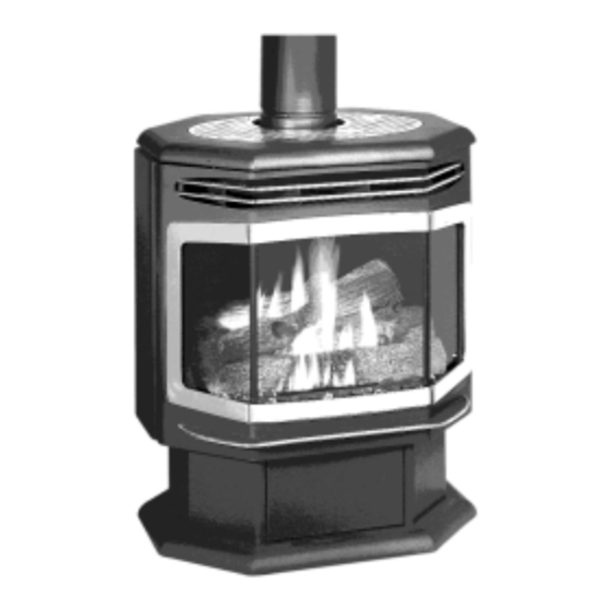
Featuring the
WARNING:
If the information in these instructions is not followed exactly, a fire or explosion
may result causing property damage, personal injury or loss of life.
-
Do not store or use gasoline or other flammable vapors and liquids in the vicinity of this or
any other appliance.
WHAT TO DO IF YOU SMELL GAS
• Do not try to light any appliance.
• Do not touch any electrical switch; do not use any phone in your building.
• Immediately call gas supplier from a neighbor's phone. Follow the gas supplier's instructions.
• If you cannot reach your gas supplier, call the fire department.
-
Installation and service must be performed by a qualified installer, service agency or the gas
supplier.
This appliance may be installed as an OEM installation in a manufactured (mobile) home and
must be installed in accordance with the manufacturer's instructions and the manufactured
home construction and safety standard, Title 24 CFR, Part 3280 or Standard for Installation in
Mobile Homes, CAN/CSA Z240 MH.
This appliance is only for use with the type(s) of gas indicated on the rating plate. A conversion
kit is supplied with the appliance.
Installer: After installation give this manual to the home-
owner and explain operation of this stove.
Copyright 2000, T.I.
$10.00
Salish Owner's Manual
Part # 93508122
• Direct Vent Freestanding Stove
• Natural Gas or Propane
• Vent Horizontally or Vertically
• Standard Residential
• Mobile Home Approved
Burner
ANSI Z21.88, CSA 2.33 M9 8, CAN/CGA 2.17-M91
Tested and Listed by
Omni-Test Laboratories, Inc.
Beaverton, Oregon
Report # 028–S–14-1
10850 117th Place N.E. Kirkland, WA 98033
Advertisement
Table of Contents

Related Manuals for Travis Industries Avalon


Summary of Contents for Travis Industries Avalon
- Page 1 • Direct Vent Freestanding Stove • Natural Gas or Propane • Vent Horizontally or Vertically • Standard Residential • Mobile Home Approved Tested and Listed by Omni-Test Laboratories, Inc. Beaverton, Oregon Report # 028–S–14-1 Featuring the Burner ANSI Z21.88, CSA 2.33 M9 8, CAN/CGA 2.17-M91 WARNING: If the information in these instructions is not followed exactly, a fire or explosion may result causing property damage, personal injury or loss of life.
-
Page 3: Introduction
Bill of Sale to this page so that you will have all the information you need in one place should the need for service or information occur. Travis Industries 9 3 5 0 8 1 2 2 1 4 1 1 0 0... -
Page 4: Safety Precautions
• Keep all furniture or other combustible items at least 36” away from the front of the heater. Travis Industries 9 3 5 0 8 1 2 2 1 4 1 1 0 0... -
Page 5: Safety Precautions
Always follow the instructions in this manual. • If the fiber logs become damaged, replace with Travis Industries log set. • Do not touch the hot • Plug the heater into a 120V surfaces of the heater. -
Page 6: Table Of Contents
Termination Requirements ........13 Interior Masonry Chimney Conversions ....37 Finalizing the Installation ........14 Index Opening the Door ..........16 Log Set and Coal Installation ........17 Index...............38 Travis Industries 9 3 5 0 8 1 2 2 1 4 1 1 0 0... -
Page 7: Specifications
28" 21-1/2" Electrical Specifications Electrical Rating............115 Volts, 0.8 Amps, 60 Hz (92 watts on high) Travis Industries 9 3 5 0 8 1 2 2 1 4 1 1 0 0... -
Page 8: Installation
When the stove is installed in a mobile home, it must be bolted to the floor and the appliance grounded (use the blower with a grounded circuit or other suitable grounding method - current ANSI/NFPA 70 or CSA C22.1). Travis Industries 9 3 5 0 8 1 2 2 1 4 1 1 0 0... -
Page 9: Heater Placement Requirements
Standard Input Pressure Natural Gas 7” W.C. (1.74 Kpa) Pr o p an e 13” W.C. (3.23 Kpa) Travis Industries 9 3 5 0 8 1 2 2 1 4 1 1 0 0... -
Page 10: Vent Requirements
Horizontal sections require a 1/4” rise every 12” of travel Exterior Vent Diameter = 6-5/8” , Inner Vent Diameter = 4” • Horizontal sections require non-combustible support every 36” (e.g.: use plumbing tape) Travis Industries 9 3 5 0 8 1 2 2 1 4 1 1 0 0... -
Page 11: Approved Vent Configurations
1-1/2" (37 mm) The starter section is 1/4"" above Vent Length 1-1/2" the top (3', 4', etc.) (37 mm) (910, 1210 mm) Travis Industries 9 3 5 0 8 1 2 2 1 4 1 1 0 0... -
Page 12: Vertical Term's With (Or Without) 2 45° Elbows
5 feet 5 feet NOTE: four 4' sections. The maximum offset lengths, combined, is four 4' sections. 0 feet 0 feet 0 feet 0 feet Travis Industries 9 3 5 0 8 1 2 2 1 4 1 1 0 0... -
Page 13: Horizontal Terminations
(all shaded areas) 5 feet 5 feet NOTE: A minimum 3 foot rise is required directly off of the stove. 0 feet 0 feet Travis Industries 9 3 5 0 8 1 2 2 1 4 1 1 0 0... -
Page 14: Vertical Term's With Two 90° Elbows
(H1 + H2 = horizontal vent length). This is considered a vertical elbow Travis Industries 9 3 5 0 8 1 2 2 1 4 1 1 0 0... -
Page 15: Termination Requirements
Vent termination must not be located where it will become plugged by snow or other material • These clearances meet UMC-1994 and the CNA/CGA-B149 code standards. Travis Industries 9 3 5 0 8 1 2 2 1 4 1 1 0 0... -
Page 16: Finalizing The Installation
Flames should be blue at the on the ends, push the air control in. short, pull the air control out. base, yellow-orange on the top. Travis Industries 9 3 5 0 8 1 2 2 1 4 1 1 0 0... - Page 17 Give this manual to the home owner and fully explain the operation of this heater. Travis Industries 9 3 5 0 8 1 2 2 1 4 1 1 0 0...
-
Page 18: Opening The Door
NOTE: Do not overtighten the pawl by screwing it in. This will permanently damage the latch. Travis Industries 9 3 5 0 8 1 2 2 1 4 1 1 0 0... -
Page 19: Log Set And Coal Installation
Place the front left log stand over this pin. Travis Industries 9 3 5 0 8 1 2 2 1 4 1 1 0 0... - Page 20 Note how the front left log is Do not place logs over spaced 1/4” to 3/8” off of the burner holes. burner holes. Travis Industries 9 3 5 0 8 1 2 2 1 4 1 1 0 0...
- Page 21 Step 4 Install the embers along the front of the burner (see the illustrations below). Do not place the embers over the burner holes. Front View Side View Travis Industries 9 3 5 0 8 1 2 2 1 4 1 1 0 0...
-
Page 22: Operation
If using a remote control or thermostat, the On/Off Switch must be left “ON”. Turning the On/Off Switch “OFF” will keep the heater off always. Travis Industries 9 3 5 0 8 1 2 2 1 4 1 1 0 0... -
Page 23: Starting The Pilot Flame
Close and latch the door. Turn the gas control knob counter-clockwise to "ON". The pilot is now lit and the heater can be turned on and off. Travis Industries 9 3 5 0 8 1 2 2 1 4 1 1 0 0... -
Page 24: Starting The Heater For The First Time
Index Mark Flame Height Adjustment Knob Turn counter-clockwise to adjust the flame higher, clockwise to lower. Travis Industries 9 3 5 0 8 1 2 2 1 4 1 1 0 0... -
Page 25: Adjusting The Blower Speed
As the gas control valve is turned on and off you will hear a dull clicking sound. This is the valve opening up and shutting down. Travis Industries 9 3 5 0 8 1 2 2 1 4 1 1 0 0... -
Page 26: Maintenance
Remove any debris or vegetation near the vent termination. Contact your dealer if any sooting or deterioration is found near the vent termination. Travis Industries 9 3 5 0 8 1 2 2 1 4 1 1 0 0... -
Page 27: Troubleshooting Steps
Flames Are Too Short The flame height may be turned too low....Turn the flame height to “HI” - See “Adjusting the Flame Height” (Under 6”) Travis Industries 9 3 5 0 8 1 2 2 1 4 1 1 0 0... -
Page 28: How This Heater Works
If the pilot flame tested to be extremely resistant to goes out, the gas valve automatically breakage from temperature changes. shuts off all gas. Travis Industries 9 3 5 0 8 1 2 2 1 4 1 1 0 0... -
Page 29: Wiring Diagram
Log, Rear 93006518 Thermocouple, S.I.T. 93006804 Log, Right 93006920 Threaded Pipe Adapter - 5/8 x 1/2 93006800 Log Set 93006505 Wiring Harness 98900747 On/Off Switch Travis Industries 9 3 5 0 8 1 2 2 1 4 1 1 0 0... -
Page 30: Safety Label
Manufacture 2000 Jan. Apr. Jul. Oct. Date: 2001 Feb. Aug. Nov. 10850 117th Pl. N.E. Kirkland, WA 98033 2002 Mar. Jun. Sep. Dec. 0332 Travis Industries 9 3 5 0 8 1 2 2 1 4 1 1 0 0... -
Page 31: Warranty
TRAVIS INDUSTRIES, INC. TRAVIS INDUSTRIES, INC., at its option, will repair or replace, free of charge, your TRAVIS appliance if it is found to be defective in material or workmanship within the time frame stated within this 7 year warranty. TRAVIS INDUSTRIES, INC. will return your appliance, freight charges (years 1 to 5) prepaid by TRAVIS INDUSTRIES, INC., to your regional distributor, or dealership. -
Page 32: Optional Equipment & Addenda
NOTE: After replacing the burner, make sure this “O” ring Burner Tube seals the burner tube to the mixing tube. Mixing Tube Travis Industries 9 3 5 0 8 1 2 2 1 4 1 1 0 0... - Page 33 (indicating full insertion). correct orifices. Front Burner 1/2" Wrench Orifice 5/16” 5/16” Look here for the orifice identification Rear Burner Orifice Front Rear Travis Industries 9 3 5 0 8 1 2 2 1 4 1 1 0 0...
- Page 34 (or T-20 Torx) regulator gasket is correctly burner is lit. aligned before installation. Place the LP label on the plate near the gas control valve. Travis Industries 9 3 5 0 8 1 2 2 1 4 1 1 0 0...
-
Page 35: Fireback
“a”. Secure the with the fireback clips and the fireback with the screw removed in screws removed in step “b”. step “b”. Travis Industries 9 3 5 0 8 1 2 2 1 4 1 1 0 0... -
Page 36: Wall Thermostat
“a”. Standard Screwdriver Set the on/off switch on the stove to “Off”. If turned to “On” the stove will remain on always. Travis Industries 9 3 5 0 8 1 2 2 1 4 1 1 0 0... -
Page 37: Remote Thermostat
Use denatured alcohol and a soft cloth to clean. Denatured Alcohol Soft Cloth Travis Industries 9 3 5 0 8 1 2 2 1 4 1 1 0 0... -
Page 38: Gold Trivet
Any marks left on the gold Denatured may become etched-in by the heat of Alcohol the stove. Use denatured alcohol and Soft Cloth a soft cloth to clean. Travis Industries 9 3 5 0 8 1 2 2 1 4 1 1 0 0... -
Page 39: Installation Addenda
1” clearance to any Connector (included in #934 combustible. The vent must be Masonry Conversion Kit) sealed air-tight. secured and sealed to block-off plate. Travis Industries 9 3 5 0 8 1 2 2 1 4 1 1 0 0... -
Page 40: Index
Horizontal Vent Termination Requirements ..13 Wiring Diagram..........27 How to Measure Vent Lengths ....9 Yearly Service Procedure......24 Installation Options ........5 Installation Preparation........6 Leaking Gas .......See Inst. on Cover Travis Industries 9 3 5 0 8 1 2 2 1 4 1 1 0 0...