Table of Contents
Advertisement
Advertisement
Table of Contents

Related Manuals for Solahart SOLAR WATER HEATERS


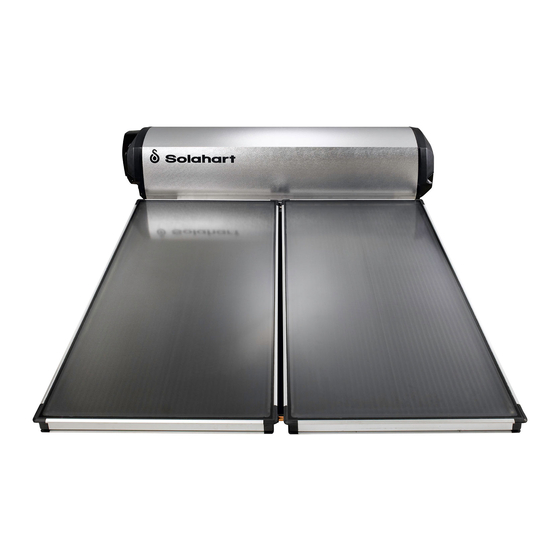
Summary of Contents for Solahart SOLAR WATER HEATERS
- Page 1 OWNER’S MANUAL SOLAR WATER HEATERS Solahart Industries Pty Ltd ABN 45 064 945 848...
-
Page 2: Table Of Contents
CONTENTS Solahart Technology Here's How It Works Operating Hints Facts You Should Know About Your Water Heater Maintenance Installation Instructions - All Models Installation Instructions – Closed Circuit Series Heat Dissipation Kit (Assembly and Installation) Installation Instructions - L Series... -
Page 3: Solahart Technology
33-1197 Solahart Owner’s Manual – Thermosyphon Systems - Revision A – September 2003 WORLD'S LEADING TECHNOLOGY Your Solahart is equipped with the latest technology in solar water heaters. The Closed Circuit Series feature collectors that contain a special heat transfer fluid called ‘Hartgard’ which acts to enhance the performance of your Solahart water heater. -
Page 4: Here's How It Works
Series uses a direct heating method that relies upon the same Thermosyphon Principle, but circulates potable water through the collectors. The Solahart collectors absorb solar energy. The tempered, low-iron, solar glass allows more radiation to pass through and be retained than other traditional float glass systems. -
Page 5: Operating Hints
With a two panel, 300 litre Solahart hot water heater, on a clear winter day, the collectors can raise the tank temperature to approximately twice the daily maximum temperature. For example on a clear 15ºC day the tank temperature can reach approximately 30ºC. -
Page 6: Facts You Should Know About Your Water Heater
Hot Hot Water! Your Solahart water heater will generate hot water quickly and efficiently. Under normal family use, it will operate between 60ºC and 70ºC. However, the temperature can exceed this and under certain circumstances may be as high as 95ºC. This can occur during prolonged periods of direct sunlight and particularly in summer or long periods of reduced water usage. -
Page 7: Maintenance
Booster fuse is sound. Electric or gas meter speeds up when the booster switch is turned ON after being OFF. Contact your local Solahart dealer if all of the above have been checked and there is still no hot water. Six Monthly Service Some water supply authorities generally require both the hot and cold water relief valves to be flushed every six months. - Page 8 Water Quality - Is it Suitable for the Solahart Water Heater? Your Solahart heater is suitable for use with water with a total dissolved solid content is less than 1,000 ppm and for which the total hardness does not exceed 200 ppm CaCO 3 . Water supplies having calcium hardness (CaCO 3 ), and an alkalinity in excess of 150 ppm should be treated by a softening process prior to use with this heater to prevent scaling and damage to the electric booster element.
- Page 9 Comparative Energy Savings - (Solahart 302L v 302J v 302KF) The figure below shows electric energy usage of Solahart solar hot water systems, compared to a 130 litre electric hot water system. The table is compiled for a daily usage rate of 160 litres of water for an average household in Perth, Western Australia.
-
Page 10: Installation Instructions - All Models
Local codes in Australia require all electrical work to be performed by a qualified electrician. ALL INSTALLATIONS ARE TO BE IN ACCORDANCE WITH LOCAL ELECTRICAL CODES APPLICABLE IN YOUR AREA. The power rating and current requirement of your Solahart heater will be specified on the heater’s data plate, located on the cover to the electrical cavity. - Page 11 STOVE COIL BOOSTERS Manually fed boosters such as stove coils, back boilers or coils in open fired grates are not permitted to be connected to Solahart heaters unless the storage cylinder is open vented. Such auxiliary energy sources must not be connected into the closed circuit. Installation details for these devices are available from Solahart on application.
-
Page 12: Installation Instructions - Closed Circuit Series
Operate both pressure relief valves easing gear to ensure that the valves are functional. The storage tank is now filled and ready to operate as an electric or gas water heater. To operate as a solar water heater, the closed circuit must be commissioned by an authorised Solahart... - Page 13 PR6 valve in its place ensuring the O’ ring is in place. Finally remove all packaging and unused items and ensure the roof is clean and tidy. The Solahart brand name sticker is fitted to the tank in the factory, however the sticker for the "Natural Wonder" (Gas Boosted) heaters must be fitted on site.
-
Page 14: Heat Dissipation Kit (Assembly And Installation)
33-1197 - Solahart Owner’s Manual – Thermosyphon Systems – Revision A – September 2003 INSTALLATION INSTRUCTIONS - HEAT DISSIPATION KIT All installations of ‘KF’ system collectors must also be fitted with a Heat Dissipation Kit. This kit should be fitted before the potable water tank is filled. -
Page 15: Connection Of Temperature Limiting Device
33-1197 Solahart Owner’s Manual – Thermosyphon Systems - Revision A – September 2003 INSTALLATION INSTRUCTIONS – ‘L’ SERIES (cont) Join the collectors using the collector unions provided (Part No. 33-0695). Apply only medium pressure with a spanner to tighten. Centralise the collectors on the rail. Lock the collectors to the rail with the 4 collector clamps. Tighten using the nuts and bolts provided. Fit the copper blanking discs (Part No. -
Page 16: Technical Data
33-1197 - Solahart Owner’s Manual – Thermosyphon Systems – Revision A – September 2003 TECHNICAL SPECIFICATIONS 181KF 181J 182KF FREE Systems 151L 151J 151KF 181L 181J 181KF 181KF BCXII 182L 182J 182KF FREE HEAT FREE HEAT HEAT Delivery litres (solar) US gal. - Page 17 33-1197 Solahart Owner’s Manual – Thermosyphon Systems - Revision A – September 2003 TECHNICAL SPECIFICATIONS (cont) 443KF 443J 444KF 444J Systems 443J 443KF 443KF BCXII 443JXII 444L 444J 444KF 444KF BCXII 444JXII FREE HEAT FREE HEAT FREE HEAT FREE HEAT...
-
Page 18: Installation Diagram - Model 151 Closed Circuit
33-1197 - Solahart Owner’s Manual – Thermosyphon Systems – Revision A – September 2003 INSTALLATION DIAGRAM - MODEL 151J & 151KF Please refer to the installation instructions for Closed Circuit models on Page 10 for information on pipe and valve frost damage, instructions on filling and commissioning the storage tank and closed circuit. -
Page 19: Installation Diagram - Model 151L
PLEASE NOTE Solahart Model 151L is not intended under any circumstances for use in a known frost area. A 151L system installed in a known frost area does not carry any warranty. Solahart Closed Circuit Series heaters are specially designed for frost prone and bad water areas and should always be installed in these conditions. -
Page 20: Installation Diagram - Model 181 Closed Circuit
33-1197 - Solahart Owner’s Manual – Thermosyphon Systems – Revision A – September 2003 INSTALLATION DIAGRAM - MODEL 181J, 181KF, 181KF FREE HEAT, 181J FREE HEAT & 181KF BCXII Please refer to the installation instructions for Closed Circuit models on Page 10 for information on pipe and valve frost damage, instructions on filling and commissioning the storage tank and closed circuit. -
Page 21: Installation Diagram - Model 181L
PLEASE NOTE Solahart Model 181L is not intended under any circumstances for use in a known frost area. A 181L system installed in a known frost area does not carry any warranty. Solahart Closed Circuit Series heaters are specially designed for frost prone and bad water areas and should always be installed in these conditions. -
Page 22: Installation Diagram - Model 182 Closed Circuit
33-1197 - Solahart Owner’s Manual – Thermosyphon Systems – Revision A – September 2003 INSTALLATION DIAGRAM - MODEL 182J, 182KF, 182KF FREE HEAT, 182J FREE HEAT & 182KF BCXII Please refer to the installation instructions for Closed Circuit models on Page 10 for information on pipe and valve frost damage, instructions on filling and commissioning the storage tank and closed circuit. -
Page 23: Installation Diagram - Model 221 Closed Circuit
33-1197 - Solahart Owner’s Manual – Thermosyphon Systems – Revision A – September 2003 INSTALLATION DIAGRAM - MODEL 221J, 221KF, 221KF BCXII & 221JXII Please refer to the installation instructions for Closed Circuit models on Page 10 for information on pipe and valve frost damage, instructions on filling and commissioning the storage tank and closed circuit. -
Page 24: Installation Diagram - Model 301 Closed Circuit
33-1197 - Solahart Owner’s Manual – Thermosyphon Systems – Revision A – September 2003 INSTALLATION DIAGRAM - MODEL 301J, 301KF, & 301KF BCXII Please refer to the installation instructions for Closed Circuit models on Page 10 for information on pipe and valve frost damage, instructions on filling and commissioning the storage tank and closed circuit. -
Page 25: Installation Diagram - Model 301L
PLEASE NOTE Solahart Model 301L is not intended under any circumstances for use in a known frost area. A 301L system installed in a known frost area does not carry any warranty. Solahart Closed Circuit Series heaters are specially designed for frost prone and bad water areas and should always be installed in these conditions. -
Page 26: Installation Diagram - Model 302 Closed Circuit
33-1197 - Solahart Owner’s Manual – Thermosyphon Systems – Revision A – September 2003 INSTALLATION DIAGRAM - MODELS 302J, 302KF, 302KF FREE HEAT, 302J FREE HEAT, 302KF BCXII & 302JXII Please refer to the installation instructions for Closed Circuit models on Page 10 for information on pipe and valve frost damage, instructions on filling and commissioning the storage tank and closed circuit. -
Page 27: Installation Diagram - Model 302L
PLEASE NOTE Solahart Model 302L is not intended under any circumstances for use in a known frost area. A 302L system installed in a known frost area does not carry any warranty. Solahart Closed Circuit Series heaters are specially designed for frost prone and bad water areas and should always be installed in these conditions. -
Page 28: Installation Diagram - Model 303 Closed Circuit
33-1197 - Solahart Owner’s Manual – Thermosyphon Systems – Revision A – September 2003 INSTALLATION DIAGRAM - MODELS 303J, 303KF, 303KF FREE HEAT, 303J FREE HEAT, 303KF BCXII & 303JXII Please refer to the installation instructions for Closed Circuit models on Page 10 for information on pipe and valve frost damage, instructions on filling and commissioning the storage tank and closed circuit. -
Page 29: Installation Diagram - Model 303L
PLEASE NOTE Solahart Model 303L is not intended under any circumstances for use in a known frost area. A 303L system installed in a known frost area does not carry any warranty. Solahart Closed Circuit Series heaters are specially designed for frost prone and bad water areas and should always be installed in these conditions. -
Page 30: Installation Diagram - Model 443 Closed Circuit
33-1197 - Solahart Owner’s Manual – Thermosyphon Systems – Revision A – September 2003 INSTALLATION DIAGRAM - MODELS 443J, 443KF, 443KF FREE HEAT, 443J FREE HEAT, 443KF BCXII & 443JXII Please refer to the installation instructions for Closed Circuit models on Page 10 for information on pipe and valve frost damage, instructions on filling and commissioning the storage tank and closed circuit. -
Page 31: Installation Diagram - Model 443L
PLEASE NOTE Solahart Model 443L is not intended under any circumstances for use in a known frost area. A 443L system installed in a known frost area does not carry any warranty. Solahart Closed Circuit Series heaters are specially designed for frost prone and bad water areas and should always be installed in these conditions. -
Page 32: Closed Circuit Series Water Connections
33-1197 - Solahart Owner’s Manual – Thermosyphon Systems – Revision A – September 2003 CLOSED CIRCUIT SYSTEMS WATER CONNECTIONS L SYSTEM WATER CONNECTIONS... -
Page 33: Combination Valve Assembly
33-1197 - Solahart Owner’s Manual – Thermosyphon Systems – Revision A – September 2003 COMBINATION VALVE ASSEMBLY ASSEMBLY DIAGRAMS DIAGRAM 1: COLLECTOR RAIL FIXING DIAGRAM 2: TANK FIXING DETAIL DIAGRAM 3: TANK CLAMP ASSEMBLY... - Page 34 33-1197 - Solahart Owner’s Manual – Thermosyphon Systems – Revision A – September 2003 ASSEMBLY DIAGRAMS DIAGRAM 4: WITH PITCH TILED ROOF MOUNTING Strap (330847) fixed with “TEK” self drilling screws (metal deck) or coach screws (fibro roof). 33-0847 331846...
-
Page 35: Warranty
CONDITIONS ALL MODELS The above is subject to an area within a 30 kilometre radius of the Solahart dealer from whom the unit was purchased. Customers outside this area will be subject to freight and travelling charges incurred by the Solahart dealer carrying out the work. - Page 36 SOLAHART WATER HEATER INSTALLATION REPORT &WARRANTY REGISTRATION Dear Customer, To register your warranty please ensure the following information is correct then sign and return to our Solahart Industries Pty Ltd freepost address: Solahart Industries Pty Ltd. Reply Paid Perth 354,...
- Page 37 Corporate Headquaters 112 Pilbara Street, Welshpool. Western Australia 6106 Phone Int 61 8 9351 4600 Int 61 8 9458 7640 email solahart@solahart Web site http://www.solahart.com.au Australian Offices New South Wales Victoria / Tasmania Phone 02 9684 9333 Phone 03 9212 8950...