Table of Contents
Advertisement
Available languages
Available languages
Advertisement
Chapters
Table of Contents

Related Manuals for Fujitsu FUTRO S550


Summary of Contents for Fujitsu FUTRO S550
- Page 1 FUTRO S550 Operating Manual...
- Page 2 "http://ts.fujitsu.com" Are there ..any technical problems or other questions you need clarified? Please contact: • our Hotline/Help Desk (see the Help Desk list or go to: "http://ts.fujitsu.com/helpdesk") • your sales partner • your sales outlet Further information can be found in the "Safety" manual.
- Page 4 Published by Fujitsu Technology Solutions GmbH A26361-K528-Z221-1-7419, Edition 3 2009/06 Produced by XEROX Global Services...
- Page 5 FUTRO S550 Operating Manual Deutsch English...
- Page 6 FUTRO ist ein eingetragenes Warenzeichen der Fujitsu Technology Solutions GmbH. Windows XP und Windows Vista sind eingetragene Warenzeichen der Microsoft Corporation. PS/2 ist ein eingetragenes Warenzeichen von International Business Machines, Inc. Pentium ist ein eingetragenes Warenzeichen der Intel Corporation, USA.
-
Page 7: Table Of Contents
Ihr FUTRO S550......... - Page 8 Inhalt Deutsch A26361-K528-Z221-1-7419, Ausgabe 3...
-
Page 9: Ihr Futro S550
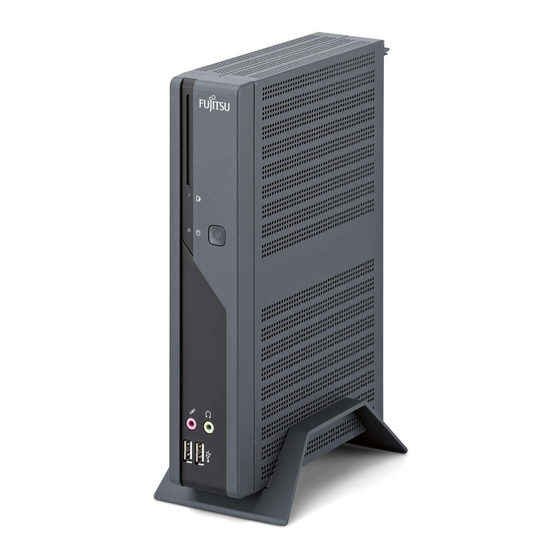
Ihr FUTRO S550... Ihr FUTRO S550... …ist ein universeller Netzwerk-Client. Das intelligente und flexible Terminal ist zuverlässig und leicht zu warten. Der Thin Client benötigt keine Lüfter und keine Festplatte. Dadurch ist er besonders leise im Betrieb. Das Betriebssystem ist auf einem Compact Flash installiert. -
Page 10: Wichtige Hinweise
Wichtige Hinweise Wichtige Hinweise Wichtige Hinweise Hinweise In diesem Kapitel finden Sie unter anderem Sicherheitshinweise, die Sie beim Umgang mit Ihrem Gerät unbedingt beachten müssen. Sicherheitshinweise Sicherheitshinweise Hinweis Beachten Sie die Sicherheitshinweise im Handbuch "Sicherheit" und die nachfolgenden Sicherheitshinweise. Beachten Sie beim Aufstellen und beim Betrieb des Geräts die Hinweise für die Umgebungsbedingungen im Kapitel "Technische Daten ", Seite 25 und das Kapitel... -
Page 11: Gerät Reinigen
Wichtige Hinweise Gerät reinigen Gerät Transport Wiedertransport Systemeinheit,sieheGerät Schalten Sie das Gerät und alle daran angeschlossenen Geräte aus und ziehen Sie den Netzstecker aus der geerdeten Schutzkontakt-Steckdose. Der Gehäuseinnenraum des Geräts darf nur von autorisiertem Fachpersonal gereinigt werden. Verwenden Sie für die Reinigung kein Scheuerpulver und keine Kunststoff lösenden Reinigungsmittel. -
Page 12: Inbetriebnahme
Inbetriebnahme Inbetriebnahme Inbetriebnahme Beachten Sie die Sicherheitshinweise im Kapitel "Wichtige Hinweise", Seite Anschlüsse und Bedienelemente Anschlüsse In diesem Kapitel werden die einzelnen Hardware-Komponenten Ihres Geräts vorgestellt. Sie erhalten eine Übersicht über die Anschlüsse und Bedienelemente des Geräts. Machen Sie sich mit diesen Elementen vertraut, bevor Sie mit dem Gerät arbeiten. Vorderansicht Einschalter Ausschalter... -
Page 13: Rückansicht
Inbetriebnahme Rückansicht RJ45-LAN-Anschluss PS/2-Mausanschluss Einbauplatz PS/2-Tastaturanschluss Bildschirmanschluss SerielleSchnittstelle USB-Anschlüsse Audioausgang Gleichspannungsbuchse Audioeingang PCI-Steckplatz KensingtonLock 1 = Blende 8 = Kensington Lock-Vorrichtung 2 = Serielle Schnittstelle 9 = PS/2-Mausanschluss 3 = Audioausgang (Line out) 10 = Serielle Schnittstelle 4 = USB-Anschlüsse (Universal Serial Bus) 11 = RJ45-LAN-Anschluss (Local Area Network) 5 = Bildschirmanschluss... -
Page 14: Gerät Aufstellen
Inbetriebnahme Gerät aufstellen Damit das Gehäuse ausreichend belüftet wird und um Überhitzung zu vermeiden, darf das Gerät nur mit befestigtem Standfuß betrieben werden. Montieren Sie die Standfüße für waagerechten oder senkrechten Betrieb. Senkrechte Betriebslage SenkrechteBetriebslage Betriebslagesenkrecht Aufstellfüße Seitenteil Benutzen Sie den mitgelieferten Standfuß, wenn Sie das Gerät in senkrechter Betriebslage betreiben wollen. -
Page 15: Waagerechte Betriebslage
Inbetriebnahme Waagerechte Betriebslage Gehen Sie wie folgt vor, um das Gerät in waagrechter Betriebslage zu betreiben: WaagrechteBetriebslage Betriebslagewaagrecht Aufstellfüße ► Lösen Sie gegebenfalls die Leitungen. ► Legen Sie das Gerät auf einer stabilen, ebenen und sauberen Unterlage auf die Oberseite. ►... -
Page 16: Bildschirm Anschließen
Inbetriebnahme Bildschirm anschließen ► Bereiten Sie den Bildschirm vor, wie in der Betriebsanleitung zum Bildschirm beschrieben (z. B. Leitungen stecken). Bildschirm ► Stecken Sie die Datenleitung in den Bildschirmanschluss des Geräts. Je nach Ausbaustufe Ihres Geräts und Ihres Bildschirms, können Sie die Datenleitung auch an die DVI- oder HDMI-Schnittstelle anschließen. -
Page 17: Externe Geräte Anschließen
Inbetriebnahme Externe Geräte anschließen Lesen Sie die Dokumentation zum externen Gerät, bevor Sie es anschließen. Außer bei USB-Geräten müssen die Netzstecker gezogen sein, wenn Sie externe Geräte anschließen! Bei Gewitter dürfen Sie Leitungen weder stecken noch lösen. Fassen Sie beim Lösen einer Leitung immer am Stecker an. Ziehen Sie nicht an der Leitung! Halten Sie beim Anschließen oder Lösen von Leitungen die nachfolgend beschriebene Reihenfolge ein. -
Page 18: Anschlüsse Am Gerät
Inbetriebnahme Anschlüsse am Gerät Schnittstellen ExterneGeräte Gerät Die Anschlüsse finden Sie an Vorder- und Rückseite des Geräts. Welche Anschlüsse an Ihrem Gerät verfügbar sind, hängt davon ab, welche Ausbaustufe Sie gewählt haben. Die Standardanschlüsse sind durch die nachfolgenden oder durch ähnliche Symbole gekennzeichnet. Genauere Angaben zur Position der Anschlüsse finden Sie im Handbuch zum Mainboard. -
Page 19: Externe Geräte An Die Parallele Oder Serielle Schnittstelle Anschließen
Inbetriebnahme Externe Geräte an die parallele oder serielle Schnittstelle anschließen Parallele Schnittstelle SerielleSchnittstelle Parallele Schnittstelle SerielleSchnittstelle ExterneGeräte Geräte An die parallele und die serielle Schnittstelle können Sie externe Geräte anschließen (z. B. einen Drucker oder ein Modem). ► Schließen Sie die Datenleitung an das externe Gerät an. ►... -
Page 20: Mikrofon, Kopfhörer Und Line-Out-Geräte Anschließen
Inbetriebnahme Mikrofon, Kopfhörer und Line-Out-Geräte anschließen Mikrofon Kopfhörer Line-Out-Geräte ► Schließen Sie das Mikrofon an den Mikrofonanschluss an. ► Schließen Sie den Kopfhörer an den Kopfhöreranschluss an. ► Schließen Sie Line-Out-Geräte an den Audioausgang an. ► Schließen Sie Line-In-Geräte an den Audioeingang an. Netzadapter anschließen Netzadapter ►... -
Page 21: Bedienung
Bedienung Bedienung Gerät einschalten ► Schalten Sie gegebenenfalls den Bildschirm ein (siehe Betriebsanleitung des Bildschirms). Gerät Bildschirm ► Schalten Sie das Gerät mit dem Hauptschalter an der Rückseite des Geräts ein (falls vorhanden). ► Drücken Sie den Ein-/Ausschalter an der Vorderseite des Geräts. Die Betriebsanzeige leuchtet grün, das Gerät startet. -
Page 22: Bios-Setup Aufrufen
Bedienung BIOS-Setup aufrufen BIOS-Setup ► Wenn das System startet, drücken Sie (eventuell mehrmals) die Taste Das BIOS-Setup wird gestartet. Sie erreichen weitere Einstellmöglichkeiten im BIOS-Setup, wenn Sie eines der Register auswählen. PXE-Systemstart PXE-Systemstart ► Schalten Sie das Gerät mit dem Ein-/Ausschalter ein. ►... - Page 23 Bedienung Folgende Einstellungen sind möglich: Angabe des verwendeten Systemstart- Protokolls. Network Boot PXE (Standard) Protocol: oder RPL Es wird immer zuerst das Netzwerk gestartet, Boot Order: Int 19h bevor die lokalen Geräte aktiviert werden. Wenn ein BBS-BIOS (BIOS Boot Specification) PnP/ BEV (BBS) vorhanden ist, wird das System durch das BBS-BIOS gestartet.
-
Page 24: Systemerweiterungen
Systemerweiterungen Systemerweiterungen Erweiterungen Gerät Systemerweiterung Optional können Sie folgende Komponenten einbauen: • eine Low-Profile-PCI-Baugruppe (Länge maximal 165 mm) • ein SmartCard-Leser-Modul Es kann sinnvoll sein, wenn Sie sich einige Teile dieses Kapitels ausdrucken, da das Gerät beim Ein-/Ausbau von Systemerweiterungen ausgeschaltet sein muss. Eventuell ist für eine Systemerweiterung oder Hardware-Hochrüstung ein Update des BIOS notwendig. -
Page 25: Gehäuse Öffnen
Systemerweiterungen Gehäuse öffnen Gehäuse Gerät Beachten Sie, dass verschiedene Komponenten auf dem Mainboard sehr heiß sein können, wenn das Gerät vor kurzem noch aktiv war. Diese Komponenten können durch folgendes Symbol gekennzeichnet sein. ► Schalten Sie das Gerät aus. Das Gerät darf sich nicht im Energiesparmodus befinden! Beachten Sie die Sicherheitshinweise im Kapitel "Wichtige Hinweise", Seite Ziehen Sie den Netzstecker aus der Steckdose. -
Page 26: Gehäuse Schließen
Systemerweiterungen Gehäuse schließen Gehäuse Gehäusedeckel ► Setzen Sie den Gehäusedeckel wieder auf das Gerät und schieben Sie ihn nach hinten. ► Befestigen Sie den Gehäusedeckel mit den beiden Schrauben an der Rückseite des Geräts. Achten Sie darauf, dass die Leitungen nicht zwischen Gehäuse und Bauteilen eingeklemmt werden! ►... -
Page 27: Smartcard-Leser Einbauen
Systemerweiterungen SmartCard-Leser einbauen SmartCard-Leser Sie können, sofern nicht bereits vorhanden, einen SmartCard-Leser einbauen. ► Schließen Sie die Leitung am SmartCard-Leser an (1) und schließen Sie die Leitung am Stecker auf dem Mainboard an (2). ► Bauen Sie die Traverse aus (3). ►... -
Page 28: Smartcard-Leser Ausbauen
Systemerweiterungen SmartCard-Leser ausbauen SmartCard-Leser ► Öffnen Sie das Gehäuse (siehe "Gehäuse öffnen", Seite 17). ► Ziehen Sie die Leitung vom SmartCard-Leser (1) und vom Mainboard (2). ► Lösen Sie die Schrauben (3). ► Bauen Sie ggf. die PCI-Baugruppe aus, siehe Kapitel "PCI-Baugruppe ausbauen", Seite ►... -
Page 29: Pci-Baugruppe Einbauen
Systemerweiterungen PCI-Baugruppe einbauen PCI-Baugruppe Sie können nur PCI-Baugruppen mit einer maximalen Länge von 165 mm einbauen. ► Nehmen Sie auf der PCI-Baugruppe die erforderlichen Einstellungen vor. ► Öffnen Sie das Gehäuse (siehe "Gehäuse öffnen", Seite 17). ► Bauen Sie die Traverse aus (siehe "SmartCard-Leser einbauen", Seite ►... - Page 30 Systemerweiterungen Werfen Sie die Rückseitenabdeckung nicht weg. Wenn Sie die PCI-Baugruppe wieder entfernen, müssen Sie die Rückseitenabdeckung wegen der Kühlung, des Brandschutzes und der einzuhaltenden EMV-Vorschriften (Vorschriften zur elektromagnetischen V erträglichkeit) wieder einbauen. ► Stecken Sie Ihre PCI-Baugruppe an die Risercard (1). ►...
-
Page 31: Pci-Baugruppe Ausbauen
Systemerweiterungen PCI-Baugruppe ausbauen PCI-Baugruppe ► Öffnen Sie das Gehäuse (siehe "Gehäuse öffnen", Seite 17). ► Lösen Sie die Schraube (1). ► Lösen Sie die PCI-Baugruppe von der Risercard (2). Sie müssen die Rückseitenabdeckung wegen der Kühlung, des Brandschutzes und der einzuhaltenden EMV-Vorschriften (Vorschriften zur elektromagnetischen Verträglichkeit) wieder einbauen. -
Page 32: Lithium-Batterie Tauschen
Systemerweiterungen Lithium-Batterie tauschen Damit die Systeminformation dauerhaft gespeichert werden kann, ist eine Lithium-Batterie eingebaut, die den CMOS-Speicher mit Strom versorgt. Wenn die Spannung der Batterie zu niedrig oder die Batterie leer ist, wird eine entsprechende Fehlermeldung ausgegeben. Die Lithium-Batterie muss dann ausgetauscht werden. Bei unsachgemäßem Austausch der Lithium-Batterie besteht Explosionsgefahr! Die Lithium-Batterie darf nur durch identische oder vom Hersteller empfohlene Typen ersetzt werden. -
Page 33: Technische Daten
Technische Daten Technische Daten TechnischeDaten Es dürfen nicht mehrere Geräte übereinander gestapelt werden. Thin Client Elektrische Daten Prozessor: AMD Sempron 2100+ Nennspannung: 20 V Maximaler Nennstrom: 3,25 A Abmessungen Breite/Tiefe/Höhe (mit Standfuß): 266 mm/97 mm/191 mm Breite/Tiefe/Höhe (ohne Standfuß): 250 mm/52 mm/191 mm Gewicht im Grundausbau: ca. - Page 34 Technische Daten Netzadapter Elektrische Daten Nennspannung: 100 - 240 V Max. Nennstrom: 1,7 A 50 - 60 Hz Nennfrequenz: Es dürfen nur Adapter mit Limited Power Source werden: • S26113-E519-V55 Model: ADP-65HB AD • S26113-E519-V15 Model: 0335C2065 • S26113-E557-V55 Model: ADP-65JH AD •...
- Page 35 Your FUTRO S550.........
- Page 36 Contents Technical data ............... . 24 English A26361-K528-Z221-1-7419, edition 3...
-
Page 37: Your Futro S550
Your FUTRO S550... Your FUTRO S550... …is a universal network client. The intelligent and flexible terminal is reliable and easy to maintain. The thin client requires no fan and no hard disk. It therefore runs very quietly. The operating system is installed on a compact flash. -
Page 38: Important Notes
Important notes Important notes Importantnotes Notes In this chapter you will find information regarding safety which it is essential to take note of when working with your device. Safety information Safetyinformation Note Pay attention to the information provided in the "Safety" manual and in the following safety notes. -
Page 39: Cleaning The Device
Important notes Cleaning the device Device, Transportation Retransportation System unit,see Device Turn off all power and equipment switches and remove the power plug from the mains supply. Do not clean any interior parts yourself, leave this job to a service technician. Do not use any cleaning agents that contain abrasives or may corrode plastic. -
Page 40: Fcc Class B Compliance Statement
• Consult the dealer or an experienced radio/TV technician for help. Fujitsu Technology Solutions GmbH is not responsible for any radio or television interference caused by unauthorized modifications of this equipment or the substitution or attachment of connecting cables and equipment other than those specified by Fujitsu Technology Solutions GmbH. -
Page 41: Getting Started
Getting started Getting started Gettingstarted Please observe the safety information in the "Important notes", Page 2 chapter. Ports and operating elements Ports This chapter presents the individual hardware components of your device. This will provide you with an overview of the ports and operating elements on the device. Please familiarise yourself with these components before starting to work with your device. -
Page 42: Rear View
Getting started Rear view RJ45-LAN port PS/2mouseport Installationopening PS/2keyboardport Monitorport Serialport USBports Audiooutput DCinputconnector Audioinput PCIslot KensingtonLock 1 = Cover 8 = Kensington Lock 2 = Serial port 9 = PS/2 mouse port 3 = Audio output (Line out) 10 = Serial port 4 = USB ports (Universal Serial Bus) 11 = RJ45 socket (Local Area Network) 5 = Monitor port... -
Page 43: Setting Up The Device
Getting started Setting up the device In order to ensure that the casing is sufficiently ventilated and to prevent overheating, the device must only be operated with the base foot attached. Fit the base feet for horizontal or vertical operation. Vertical operating position Verticaloperatingposition Operatingposition,vertical... -
Page 44: Horizontal Operating Position
Getting started Horizontal operating position Proceed as follows to operate the device in the horizontal operating position: Horizontaloperatingposition Operatingposition,horizontal Base feet ► Disconnect the cables if required. ► Place the device on its upper side on a sturdy, flat and clean surface. ►... -
Page 45: Connecting The Monitor
Getting started Connecting the monitor ► Follow the instructions contained in the monitor manual to prepare the monitor for operation (e.g. connecting cables). Monitor ► Plug the data cable into the monitor port of the device. Depending on the expansion stage of your machine and your monitor, you can also connect the data cable to the DVI or HDMI interface. -
Page 46: Connecting External Devices
Getting started Connecting external devices Read the documentation on the external device before connecting it. With the exception of USB devices, always remove all power plugs before connecting external devices! Do not connect or disconnect cables during a thunderstorm. Always take hold of the actual plug. Never unplug a cable by pulling the cable itself. Connect and disconnect the cables in the order described below. -
Page 47: Ports On The Device
Getting started Ports on the device Interfaces Externaldevices, Device, The ports are located on the front and back of the device. The ports available on your device depend on the configuration level you have selected. The standard ports are marked with the symbols shown below (or similar). Detailed information on the location of the ports is provided in the manual for the mainboard. -
Page 48: Connecting External Devices To The Usb Ports
Getting started Connecting external devices to the USB ports USBdevices, USBport, Externaldevices, Devices, You can connect a wide range of external devices to the USB ports (e.g. printer, scanner, modem or keyboard). USB devices are hot-pluggable. This means you can connect and disconnect USB cables while your device is switched on. -
Page 49: Operation
Operation Operation Switch the device on ► If necessary, switch the monitor on (see the operating manual for the monitor). Device, Monitor, ► Switch on the device using the main power switch located on the rear of the device (if present). ►... -
Page 50: Calling The Pxe System Boot Configuration Menu
Operation Calling the PXE system boot configuration menu ► Press the key combination ↑ while Realtek RTL8139(X)/8130/810X Boot Agent is displayed. The following or a similar display appears on the screen: Realtek RTL 8139 / 8130 / 810x BOOT Agent Configuration Menu v2.13 Network Boot Protokol [RLP]... -
Page 51: System Expansions
System expansions System expansions Upgrades, Device, System expansion You can also install the following optional components: • a low profile PCI board (maximum length of 165 mm) • a SmartCard reader module As the device has to be shut down in order to install/uninstall system hardware components, it is a good idea to print out the relevant sections of this chapter. -
Page 52: Opening The Casing
System expansions Opening the casing Casing, Device, Note that some components on the mainboard may be very hot if the device was in use shortly before the casing was removed. These components can be marked with the following symbol. ► Switch the device off. The device must not be in power-saving mode. Please observe the safety information in "Important notes", Page Disconnect the mains plug from the mains outlet. -
Page 53: Closing The Casing
System expansions Closing the casing Casing Casing cover ► Replace the casing cover on the device and push it backwards. ► Secure the casing cover with the two screws on the rear of the device. Make sure that the cables are not trapped between the casing and the components. ►... -
Page 54: Installing The Smartcard Reader
System expansions Installing the SmartCard reader SmartCardreader If not already installed, you can fit a SmartCard reader. ► Connect the cable to the SmartCard reader (1) and to the connector on the mainboard (2). ► Remove the cross-beam (3). ► If necessary, remove the PCI board, (see "Closing the casing", Page 17). -
Page 55: Removing The Smartcard Reader
System expansions Removing the SmartCard reader SmartCardreader ► Open the casing (see "Opening the casing", Page 16). ► Disconnect the cable from the SmartCard reader (1) and from the mainboard (2). ► Loosen the screws (3). ► If necessary, remove the PCI board (see "Removing the PCI board", Page 22). -
Page 56: Installing The Pci Board
System expansions Installing the PCI board PCIboard You can only install PCI boards with a maximum length of 165 mm. ► Make the required settings for the PCI board. ► Open the casing (see "Opening the casing", Page 16). ► Remove the cross-beam (see "Installing the SmartCard reader", Page ►... - Page 57 System expansions Do not throw away the rear slot cover plate. If you remove the PCI board again, you must reinstall the rear slot cover plate due to cooling, fire protection and the EMC regulations (regulations on electromagnetic compatibility) to be complied with. ►...
-
Page 58: Removing The Pci Board
System expansions Removing the PCI board PCIboard ► Open the casing (see "Opening the casing", Page 16). ► Loosen the screw (1). ► Remove the PCI board from the riser card (2). You must reinstall the rear slot cover plate due to cooling, fire protection and the EMC regulations (regulations on electromagnetic compatibility) to be complied with. -
Page 59: Replacing The Lithium Battery
System expansions Replacing the lithium battery In order to permanently save the system information, a lithium battery is installed to provide the CMOS-memory with a current. A corresponding error message notifies the user when the charge is too low or the battery is empty. The lithium battery must then be replaced. Incorrect replacement of the lithium battery may lead to a risk of explosion! The lithium battery may be replaced only with an identical battery or with a type recommended by the manufacturer. -
Page 60: Technical Data
Technical data Technical data Technicaldata Do not stack several devices on top of each other. Thin Client Electrical data Processor: AMD Sempron 2100+ Rated voltage: 20 V Max. rated current: 3.25 A Dimensions Width/depth/height (with base foot): 266 mm/97 mm/191 mm Width/depth/height (without base foot): 250 mm/52 mm/191 mm Weight in basic configuration:... - Page 61 Technical data Mains adapter Electrical data Rated voltage: 100 - 240 V Max. rated current: 1.7 A 50 - 60 Hz Rated frequency: Only adapters with Limited Power Source may be used: • S26113-E519-V55 Model: ADP-65HB AD • S26113-E519-V15 Model: 0335C2065 •...