Table of Contents
Advertisement
Model 3300L
Installation guide
g
p
NOTE:
This product is intended for installation by a professional installer only!
Any attempt to install this product by any person other than a trained professional
may result in severe damage to a vehicle's electrical system and components.
2008 Directed Electronics, Vista CA N3300L 2008-12
Advertisement
Table of Contents

Related Manuals for Avital 3300L


Summary of Contents for Avital 3300L
- Page 1 Model 3300L Installation guide NOTE: This product is intended for installation by a professional installer only! Any attempt to install this product by any person other than a trained professional may result in severe damage to a vehicle’s electrical system and components.
- Page 2 Code Hopping ® , Doubleguard ® , ESP ® , FailSafe ® , Ghost Switch ® , Learn Routine™, Nite-Lite ® , Nuisance Prevention ® Circuitry, NPC ® Revenger , Silent Mode™, Soft Chirp , Stinger®, Valet , Vehicle Recovery System , VRS , and Warn Away are all Trademarks or Registered...
-
Page 3: Table Of Contents
table of contents what is included ............... . 4 primary harness (H1) wire connection guide. -
Page 4: What Is Included
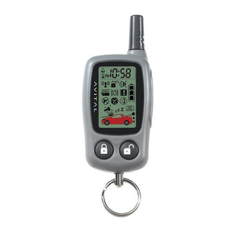
what is included ■ Control module ■ One 4-button remote transmitter ■ Plug-in LED system status indicator ■ One 5-button 2-way LCD remote transmitter ■ An on-board dual zone impact sensor ■ Plug-in Valet/Program switch ■ 12-pin primary harness ■ High-powered siren ■... - Page 5 IMPORTANT! Never use this wire to drive anything but a relay or a low-current input! The transis- torized output can only supply 200 mA of current. Connecting directly to a solenoid, motor, or other high-current device will cause it to fail. H1/2 RED (+)12V constant power input Before connecting this wire, remove the supplied fuse.
- Page 6 H1/4 YELLOW PRIMARY HARNESS TO IGNITION SYSTEM H1/5 BLACK (-) chassis ground connection Remove any paint and connect this wire to bare metal, preferably with a factory bolt rather than a screw. (Screws tend to strip or loosen with time.) We recommend grounding all components, including the siren, to the same point. H1/6 VIOLET (+) door trigger input, zone 3 This wire is used in vehicles that have a positive (+) switched domelight circuit.
- Page 7 H1/8 GREEN (-) door trigger input, zone 3 Most vehicles use negative door trigger circuits. Connect the green wire to a wire which shows ground when any door is opened. In vehicles with factory delays on the domelight circuit, there is usually a wire that is unaffected by the delay circuitry.
- Page 8 H1/11 WHITE (+/-) selectable light flash As shipped, this wire should be connected to the (+) parking light wire. If the light flash polarity jumper inside the control module is moved to the opposite position (see Internal Programming Jumper section of this guide), this wire supplies a (-) 200 mA output.
-
Page 9: Door Lock Harness (H2) Wire Connection Guide
door lock harness (H2) wire connection guide ______ VIOLET* LOCK RELAY, NORMALLY OPEN H2/A ______ BLUE/BLACK LOCK RELAY, COMMON H2/B ______ BROWN/BLACK LOCK RELAY, NORMALLY CLOSED H2/C ______ VIOLET/BLACK* UNLOCK RELAY, NORMALLY OPEN H2/D ______ GREEN/BLACK UNLOCK RELAY, COMMON H2/E ______ WHITE/BLACK UNLOCK RELAY, NORMALLY CLOSED... -
Page 10: At The Switch
There are eight common types of door lock circuits (some vehicles use more unusual systems): ■ Type A: Three-wire (+) pulse controlling factory lock relays. Most GM, some Ford and Chrysler, 1995 Saturn, some new VW, newer BMW. ■ Type B: Three-wire (-) pulse controlling factory lock relays. Most Asian vehicles, early Saturn, some BMW and Porsche. -
Page 11: Type A: Positive-Triggered, Relay-Driven System
type A: positive-triggered, relay-driven system The system can control Type A door locks directly, with no additional parts. The switch will have three wires on it, and one will test (+)12V constantly. The others will alternately pulse (+)12V when the switch is pressed to the lock or unlock position. -
Page 12: Type B: Negative-Triggered, Relay-Driven System
type B: negative-triggered, relay-driven system This system is common in many Toyota, Nissan, Honda, and Saturn models, as well as Fords with the keyless- entry system (some other Fords also use Type B). The switch will have three wires on it, and one wire will test ground all the time. One wire will pulse (-) when the switch locks the doors, and the other wire will pulse (-) when the switch unlocks the doors. -
Page 13: Type C: Reversing Polarity System
type C: reversing polarity system 2008 Directed Electronics, Vista CA - all rights reserved... -
Page 14: Type D: Adding One Or More After-Market Actuators
type D: adding one or more after-market actuators Vehicles without factory power door locks require the installation of one actuator per door. This requires mount- ing the door lock actuator inside the door. Other vehicles may only require one actuator installed in the driver's door if all door locks are operated when the driver's lock is used. -
Page 15: Type E: Electrically-Activated Vacuum
type E: electrically-activated vacuum This system is found in some older Mercedes-Benz and Audi. The door locks are controlled by an electrically acti- vated vacuum pump. The control wire will show (+)12V when doors are unlocked and (-) ground when locked. NOTE: The system must be programmed for 3.5-second door lock pulses, and the violet jumper between the #87 lock terminal and the #87 unlock terminal must be cut. -
Page 16: Type F: One-Wire System (Cut To Lock, Ground To Unlock)
type F: one-wire system (cut to lock, ground to unlock) This type of door lock system usually requires a negative pulse to unlock, and cutting the wire to lock the door. (With some vehicles, these are reversed.) It is found in some older Nissan Sentras, Nissan 240SX, and Nissan 300ZX. -
Page 17: Type G: Positive (+) Multiplex
type G: positive (+) multiplex This system is most commonly found in Ford, Mazda, Chrysler and GM vehicles. The door lock switch or door key cylinder may contain either one or two resistors. SINGLE-RESISTOR TYPE: If one resistor is used in the door lock switch/key cylinder, the wire will pulse (+)12V in one direction and less than (+)12V when operated in the opposite direction. - Page 18 Vehicle Fused +12 volt constant (+)12v Constant Fused 2008 Directed Electronics, Vista CA - all rights reserved...
-
Page 19: Type H: Negative (-) Multiplex
type H: negative (-) multiplex The system is most commonly found in Ford, Mazda, Chrysler and GM vehicles. The door lock switch or door key cylinder may contain either one or two resistors. SINGLE-RESISTOR TYPE: If one resistor is used in the door lock switch/key cylinder, the wire will pulse ground in one direction and resistance to ground when operated in the opposite direction. -
Page 20: Auxiliary Harness (H3) Wire Connection Guide
auxiliary harness (H3) wire connection guide ______ VIOLET/BLACK (-) 200 mA CHANNEL 4 OUTPUT H3/1 ______ BROWN/BLACK (-) 200 mA HORN HONK OUTPUT H3/2 ______ BLUE (-) 200 mA SECOND UNLOCK H3/3 H3/1 VIOLET BLACK (-) 200mA channel 4 output This wire supplies a (-)200mA output whenever the button(s) controlling channel four is pressed and will con- tinue until the button(s) is released. - Page 21 H3/3 BLUE (-) 200mA second unlock output This output is used for progressive door unlock. A progressive unlock system unlocks the driver's door when the unlock (disarm) button is pressed and unlocks the passenger doors if the unlock (disarm) button is pressed again within 15 seconds after unlocking the driver's door.
-
Page 22: Starter Interrupt Harness (H4) Wire Connection Guide
Driver’s Door Unlock Only (Type B): H3/3 BLUE (-) 200 A SECOND UNLOCK OUTPUT DRIVER’S DOOR LOCK (+)12V UNLOCK MOTOR MOTOR H2/A VIOLET UNLOCK #87 NORMALLY OPEN (INPUT) CONSTANT #87A UNLOCK H2/B BLUE/BLACK UNLOCK #30 COMMON (OUTPUT) RELAY H2/C BROWN/BLACK UNLOCK #87A NORMALLY CLOSED FACTORY RELAY... -
Page 23: Plug-In Led And Valet/Program Switch
plug-in LED and valet/program switch The LED and the Valet/Program switch both plug into the control module. The LED system status indicator plugs into the white two-pin port, while the Valet/Program switch should be plugged into the blue two-pin port. The LED and Valet/Program switch each fit into -inch holes. -
Page 24: Internal Programming Jumper
internal programming jumper NOTE: JUMPER IS INSIDE THE CASE light flash jumper This jumper is used to determine the light flash output. In the (+) position, the on-board relay is enabled and the unit will output (+)12V on the H1/11 WHITE wire. In the (-) position, the on-board relay is disabled. The H1/11 WHITE wire will supply a (-) 200 mA output suitable for driving factory parking light relays. -
Page 25: On-Board Dual Stage Impact Sensor
on-board dual stage impact sensor There is a dual-stage impact sensor inside the control unit. Adjustments are made via the rotary control as indi- cated above. Since the impact sensor does not work well when mounted firmly to metal, we recommend against screwing down the control module. -
Page 26: Transmitter/Receiver Learn Routine
transmitter/receiver learn routine The system comes with two transmitters that have been taught to the receiver. Use the following learn routine to add transmitters to the system or to change button assignments if desired. The Valet/Program switch, plugged into the blue port, is used for programming. There is a basic sequence to remember whenever programming this unit: Door, Key, Choose, Transmit and Release. -
Page 27: 4-Button Transmitter Configuration
Transmit. While HOLDING the Valet/Program switch, press the transmitter button that you wish to assign to that channel. The unit will chirp indicating successful programming. Release. Once the code is learned, the Valet/Program switch can be released. You can advance from one channel to another by releasing the Valet/Program switch and tapping it to advance channels and then HOLDING it. -
Page 28: Lcd 2-Way Transmitter Additional Controls
LCD 2-way transmitter additional controls The LCD 2-way transmitter has the following additional controls: operates No function operates Remote extended functions/LCD backlight operates Battery Saver Mode operate Beep/Vibrate Notification operate Time/Alarm Display operates Parking Timer 2008 Directed Electronics, Vista CA - all rights reserved... -
Page 29: System Features Learn Routine
system features learn routine Many of the features of this unit are programmable. They can be changed whenever necessary through this learn routine. The Valet/Program switch, plugged into the blue port, is used together with a programmed transmitter to change the settings. To enter the feature learn routine: Open a door. -
Page 30: Features Menu
To exit the Code Learning, do one of the following: ■ The doors are closed. ■ Turn the ignition on. ■ No activity for longer than 15 seconds. ■ Press the Valet/Program switch too many times. features menu FEATURE DEFAULT LED ON SETTINGS LED OFF SETTINGS NUMBER (PRESS LOCK ICON TRANSMITTER BUTTON) (PRESS UNLOCK ICON TRANSMITTER BUTTON) - Page 31 3 IGNITION-CONTROLLED DOOR LOCK/UNLOCK ON/OFF: When turned on, the doors will lock three seconds after the ignition is turned on and unlock when the ignition is turned off. If the ignition key is turned on while the vehicle door(s) are open, the door(s) will not lock. 4 ACTIVE/PASSIVE LOCKING: If passive arming is selected in Feature 1, then the system can be programmed to either lock the doors when passive arming occurs, or only lock the doors when the system is armed with the transmitter.
-
Page 32: Nuisance Prevention® Circuitry
10 Comfort closure feature: This feature is designed to integrate with vehicles that can close the power windows and sunroof by holding the key in the driver door lock position, and will operate on both single input systems and two pulses input dead bolt systems. If programmed on the door lock output will activate the Comfort Close output for 20 seconds. -
Page 33: Table Of Zones
table of zones When using the Diagnostic functions, use the Table of Zones to see which input has triggered the system. It is also helpful in deciding which input to use when connecting optional sensors and switches. ZONE NO. TRIGGER TYPE INPUT DESCRIPTION Multiplex H1/7 BLUE wire. - Page 34 ■ Door input does not respond with the progressive trigger, but with immediate full alarm: Does the LED indicate that the trigger was caused by the impact sensor? (See Table of Zones section of this guide.) The impact sensor, if set to extreme sensitivity, may be detecting the door unlatching before the door switch sends its signal.
-
Page 35: Wiring Quick Reference Diagram
wiring quick reference diagram 2008 Directed Electronics, Vista CA - all rights reserved...