Table of Contents
Advertisement
Responder LE Model 5701
Security and Remote Start
Installation Guide
Note: This product is intended for installation by a professional installer
only! Any attempt to install this product by any person other than a trained
professional may result in severe damage to a vehicle's electrical system and
components
.
© 2008 Directed Electronics, Vista, CA
N5202V 2008-02
Advertisement
Table of Contents

Related Manuals for Viper Responder LE 5701


Summary of Contents for Viper Responder LE 5701
-
Page 1: Installation Guide
Responder LE Model 5701 Security and Remote Start Installation Guide Note: This product is intended for installation by a professional installer only! Any attempt to install this product by any person other than a trained professional may result in severe damage to a vehicle’s electrical system and components ©... - Page 2 Bitwriter®, Code Hopping™, Doubleguard®, ESP™, FailSafe®, Ghost Switch™, Learn Routine™, Nite-Lite®, Nuisance Prevention® Circuitry, Revenger®, Silent Mode™, Soft Chirp®, Stinger®, Valet®, Vehicle Recovery System®, VRS®, and Warn Away® are all Trademarks or Registered Trade- marks of Directed Electronics. The Bitwriter (p/n 998U) ®...
-
Page 3: Table Of Contents
Table of contents What is included . . . . . . . . . . . . . . . . . . . . . . . . . . . . . . 5 Warning! Safety first . - Page 4 Remote control learn routine . . . . . . . . . . . . . . . . . . . . . 56 Remote control configuration .
-
Page 5: What Is Included
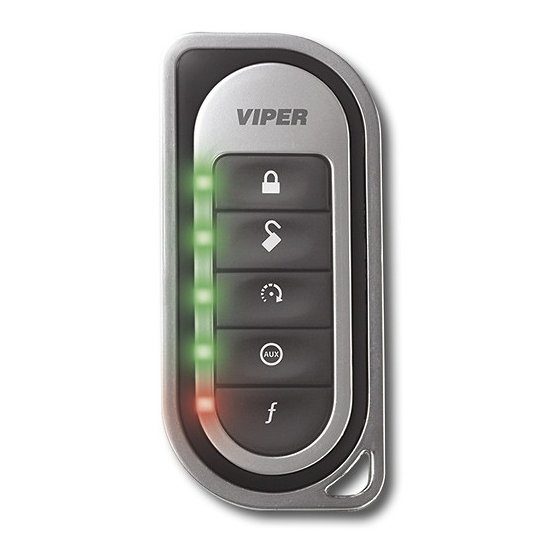
What is included The control module with Stinger™ DoubleGuard® two-stage shock sensor Control center (installed out of sight) with integrated status LED and Valet Override switch (p/n 6211T) One five-button/2-way Supercode Responder LE Remote Control, (p/n 7251V) ... -
Page 6: Warning! Safety First
Warning! Safety first The following safety warnings must be observed at all times: Due to the complexity of this system, installation of this product must only be performed by an authorized Directed Electronics dealer. When properly installed, this system can start the vehicle via a command ... - Page 7 After the remote start module has been installed, test the remote start module in accordance with the Safety Check outlined in this installation guide . If the vehicle starts when performing the Neutral Safety Shutdown Circuit test, the remote start unit has not been properly installed . The remote start module must be removed or properly reinstalled so that the vehicle does not start in gear .
-
Page 8: Installation Points To Remember
Installation points to remember This product is designed for fuel-injected, automatic transmission, or vehicles with manual transmissions. Note: The default option “Manual” is a safety precaution that forces the installer to enable the Manual Transmission Mode (MTS) routine or program the unit to the “Automatic”... -
Page 9: After The Installation
After the installation Test all functions. The “Using Your System” section of the Owner's Guide is very helpful when testing. When testing, don’t forget that this system is equipped with Nuisance Prevention® Circuitry (NPC). NPC can bypass trigger zones, making them appear to stop working. -
Page 10: Deciding On Component Locations
Deciding on component locations Siren Some things to remember about mounting the siren: ■ Keep it away from heat sources, such as radiators, exhaust manifolds, turbo- chargers, and heat shields. ■ Mount it where a thief cannot easily disconnect it, whether the hood is open or shut. -
Page 11: Control Module
Control module Some things to remember about where to mount the control module: ■ Never put the control module in the engine compartment! ■ The first step in hot-wiring a vehicle is removing the driver's side under-dash panel to access the starter and ignition wires. If the control module is placed just behind the driver's side dash it can easily be disconnected. -
Page 12: Status Led
The control center The control center position should be discussed with the vehicle’s owner prior to installation. The LED and Valet switch is housed on the control center, so you will want to make sure that the customer is satisfied with the location. Doubleguard shock sensor Since the shock sensor is built into the main unit, be sure to keep the shock sensor performance in mind when deciding on a location for the main unit. -
Page 13: Finding The Wires You Need
Finding the wires you need Now that you have decided where each component will be located, you are ready to find the wires in the car that the security system connects to. Important! Do not use a 12V test light or logic probe (computer safe test light) to find these wires! Use a digital multi meter for all testing. - Page 14 How to find (+)12V ignition with your multi meter: Set to DCV or DC voltage (12V or 20V is fine). Attach the (-) probe of the meter to chassis ground. Probe the wire you suspect of being the ignition wire. The steering column harness or ignition switch harness is an excellent place to find this wire.
- Page 15 Starter wire The starter wire provides 12V directly to the starter or to a relay controlling the starter. In some vehicles, it is necessary to power a cold start circuit. A cold start circuit will test exactly like a starter circuit, but it does not control the starter. Instead, the cold start circuit is used to prime the fuel injection system for start- ing when the vehicle is cold.
- Page 16 Accessory wire An accessory wire shows +12V when the key is in the accessory and run positions. It does not show +12V during the cranking cycle. There are often more than one ac- cessory wire in the ignition harness. The correct accessory wire powers the vehicle's climate control system.
- Page 17 Wait-to-start bulb wire for diesels Note: The system has a programmable onboard timer (See Menu#3 Feature 9), so it is not necessary to connect the wait-to-start wire. In diesel vehicles you can interface with the wire that turns on the WAIT-TO- START light in the dashboard.
- Page 18 How to find a (+) or (-) parking light wire with your multi meter: Set to DCV or DC voltage (12V or 20V is fine). If you are looking for a positive circuit attach the (-) probe of the meter to chassis ground.
- Page 19 Door pin switch circuit The best places to test for the door switch wire are: Pin switch When testing at the pin switch, check the wire to ensure that it “sees” all the doors. Often, the passenger switch will cover all the doors even if the driver’s switch will not.
-
Page 20: Making Your Wiring Connections
Making your wiring connections Before making your connections, plan how your wires will be routed through the vehicle. For instance, the red 12V constant input and the remote start ignition wires will often be routed together to the ignition switch harness. In order to keep the wiring neat and make it harder to find, you may wish to wrap these wires together in electrical tape or conceal them in tubing similar to what the manufacturer used. -
Page 21: Primary Harness (H1), 12-Pin Connector
Primary harness (H1), 12-pin connector RED/WHITE (-) 200mA TRUNK RELEASE OUTPUT H1/1 (+)12v CONSTANT INPUT H1/2 BROWN (+) SIREN OUTPUT H1/3 WHITE/ LIGHT FLASH -ISOLATION WIRE - PIN 87a of H1/4 BROWN onboard relay BLACK (-) CHASSIS GROUND H1/5 VIOLET (+) DOOR TRIGGER INPUT H1/6 BLUE... -
Page 22: Door Lock Harness, 3-Pin Connector
Door lock harness, 3-pin connector BLUE (+) LOCK (-) UNLOCK OUTPUT EMPTY NOT USED GREEN (-) LOCK (+) UNLOCK OUTPUT There are three harness connections relative to remote start function, including the heavy gauge and input and output harnesses. Heavy gauge remote start, (H3) 10-pin connector PINK (+) IGNITION 1 INPUT/OUTPUT... -
Page 23: Remote Start Auxiliary Output, 5-Pin
Remote start auxiliary output, 5-pin PINK/WHITE (-) 200mA FLEX RELAY CONTROL OUTPUT ORANGE (-) 200mA ACCESSORY OUTPUT VIOLET (-) 200mA STARTER OUTPUT PINK (-) 200mA IGNITION 1 OUTPUT BLUE (-) 200mA STATUS OUTPUT Note: Wires 1 - 4 on the remote auxiliary outputs are wired to the (-) triggers for the onboard remote start relays and are not diode isolated. -
Page 24: Wire Connection Guides
Wire connection guides Primary harness (H1) H1/1 RED/WHITE Aux/Trunk release , 200mA (-) outputt When the system receives the code controlling trunk release output for longer than 1.5 seconds, the red/white wire will supply an output as long as the trans- mission continues. - Page 25 H1/3 BROWN (+) Siren output Connect this to the red wire of the siren. Connect the black wire of the siren to (-) chassis ground, preferably at the same point you connected the control module’s black ground wire. H1/4 WHITE/BROWN - Onboard light flash relay This wire connects to pin 87a of the onboard light flash relay.
- Page 26 H1/5 BLACK (-) Chassis ground connection We recommend that you do not use a factory ground. Ground all your components including the siren, to the same point in the vehicle, (preferably the kick panel). Scrape away any paint and use a factory bolt or make your own ground with a self-tapping screw and a star washer.
- Page 27 H1/6 VIOLET (+) Door trigger input, zone 3 This wire is used in vehicles that have a positive (+) switched dome light circuit. Connect the violet wire to a wire that shows (+)12V when any door is opened, and ground when the door is closed. This wire will report Zone 3. H1/7 BLUE (-) Trunk pin /instant trigger input, zone 1 This input will respond to a negative input with an instant trigger.
- Page 28 H1/9 BLACK/WHITE (-) 200 mA dome light supervision output Connect this wire to the optional dome light supervision relay as shown below: Important! This output is only intended to drive a relay. It cannot be connected directly to the dome light circuit, as the output cannot support the current draw of one or more light bulbs.
- Page 29 H1/11 WHITE Parking light output This wire should be connected to the parking light wire in the vehicle. See Setting the light flash polarity section of this guide for polarity settings. (+) Positive Light Flash Output (-) Negative Light Flash Output Note: For parking light circuits that draw 10 amps or more, the internal jumper must be switched to a (-) light flash output.
-
Page 30: Auxiliary Harness (H2)
Auxiliary harness (H2) H2/1 LIGHT GREEN/BLACK (-) Factory alarm Disarm This wire sends a negative pulse every time the remote start is activated , chan- nel 2 is activated (programmable on/off) or when the doors are unlocked with the remote. This can be used to pulse the disarm wire of the vehicle's factory anti- theft device. - Page 31 H2/4 VIOLET/BLACK 200 mA (-) programmable Aux 2 output This wire provides 200 mA programmable output whenever the transmitter but- tons controlling Aux 2 channel is pressed. (See descriptions for Aux 3.) Warning! Never use this wire to drive anything but a relay or a low-cur- rent input! This transistorized output can only supply 200 mA.
- Page 32 H2/6 LIGHT BLUE (-) 200mA 2nd unlock output This wire produces a (-) 200mA output for progressive locks in which the driver door unlocks first and the remaining locks will unlock with a second press of the unlock button on the remote. Note: This feature will need to be programmed “On”...
- Page 33 (+)WAIT-TO-START WIRE H2/8 BROWN/BLACK (-) Horn honk output This wire is a low current output (200mA) and can be hooked to the horn honk wire in the vehicle. It can be programmed to sound only during full trigger or to be used like a siren output with arm/disarm chirps. Refer to System Features Menu#1, Feature 10 for more information.
-
Page 34: Door Lock Wire Diagrams
Door lock wire diagrams Important! Depending on the vehicle, the door locks may be controlled by an optional data bus expansion module. If so, no door lock interface wiring is required. There are eight different types of door lock systems (Type A - H). Refer to the vehicle-specific wiring instructions on the web and the chart below to help determine which door lock system your vehicle uses. - Page 35 Type A: Three-wire (+) pulse controlling factory lock relays The system can control Type A door locks directly, with no additional parts. The switch will have three wires on it; one will test (+)12 volt constantly. The others will alternately pulse (+)12 volt when the switch is pressed to the lock or unlock position.
- Page 36 (-) CHASSIS POWER DOOR GROUND LOCK SWITCH LOCK UNLOCK GREEN LOCK OUTPUT BLUE UNLOCK OUTPUT FACTORY RELAYS This system works similar to the Type A system, but uses a negative to control the relays in the vehicle. Note: If your locks operate in the reverse, (lock when pressing unlock, and unlock when pressing lock) then switch the lock/unlock wires and the locks will operate correctly.
- Page 37 Type C: Direct-wired reversing polarity switches Interfacing with a reversing polarity system requires either two relays OR one DEI 451M (not included). It is critical to identify the proper wires and locate the master switch to interface the door locks properly. This door lock system will be referenced on our vehicle specific wiring information sheet as a system.
- Page 38 Caution: If these wires are not connected properly, you will send (+) 12 volts directly to (-) ground, possibly damaging the alarm or the factory switch. Type D: Adding one or more aftermarket actuators In order for this system to control one or more aftermarket actuators, a DEI 451M (not included) or two relays are required.
- Page 39 Type E: Electrically-activated vacuum systems Type E door locks are controlled by an electrically activated vacuum pump. Some Mercedes and Audis use the Type E system. The control wire can be found in either kick panel and will show (+)12 volts when doors are unlocked and (-) ground when doors are locked and when turning the key in the driver or passenger door.
- Page 40 Type F: One-wire system - cut to lock, ground to unlock Type F door locks usually require a negative pulse to unlock and cutting the wire to lock the door. In some vehicles, these functions are reversed. One relay (not included) is used to interface to this type of system.
- Page 41 Type G: Positive (+) multiplex The door lock switch or door key cylinder may contain either one or two resis- tors that will trigger the lock control module through a positive resisted pulse. When interfacing with this type of door lock system, two relays or a DEI 451M must be used.
- Page 42 Type H: Negative (-) multiplex The door lock switch or door key cylinder may contain either one or two resistors. When interfacing with this type of door lock system, two relays or a DEI 451M must be used. GREEN BLUE Single-Resistor Type If one resistor is used in the door lock switch/key cylinder, the wire will pulse ground in one direction and resistance to ground when operated in the opposite...
- Page 43 Determining the Proper Resistor Values To determine the resistor values, the door lock switch/key cylinder must be iso- lated from the factory door lock system. For all testing, use a calibrated digital multi meter that is set to ohms. Cut the output wire from the door switch/key cylinder in half. Test with one meter probe on the switch side of the cut wire, if testing for a positive circuit place the other probe to a constant (+)12V source.
-
Page 44: Heavy Guage, 10-Pin Connector
Heavy Gauge, 10-pin connector There are 9 heavy gauge wires coming from the large 10-pin connector. They are used to energize the ignition circuits in the vehicle. It is crucial that these con- nections are well made and capable of handling the current demands. For this rea- son, Scotch-Locks, T-taps and other such connectors are strongly discouraged. -
Page 45: Remote Start Input-5-Pin Connector
H3/8 PINK/BLACK – 87a of Ignition 2/Flex relay. This wire is used when an ignition switch isolation on the vehicle is necessary. This is common on Toyota and Nissans which required the use of Tech Tip docu- ment #1077. (See menu # 3 Feature 8 for programming options) 30a fused accessory/starter relay input H3/9 RED/BLACK –... - Page 46 Brake shutdown input BROWN (+) This wire MUST be connected to the vehicle’s brake light wire. This is the wire that shows (+) 12V when the brake pedal is depressed. The remote start will be disabled or shut down any time the brake pedal is depressed. Note: This wire MUST be used when installing this unit on a manual transmission.
-
Page 47: Outputs For Optional External Remote Start Relays
Outputs for optional ext. remote start relays These signals are provided to drive additonal optional relays. (-) 200mA Flex Relay Control Output PINK/WHITE This wire is programmed as (-) 2nd ignition output from factory and can be pro- grammed (to drive a relay) as a (-) starter or accessory output. (-) 200mA Accessory output ORANGE This wire works like the main accessory wire and can be used (with a relay) to... -
Page 48: Neutral Safety Switch Interface
Neutral safety switch interface Some vehicles do not have an electrical neutral safety switch. Instead, the ve- hicle has a mechanical neutral safety switch that physically interrupts the starter wire and is used when the vehicle is in any drive gear. If the remote start is interfaced before this switch, it will provide protection from starting in gear. -
Page 49: Testing The Neutral Safety Switch
Testing the neutral safety switch Make sure there is adequate clearance to the front and rear of the vehicle because it may move slightly. Make sure the hood is closed and there are no remote start shut-downs active. Set the emergency brake. Turn the key to the "run"... - Page 50 However, due to future manufacturer changes in vehicles, it is possible that this may not apply to all vehicles. In addition, color variations are possible from model to model; make sure to test the circuit carefully. Please call Directed Electronics Technical Support if you need assistance in making this interface.
-
Page 51: Plug-In Led And Valet/Program Switch
Plug-in LED and valet/program switch The LED and valet switch are incorporated into the control center the LED line will plug into the white 2-pin port and the Valet switch line will plug into the blue 2-pin port. Note: Onboard LED and valet switch can be substituted with an optional out- board LED (P/N 8634 for Blue LED and 8633 for red LED) and an outboard valet switch (P/N 8631). -
Page 52: Optional Sensor Port - 4 Pin Connector
Optional sensor port - 4-pin connector Note: There is a shock sensor built onboard the main unit. This connector is an optional sensor port to add sensors to the security system. Optional sensors that may be used are: 508D Doubleguard Proximity Field Dis- turbance, 509U Ultrasonic Sensor, 506T Glass Break Sensor, and 507M Digital Tilt Sensor. -
Page 53: Tach Learning
Tach learning To learn the tach signal: 1. Start the vehicle with the key. 2. Within 5 seconds, press and hold the Valet/Program switch. 3. After 3 seconds the LED will light constant when the tach signal is learned. 4. Release the Valet/Program switch. -
Page 54: D2D Jumper Settings
Tach threshold On/Off In most cases, this jumper can be left in the OFF position. Some new vehicles use less than 12 volts in their ignition systems. The unit may have trouble learning the tach signal in these vehicles. Changing the jumper to the ON set- ting changes the trigger threshold of the digital tach circuit so it will work properly with these vehicles. -
Page 55: Setting The Light Flash Polarity
Setting the light flash polarity Light flash (+) / (-) polarity The internal fuse is used to determine the light flash output. In the (+) position, the onboard relay will output (+)12V on the WHITE wire, H1/11. In the (-) posi- tion, the on-board relay will supply a (-) output When wiring into a multiplex circuit, you can replace the fuse with a resistor (paying attention to the polarity setting). -
Page 56: Remote Control Learn Routine
Remote control learn routine ™ The remote uses a Supercode Protocol so the remote will need to be setup before programming the system. To enter the remote setup mode you will need to hold the “function” button on the remote until the remote gives a long beep and the transmit LED comes on solid (approximately 8 seconds). - Page 57 3 . Choose Within 10 seconds, press and release the Program switch corresponding to the number of the desired function step listed in the following table. Once you have selected the function step, press the switch once more and hold it. The LED will flash and the siren will chirp to con- firm the selected functional step.
-
Page 58: Remote Control Configuration
You can advance from one function step to another by releasing the Valet/Pro- gram switch and tapping it to advance function steps and then HOLDING it. Learn Routine is exited if: ■ The door is closed ■ The ignition is turned off ■... - Page 59 The remote control buttons that operate the features of the security and remote start system are described below. The buttons will operate in this configuration when the remote control is programmed using the Step 1 Auto-learn routine. REMOTE CONTROL FUNCTIONS TABLE Level Button ARMED...
-
Page 60: System Features Learn Routine
System features learn routine The System Features Learn Routine dictates how the unit operates. It is possible to access and change any of the feature settings using the Valet/program switch. However, this process can be simplified by using the Bitwriter®. Any of the settings can be changed and then assigned to one of four remote controls. - Page 61 4 . Select a Feature . Press and release the Valet/Program switch the number of times corresponding to the feature you wish to change. For example, to access the third fea- ture, press and release 3 times. Then press the button once more and HOLD it.
- Page 62 To access another feature in the same menu: Press and release the Valet/Program switch the number of times necessary to advance from the feature you just programmed to the next one you want to program. Then press the Valet/Program switch once more and hold it. For example, if you just programmed the third feature in the menu and you want to program the seventh feature in the menu, press and release the Valet/Program switch four times and then press it once more and hold it.
-
Page 63: Feature Menus
Feature menus Menu 1 - Security features The default settings are indicated in type. bold Opt . 1 Menu Item Feature Opt . 2 Opt . 3 Opt .4 Opt . 5+ Active System Arm- Passive Arm Passive Arm Auto re-arm Auto Re-arm w/o lock w/lock... - Page 64 Menu 2 - Convenience features Menu Item Feature Opt . 1 Opt . 2 Opt . 3 Opt .4 Opt . 5+ One-time No Bypass Bypass Nuisance Prevention Valet Switch Pulse Count Door Trigger Error Chirp Ign-controlled Dome light OEM Alarm Disarm w/Ch2 OEM Alarm With...
- Page 65 Menu 3 - Remote start features Menu Item Feature Opt . 1 Opt . 2 Opt . 3 Opt .4 Opt . 5 Manual Transmission Automatic Mode Engine Virtual Voltage Tachometer Checking Tach Mode Cranking 0 .6 sec 0.8 sec 1.0 sec 1.2 sec 1.4 (5)/1.6(6)/...
-
Page 66: Feature Descriptions
Feature descriptions The features of the system are described below. Features that have additional settings that can be selected only when programming with the Bitwriter® are indicated by the following icon: Menu 1 - Security features Default settings are in bold . Note: The numbers in parentheses indicate the number of times the LED on the antenna will flash. - Page 67 1-5 IGNITION LOCKS OFF : (1) When turned OFF the alarm will not lock/unlock the doors when ignition is turned on/off. (2) When turned ON the doors will lock three seconds after the ignition is turned ON and the vehicles doors are closed, and will unlock when the ignition is turned OFF.
- Page 68 1-9 COMFORT CLOSURE OFF(1): The system can be programmed to close the windows when the system is armed. If programmed ON, the lock output provides a 20 second pulse when the system is locked. The output will be cancelled if the unlock button is pressed.
- Page 69 Menu 2 - Convenience features Default settings are in bold. 2-1 One time bypass OFF: One time bypass ON. When programmed On the unit will not passively arm for one cycle when turning the ignition on and off within 3 seconds.
- Page 70 2-5 IGNITION CONTROLLED DOME LIGHT SUPERVISION ON: If turned on, the system will turn on the dome light for 60 seconds when the ignition is turned off. The optional dome light supervision feature must be installed as described in the Wire Connection Guide. Use the two-chirp setting for: Ignition controlled dome light OFF.
- Page 71 2-10 Channel 1 Linking, None (1) Arm (2) Disarm (3) Arm/Disarm (4) Remote Start (5). When programming to Validity or timed output this can be programmed to activate when arming or disarming (or remote start) with the transmitter. 2-11 Channel 2 Validity (1) Latched (2), Latch reset w/ignition (3), 30-sec. timed, (4) Output, (5) Off.
- Page 72 3-2 ENGINE CHECKING VIRTUAL TACH: (1) When set to “virtual tach” the re- mote start will monitor the cranking voltage of the vehicle and set that voltage as a reference point. Fifteen seconds after the crank output sequence the remote start checks the voltage again to determine if the vehicle is running.
- Page 73 To activate manually a push button needs to be hardwired to the (-) activation input on the remote start unit. When the vehicle is running press the button the appropriate amount of times to activate the remote start (factory setting is for 1 pulse).
- Page 74 3-11 2nd STATUS OUTPUT: NORMAL: This feature allows selection of status out- put or a rear defogger mode that turns on ten seconds after the vehicle has started, if the vehicle interior temperature is below 55 degrees F. The defogger mode has two selections, latched, the LED will flash twice, or pulsed, the LED will flash three times.
- Page 75 Bitwriter® features The Bitwriter® has the ability to fine tune certain features of the security system. These features and the adjustments that may be programmed are de- scribed in the table below. Feature Default Optional settings setting Siren duration 30 seconds 1- 180 seconds Channel 3 timed output 30 seconds...
-
Page 76: Nuisance Prevention Circuitry
Nuisance prevention circuitry NPC requires that you change the way you test the system since NPC will bypass an input zone for 60 minutes. If the system “sees” the same zone trigger three times, and the triggers are spaced less than an hour apart, the system will bypass that input zone for 60 minutes. -
Page 77: Valet Mode
Valet mode To enter or exit valet mode with the valet/program switch: 1. Turn the ignition key on and then off. 2. At anytime during the next 10 seconds, press and re- lease the Valet switch. Now the Status LED will light con- stantly if you have entered Valet®... -
Page 78: Manual Transmission Remote Start
Manual transmission remote start If the vehicle has manual transmission the proper steps must be followed before leaving the parked vehicle or the remote start feature is disabled. Make sure the doors on the vehicle are closed. Put the transmission in neutral. Press on the brake in the vehicle. -
Page 79: Timer Mode
Timer Mode This unit can be programmed to start and run the engine every three hours, for a maximum of six cycles. The engine will run for the programmed run time and then shut down. After three hours, the system will restart the engine. Important! Timer Mode should be used only in open areas. -
Page 80: Long Term Event History
Long term event history The system stores the last two full triggers in memory. These are not erasable. Each time the unit sees a full trigger, the older of the two triggers in memory will be replaced by the new trigger. To access long term event history: 1. -
Page 81: Table Of Zones
Table of zones When using the Diagnostic functions, use the Table of Zones to see which input has triggered the system. It is also helpful in deciding which input to use when connecting optional sensors and switches. ZONE NO . TRIGGER TYPE INPUT DESCRIPTION Trunk Input... -
Page 82: Shutdown Diagnostics
Shutdown diagnostics To perform shutdown diagnostics With the ignition OFF, press and the Valet/Program switch. HOLD Turn the ignition ON and then back OFF while the Valet/Program HOLDING switch. Release the Valet/Program switch. Press and release the Valet/Program switch. The LED starts flashing to report the last shutdown for one minute or until the ignition is turned on, as shown in the following table: LED Flashes... -
Page 83: Remote Starting Diagnostics
Remote starting diagnostics When the remote start function is activated and emits an error tone; you have the ability to see what the cause of the no-start situation is by counting the amount of flashes of the parking lights from the vehicle. 5 flashes - Brake wire is active 6 flashes - Hoodpin wire is active 7 flashes - Manual transmission mode is enabled and not initialized. - Page 84 ■ If the starter engages, immediately step on the brake to shut down the sys- tem. If it does engage, recheck the neutral safety input connection. The vehicle may use a mechanical neutral safety switch. (See H3/1 BLACK/WHITE neutral safety switch input in Remote Start Harness Wire Connection Guide section of this guide.) ■...
-
Page 85: Troubleshooting
Troubleshooting Alarm Shock sensor doesn't trigger the alarm: Has the NPC® system been triggered? If so, you will hear 5 chirps when disarm- ing. To check this, turn the ignition key on and off to clear the NPC®'s memory, and then retest the shock sensor. -
Page 86: Remote Start
The Valet/Program switch doesn't work . Is it plugged into the correct socket? See Plug-In LED and Valet/Program Switch section of this guide. Status LED doesn't work . Is it plugged in? (See Plug-In LED and Valet/Program Switch section of this guide.) Is the LED plugged into the correct socket? Door locks operate backwards . - Page 87 Check connections. The heavy gauge remote start input wires on the heavy gauge 10-pin connector should have a solid connection. "T-taps" or "scotch locks" are not recommended for any high current heavy gauge wiring. The vehicle starts, but immediately dies . ...
- Page 88 The vehicle will start, but will only run for 10 seconds. Is the remote start programmed for voltage sense? If this does not work, a tach wire should be used. Check diagnostics. The climate control system does not work while the unit is operating the vehicle. Either the wrong accessory wire is being energized or more than one ignition or accessory wire must be energized in order to operate the climate control sys- tem.
-
Page 89: Quick Reference Wiring Guide
© 2008 Directed Electronics—all rights reserved... - Page 90 N5202V 2008-02...