
Related Manuals for Alcatel MDR-8000


Summary of Contents for Alcatel MDR-8000
- Page 1 MDR-8000/i/s/u Microwave Digital Radios Users Manual Alcatel Part Number 3EM11931AA Issue 7, October, 2005 3400 West Plano Parkway Plano, Texas 75075-5813 U.S.A.
- Page 2 CUSTOMER ASSISTANCE 24 HOURS PER DAY, 7 DAYS PER WEEK The ALCATEL call center (888) 252-2832 is available 24 hours per day, seven days per week (including holidays) for helping the customer. This single-point contact for assistance reaches out to all areas of customer support, including: •...
-
Page 3: Table Of Contents
Table of Contents Page Section 1 General INTRODUCTION ..................... 1 -1 CONTENT....................... 1 -1 RELATED DOCUMENTATION ................1 -2 Section 2 Operation GENERAL ......................2 -1 TURN-ON......................2 -1 USER SYSTEM INTERFACE (USI) PROVISIONING FUNCTION/OPERATION ..2 -2 OPERATING PROCEDURES ................2 -2 2.4.1 Radio Receiver Manual Switching .............. - Page 4 Page SHELF/RACK ALARM CONNECTION .............. 3 - 5 DS1 CONNECTIONS (J303 IN AND J304 OUT) ..........3 - 8 DS1 REPEATER (J314 ON ONE SHELF TO J314 ON SECOND SHELF) .... 3 - 10 DS3 LBO STRAPPING AND CONNECTIONS ..........3 - 11 DS3 LBO DS3 BNC CONNECTIONS (J21 THROUGH J26 ) ......
- Page 5 Page Section 4 Initial Turnup SECTION INTRODUCTION ................4 -1 RECOMMENDED SEQUENCE ................. 4 -1 SECURITY MANAGEMENT ................4 -1 TEST PROCEDURES ..................4 -2 PROVISIONING RADIO ................... 4 -2 Section 5 Maintenance GENERAL ......................5 -1 RECOMMENDED TEST EQUIPMENT ..............5 -1 OPTIONAL TEST EQUIPMENT ................
- Page 6 Page Appendix A CommPak Indoor Shelf COMPONENT LOCATIONS AND OPTIONS ............A - 1 A.1.1 External Fan Assembly ..................A - 5 INTERCONNECT .....................A - 5 A.2.1 Power Cable Assembly..................A - 5 A.2.2 External Fan Assembly ..................A - 8 A.2.3 SHELF/RACK ALARM CONNECTION ..............A - 9 A.2.4 DS1 LBO Connections ..................A - 11 A.2.5...
- Page 7 SAFETY PRECAUTIONS While the manufacturer has attempted to detail in this manual all areas of possible danger to personnel in connection with the use of this equipment, personnel should use caution when installing, checking out, operating, and servicing this equipment. As with all electronic equipment, care should be taken to avoid electrical shock in all cir- cuits where substantial currents or voltages may be present, either through design or short circuit.
- Page 8 FM-ii This page intentionally left blank.
-
Page 9: General
MDR-8000 equipment. CONTENT Refer to Table 1 - 1. The MDR-8000 Instruction Book Section/Appendix column lists the parts of the MDR-8000 Instruction Book, PN 3DH03220. A check mark under the Users Manual column or the Instruction Book CD column indicates that this information is located in either the Users Manual, the Instruction Book, or both. -
Page 10: Related Documentation
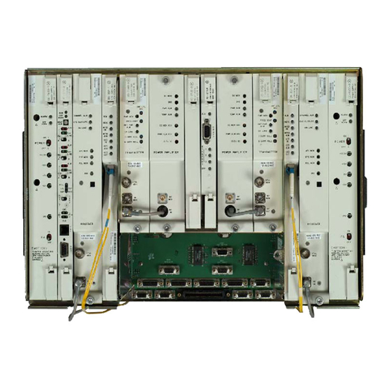
CommPak Indoor Shelf √ √ CommPak Outdoor Unit √ √ RELATED DOCUMENTATION The following documentation supplements the MDR-8000 Instruction Book and Must be ordered separately: Document Alcatel Part Number MDR-8000U CommLite Radio Instruction Book 3EM16680AAAA MDR-8000E Ethernet Radio Supplement 3EM17287AAAA... - Page 11 (DATA RATE) DS1/E1 LBO DS3 LBO DX- 35 P DX - 35N OC3 AUX INTFC LMW-7030-SM 06/09/04 D X- 35 M D S 1 /E I Figure 1-1 Typical MDR-8000 Hot-Standby Shelf Component Locations and Options (Sheet 1 of 3)
- Page 12 D S1 / E 1 SELECT DS1/E1 CAPACITY KEY BY CAPACITY AND MODULATION SCHEME LMW-9051-SM 2, 4, 8, 12, 16 DS1/E1 AND 32 OR 128 TCM. 02/15/04 Figure 1 - 1 Typical MDR-8000 Hot-Standby Shelf Component Locations and Options (Sheet 2 of 3)
- Page 13 Location of A and B RCV ports on diplexer filter varies, depending on RF frequency. For some frequencies, A and LMW-7211-SM B ports reverse location. 06/08/04 Figure 1-1 Typical MDR-8000 Hot-Standby Shelf Component Locations, and Options (Sheet 3 of 3 )
- Page 14 This page intentionally left blank.
-
Page 15: Operation
Until all radios in the transmission link are interconnected, turned on, and operating properly, alarm conditions may exist. Perform the following procedure to turn on the MDR-8000 series radios: On all power supply modules, set power ON/OFF switches to ON. -
Page 16: User System Interface (Usi) Provisioning Function/Operation
USER SYSTEM INTERFACE (USI) PROVISIONING FUNCTION/OPERATION The User System Interface (USI) software is used for maintenance and support of the radio including fault and status reporting. Refer to the Initial Turn-Up section for instruc- tions on loading and running the software. Refer to the User’s Guide section for descrip- tions and functions of the menus. - Page 17 NORM SHLF TOGGLE SWITCH LEFT TO SWITCH A XMTR, RCVR, OR I/O MODULE IN-SERVICE AND TOGGLE SWITCH RIGHT TO SWITCH B XMTR, RCVR, OR I/O MODULE IN-SERVICE. LINE LINE LINE NOTE OVERRIDE (OVRD) LOCKS XMTR, RCVR, OR I/O MODULE, SELECTED ABOVE IN-SERVICE, POLL REGARDLESS OF ALARMS.
- Page 18 1. OPEN USI CONTROLS SCREEN. Controls -- MDR-8000 DS3 File View Setup Options Alarm Status Analog Monitor Performance Station Alarm User Control Provisioning LOCAL CONTROLS ELMC Address: J7915 Communicating* Description: SILVERTON IN-SERVICE DS1 LINE LOOP-BACK RCV to XMT A Transmitter On Line Line 1 loopback 2.
-
Page 19: Radio Transmitter Manual Switching
Radio Transmitter Manual Switching 2.4.2 CAUTION Possibility of Service Interruption Switching the radio transmitter may momentarily interrupt traffic. Before switching the transmitter, obtain permission from the proper authority. Note When used in conjunction with a XMTR manual switch, press the OVRD switch to lock the XMTR on line regardless of alarms. - Page 20 Controls -- MDR-8000 DS3 File View Setup Options Alarm Status Analog Monitor Performance Station Alarm User Control Provisioning LOCAL CONTROLS ELMC Address: J7915 Communicating* Description: SILVERTON 1. SELECT XMTR TO PUT IN-SERVICE. IN-SERVICE SYSTEM LOOP-BACK DS1 LINE LOOP-BACK RCV to XMT 2.
-
Page 21: Mcs-11 Operation
An Operational Support System (OSS) provides a means to remotely monitor and control an MDR-8000 radio via an MCS-11 Monitor and Control System polling master. A Remote Station Summary (RSS), a Remote Detail Scanner (RDS), a Remote Analog Scanner (RAS), and a Remote Control Decoder (RCD) are available at the polling master for each radio network element. -
Page 22: Lamp Tests
Lamp Tests 2.4.5 Perform lamp tests by pressing and holding ACO/LT OVRD switch on controller front panel in ACO/LT position. All indicators on controller and indicators on all equipped modules should light. Release ACO/LT OVRD switch. Alarm Checks 2.4.6 The USI Alarm and Status screens provide alarms and status for the radio. Refer to description of alarms and status in the maintenance section. -
Page 23: Turn-Off Procedure
It is recom- mended that turn-off be performed only in an emergency. EMERGENCY OPERATION If an emergency occurs, such as a short circuit or a fire, turn off all MDR-8000 Microwave Digital Radio power supplies as quickly as possible. MODEM OPERATION Refer to the attached CD for modem connection and setup procedures. - Page 24 RED LED INDICATES MODULE FAULT OR REBOOT IN PROGRESS. 9-PIN D-TYPE CONNECTOR FOR INTERFACE WITH COMPUTER. DUAL-COLOR LED (GREEN/YELLOW) LIGHTS GREEN TO INDICATE LINK IS ACTIVE. BLINKS GREEN WHEN RE- CEIVING DATA PACKETS ON PORT. LIGHTS YELLOW TO INDICATE PORT IS MISCONFIGURED.
- Page 25 ETH 1 ETHERNET 1 RJ-45 CONNECTOR FOR UPLINK UPLINK CONNECTION TO ETHERNET HUB, SWITCH OR ROUTER ETH 2 ETHERNET 2 AND 3 RJ-45 CONNECTORS FOR NORMAL/BRIDGED CONNECTION TO OTHER SNMP PORTS OF OTHER NEs (RADIO, MUX, COMPUTERS) ETH 3 POINT-TO-POINT (PPP) RJ-45 CONNECTOR FOR CONNECTION TO OTHER RADIO TMN INTFC PPP PORTS.
- Page 26 YELLOW LED INDICATES ONE OR MORE RED LED INDICATES CONTROLLER FAILED. SOFTWARE OVERRIDES IN PROCESS OR FLASHING LED INDICATES INCORRECT ONE OR MORE SWITCHES ACTIVATED. FIRMWARE LOAD. RED LED INDICATES ANY MODULE IN SHELF FAILED. RED LED INDICATES XMTR A FAILED. RED LED INDICATES XMTR B FAILED.
- Page 27 ELMC OPTION KEY EPLD PROGRAMMING CONNECTOR (FACTORY TEST PURPOSES ONLY) LMW-7047 07/18/02 Figure 2-6 AE-37( ) Controller Controls, Indicators, and Connectors (Sheet 2 of 2) 2-13...
- Page 28 RED LED INDICATES INTERNAL FAILURE OR BLOWN FUSE. YELLOW LED INDICATES PA ON/OFF ALARM SWITCH IS SET TO OFF (LED IS LABELED OFF NORM ON OLDER VERSIONS OF PA OFF POWER SUPPLIES). ON 1 2-POSITION TOGGLE SWITCH APPLIES POWER TO POWER SUPPLY POWER (ON 1) OR REMOVES POWER (OFF 0).
- Page 29 SPARES 15A FAST BLO PN 264-0928-130 LMW-3160-sm 08/15/02 SIDE VIEW OF POWER SUPPLY Figure 2-7 CE-16BB Power Supply Controls, Indicators, Test Points, and Connectors (Sheet 2 of 2) 2-15...
- Page 30 RED LED INDICATES LOSS OF SIGNAL, DETECTION OF BIPOLAR VIOLATION, OR FAILURE OF ACTIVE DS1/E1 LINE(S). GREEN LED INDICATES I/O IN SERVICE. LINE SYNC RED LED INDICATES XMT SYNC FAILURE BETWEEN I/O INTERFACE MODULES. LINE COMMON LOSS RED LED INDICATES LOSS OF RCV FRAME SYNC. GREEN LED INDICATES RCVR IN SERVICE.
- Page 31 GREEN LED INDICATES AUXILIARY XMT CIRCUITS ARE ENABLED. ALLOWS TRANSFER OF DATA TO DS1/E1 INTFC CIRCUITS. RED LED INDICATES SERVICE CHANNEL FRAME LOSS DETECTED IN RCV CIRCUITS. GREEN LED INDICATES RCV CIRCUITS ARE ENABLED. ALLOWS TRANSFER OF DATA TO ENCODER/DECODER CIRCUITS. RCVR RED LED INDICATES RADIO LOSS OF FRAME DETECTED IN RCV CIRCUITS.
- Page 32 RED LED INDICATES MODULE FAILURE. GREEN LED INDICATES XMT AND/OR RCV CIRCUITS ARE PASSING DATA. INSVC GREEN LED INDICATES WAYSIDE DS1 IN SERVICE. WYSD WYSD YELLOW LED INDICATES WAYSIDE DS1 SIGNAL FAILURE. GREEN LED INDICATES OC3 DATA ON INPUT TO OPTICAL RCV/RADIO XMT CIRCUITS. YELLOW LED INDICATES OPTICAL RCV CIRCUIT FAILURE.
- Page 33 MONITORS RF ADJUSTS RF OUTPUT POWER XMT LVL OUTPUT AT OUTPUT OF XMTR (AND PA, IF EQUIPPED). DETECTED DC PWR MON ADJUSTS FUNDAMENTAL FREQ FREQ CONT XMT PWR OF CRYSTAL OSCILLATOR. ON LINE RED LED INDICATES XMTR POWER LOSS. I CARR NULL Q CARR NULL GREEN LED INDICATES XMTR IN SERVICE.
- Page 34 RED LED INDICATES LOSS OF LOCK FROM RECEIVE SIGNAL. YELLOW LED INDICATES DEGRADED RECEIVE SIGNAL. GREEN LED INDICATES RCVR IN SERVICE. CHAN ALM 2-POSITION TOGGLE SWITCH SETS AFC CLOSURE TO NORMAL (NORM) OR PEDESTAL (PED). ON LINE NORM POSITION LOCKS RCVR TO FAR-END XMTR.
- Page 35 RED LED INDICATES LOSS OF LOCK FROM RECEIVE SIGNAL. YELLOW LED INDICATES DEGRADED RECEIVE SIGNAL. CHAN ALM GREEN LED INDICATES RCVR IN SERVICE. CLOSURE ON LINE AFC MON EYE MON MONITOR POINT TO MEASURE DC CON- TROL VOLTAGE USED TO CONTROL LO RSL MON FREQ.
- Page 36 RED LED INDICATES LOSS OF RED LED INDICATES LOSS OF LOCK LOCK ON MAIN RECEIVE SIGNAL. ON DIVERSITY RECEIVE SIGNAL. YELLOW LED INDICATES YELLOW LED INDICATES DEGRADED DEGRADED MAIN RECEIVE SIGNAL. DIVERSITY RECEIVE SIGNAL. MN DV CHANNEL ALM GREEN LED INDICATES MAIN RCVR GREEN LED INDICATES DIVERSITY EYE CLOSURE IN SERVICE.
- Page 37 MONITOR POINT TO MEASURE DC VOLTAGE REPRESENTATIVE OF OUPUT POWER (0.1V DC PER DB OF RF OUTPUT SIGNAL FOR NOMINAL POWER ONLY) DC MON RED LED INDICATES RF PWR IS ABOVE OR BE- LOW ALARM THRESHOLD SET BY PWR ALM ADJ. PWR ALM YELLOW LED INDICATES HIGH TEMP ON PA TEMP ALM...
-
Page 38: Front View
FRONT VIEW FV/DC SWITCH SET TO FV FOR MDR-8000 APPLICATION NOT USED BIS BUTTON - PRESS NOT USED TO CALL LAST NUMBER DIALED ON-HOOK/OFF-HOOK SWITCH - PUSH FROM LEFT TO RIGHT TO TALK AND LISTEN REAR VIEW RJ11 CONNECTOR RJ11 CONNECTOR... -
Page 39: Interconnect
CD ROM. INSTALL POWER CABLE ASSEMBLIES See Figure 3 - 1 for power cable assembly installation procedures. The MDR-8000 is internally wired to accept 20.5 to 60 V dc input power with positive or negative ground. To protect main- tenance personnel from lightning strikes, the ground system must be integrated by bonding station ground and dc battery return together. - Page 40 Note Grounding of pole, antenna, customer interfaces, and all entrances to the building interior shall meet local electrical code and standard busi- ness practices. 1. DETERMINE IF INSTALLATION PIN 1 PIN 2 PIN 3 REQUIRES POS OR NEG GND. 2. INSTALL BATT, GND, AND JUMPER WIRES ON PWR CABLE ASSEMBLY.
-
Page 41: Pdu Strapping And Connections
PDU STRAPPING AND CONNECTIONS BATTERY INPUT WIRE SIZE NO. 4 (MAX) – – A BATT B BATT TOP VIEW POWER DISTRIBUTION PANEL FRONT VIEW – PANEL REMOVED 'A' BATTERY 'A' BATTERY 'B' BATTERY 'B' BATTERY -24/-48 +24/+48 -24/-48 +24/+48 STRAP E7 TO E15 FOR POSITIVE INPUT VOLTAGE. - Page 42 BATTERY INPUT WIRE SIZE NO. 4 (MAX) POWER DISTRIBUTION UNIT ISOMETRIC VIEW – CIRCUIT BOARD AND FRONT PANEL REMOVED A+ A- B+ B- BATTERY BATTERY BATTERY BATTERY FUSES FUSES FUSES FUSES CIRCUIT BOARD LOCATED INSIDE PDU JUMPER E39 TO E38 AND E42 TO E41 FOR POSITIVE RACK GND (AS SHOWN ABOVE).
-
Page 43: Shelf/Rack Alarm Connection
In order to activate a rack alarm visual indicator on the PDU, the shelf alarm output from each MDR-8000 shelf must be hardwired to connector J1 on the PDU. The shelf alarm is provided on alarm connector J305 pin 24 (major/visual alarm). - Page 44 AND SOCKET CONTACT: PN 372-0114-390 ABAM CABLE PN 424-0429-030 WIRE WRAP ADAPTER (PN 695-4171-002) PIN 1 MAJOR / VISUAL ALM J305 MDR-8000 SHELF FAN ASSY MAJOR / VISUAL ALM HEAT DEFLECTOR J305 MDR-8000 SHELF FAN ASSY LMW-7070-sm 07/24/02 Figure 3 - 3 Shelf Alarm Wiring PDU (695-6200-001/002) (Sheet 1 of 2)
- Page 45 OUTPUTS MAJOR 3 MINOR 3 MAJOR 4/AUX MINOR 4/AUX UNUSED FUSE ALM NC COM NO PIN 1 J305 MDR-8000 SHELF WIRE WRAP ADAPTER PIN 1 FAN ASSY HEAT DEFLECTOR J305 MDR-8000 SHELF FAN ASSY LMW-8057-SM 04/23/03 Figure 3-3 Shelf Alarm Wiring PDU (3EM13317AA) (Sheet 2 of 2)
-
Page 46: Ds1 Connections (J303 In And J304 Out)
DS1 CONNECTIONS (J303 IN AND J304 OUT) Recommended connectorized cable assembly – PN 695-7806-001 through -005 (22 AWG 16 pair shielded, jacketed cable with 37-pin D-type connector on one end). See Figure 3 - 4 for shelf con- nector location and pinout. Refer to Table 3 - 1 for mating cable wiring and color code. J303/J304 FRONT VIEW LMW-9037... - Page 47 Table 3-1 DS1 IN J303 and DS1 OUT J304 Pinout Assignments CONNECTOR PIN WIRE COLOR SIGNAL NAME CABLE PAIR NUMBER NUMBER WHITE–BLUE CHAN 1 TIP BLUE–WHITE CHAN 1 RING WHITE–ORANGE CHAN 2 TIP ORANGE–WHITE CHAN 2 RING WHITE–GREEN CHAN 3 TIP GREEN–WHITE CHAN 3 RING WHITE–BROWN...
-
Page 48: Ds1 Repeater (J314 On One Shelf To J314 On Second Shelf)
DS1 REPEATER (J314 ON ONE SHELF TO J314 ON SECOND SHELF) Note The DS1 repeater cable carries clocks, DS1 data, and overhead for two directions. If the 314 cable is not used, the embedded data in the over- head must be cabled individually. In this case, individual cables must be run for MCS–11, audio, RS-232, and ELMC. -
Page 49: Ds3 Lbo Strapping And Connections
DS3 LBO STRAPPING AND CONNECTIONS The DS3 LBO compensates for the distance to the cross-connect for DS3 and wayside DS1 outputs. See Figure 3 - 6 for strap locations. Refer to Table 3 - 2 for strapping requirements. IN/OUT STRAPPING IN/OUT STRAPPING WAYSIDE DS1 LINES DS3 LINES... -
Page 50: Ds3 Lbo Ds3 Bnc Connections (J21 Through J26)
DS3 LBO DS3 BNC CONNECTIONS (J21 THROUGH J26) BNC removal tool (PN 359-0092-010) is required for installing and removing BNC cables. Recommended connectorized cable assembly for all applications except repeaters, PN 632- 4429-096/180 (8/15 ft RG-59B/U coax cable with straight male BNC connector on one end and right angle male BNC connector on other end). -
Page 51: Ds3 Lbo Wayside Ds1 Connections (J201 In And J202 Out)
DS3 LBO WAYSIDE DS1 CONNECTIONS (J201 IN AND J202 OUT) Wayside DS1 is an option in the MDR-8000 DS3 radios. This option provides 1 DS1 for each equipped DS3. To activate the wayside channels requires a small circuit board, called ELMC option key, that plugs onto the controller module. -
Page 52: Wayside Ds1 Terminal
Wayside DS1 Terminal 3.9.1 Recommended connectorized cable assembly – PN 695-4125-041 (26 AWG 5 pair shielded, jacketed cable with 9-pin D-type connector on one end). See Figure 3 - 8 for shelf connector location and pinout. Refer to Interconnect section on attached CD for mating cable wiring and color code. -
Page 53: Wayside Ds1 Repeater
Wayside DS1 Repeater 3.9.2 Recommended connectorized cable assembly – PN 695-4125-051 (26 AWG 5 pair shielded, jacketed cable with 9-pin D-type connector on each end). See Figure 3 - 9 for Wayside DS1 repeater interconnect. SHELF 1 SHELF 2 OUTPUT J202 J202 OUTPUT... -
Page 54: Fiber Optic Cable Connections
J307 J308 J309 J310 J312 J315 J305 J313 J318 J316 J317 J302 LMW-7066-sm 07/23/02 J401 PIN 1 FRONT VIEW Figure 3 - 10 Connector J401 Location – DS3 LBO FIBER OPTIC CABLE CONNECTIONS 3.11 DANGER Possibility of Injury to Personnel This system normally operates as a Class I Laser Product (no hazard), however during servicing operations, when optical connectors are being connected, disconnected, or... -
Page 55: Or 4 Fiber Management Panel
Keep safety cap on connec- tors when not in use. The Alcatel 2 or 4 fiber management panel (PN 3EM09257AB) and 2x4 fiber management panel (PN 3EM09257AA) connections are described. For other fiber management equip- ment, refer to the manufacturers instructions. - Page 56 VIEW OF CONNECTOR WITH FIBER OPTIC CABLES REMOVED OT-1 OR-1 CONNECT OPTICAL RCV (OR) CABLE TO IN CONNECTOR CONNECT OPTICAL XMT (OT) CABLE TO OUT CONNECTOR LMW-6038 07/22/02 INPUTS OUTPUTS CUSTOMER INTFC SIDE VIEW I/O INTFC MODULE SIDE VIEW OT-3 OUT OT-1 OUT OT-2 OUT OT-4 OUT...
- Page 57 VIEW OF CONNECTOR WITH FIBER OPTIC CABLES OT-1 OR-1 REMOVED CONNECT OPTICAL RCV (OR) CABLE TO IN CONNECTOR CONNECT OPTICAL XMT (OT) CABLE TO OUT CONNECTOR FRONT VIEW COMBINER SPLITTER LMW-6037-sm 07/22/02 OT-1 OT-2 OR-1 OR-2 FROM RADIO I/O TO RADIO I/O INTFC MODULES INTFC MODULES OUTPUT TO...
-
Page 58: Oc3 Aux Interface Board Wayside Ds1 Connections (J201 In And J202 Out)
OC3 AUX INTERFACE BOARD WAYSIDE DS1 CONNECTIONS (J201 IN AND J202 OUT) 3.12 Wayside DS1 is an option in the MDR-8000 OC3 radios that prevents having to add a SONET add/drop MUX to access payload traffic. This option provides 1 DS1 for each STS-1 within the OC3. -
Page 59: Oc3 Repeater (J203 On One Shelf To J203 On Second Shelf)
OC3 REPEATER (J203 ON ONE SHELF TO J203 ON SECOND SHELF) 3.13 Note The OC3 radio repeater cable carries clocks, data, and overhead for two directions. It does not carry OC3 or Wayside DS1 traffic. OC3 fiber optic cables and Wayside DS1 cables must be run separately. If the repeater cable is not used, the embedded data in the overhead must be cabled individually. -
Page 60: Usi/Controller Cable Connection To Laptop (J301)
The MDR-8000 provides a 256 kb/s auxiliary channel for servicing the radio. This is an over- head channel and is independent of the traffic channels. The 256 kb/s service channel con- tains four 64 kb/s service channels. -
Page 61: Handset Jack
See Figure 3-16. There are eight connectors on the backplane to interface with three of the service channels. The connectors on the backplane interface three functions: audio, RS- 232, and MCS-11. Each service channel is provisioned for a specific function. As shown by the vertical line connecting to the three functions on one side and the three service chan- nels (SC1, SC2, and SC3) on the opposite side, audio and MCS can be put on any open ser- vice channel. -
Page 62: Service Channels Provisioning Options
Service Channels Provisioning Options 3.15.2 Note Service channels at both ends of a hop (and end-to-end in a link) must be provisioned the same. Service channel provisioning is interactive. When an option is selected for any service channel, that option is excluded from selections on the other applicable service channels. Provisioning options for Service Channels 1, 2, and 3 are listed: •... - Page 63 Audio 1 Audio 1 (J316) is a 4-wire function port on the backplane that provides off-hook detection, level control, E and M-lead signaling, DTMF, and 2-wire handset capabilities. Audio 2 Audio 2 (J317) is a 4-wire function port on the backplane that provides off-hook detection, level control, and E and M-lead signaling.
- Page 64 Table 3 - 6 Audio Mating Cable Wiring and Color Codes FUNCTION END 1 WIRE COLOR PAIR WIRE COLOR END 2 FUNCTION AUDIO TIP IN BLACK BLACK AUDIO TIP OUT AUDIO RING IN AUDIO RING OUT AUDIO M LEAD BLACK BLACK AUDIO E LEAD AUDIO E LEAD...
-
Page 65: Rs-232-1, Rs-232-2 (J312, J313)
RS-232-1, RS-232-2 (J312, J313) 3.15.4 Recommended connectorized cable assembly – PN 695-4125-021 through 025 (26 AWG 5 pair shielded, jacketed cable with 9-pin D-type connector on each end). See Figure 3 - 19 for shelf connector locations and pinout. Refer to Table 3 - 7 for mating cable wiring and color code. J307 J308 J308... -
Page 66: Mcs-11 Connections
Table 3 - 7 RS-232 Mating Cable Wiring and Color Codes J312/J313 MDR-8000 J312/J313 J312/J313 MDR-8000 FUNCTION END 1 WIRE COLOR PAIR WIRE COLOR END 2 FUNCTION NOT USED BLACK BLACK NOT USED NOT USED NOT USED RS-232 OUT/ BLACK... - Page 67 MCS-11 (J307) 3.15.5.1 Note If the radio is provisioned , port 2 on the controller, that con- Repeater nects to J307, is disabled. At a repeater, you can use J310 in lieu of J307 for connecting the TSM polling engine to the radio. MCS-11 connector J307 is used to connect to a TSM (-2500, -3500, or -8000) polling engine at a master terminal.
- Page 68 Table 3 - 8 MCS-11 Master Connector J307 Mating Cable Wiring and Color Codes J307 MDR-8000 POLLING ENGINE FUNCTION END 1 WIRE COLOR PAIR WIRE COLOR END 2 FUNCTION RCV CLK + BLACK BLACK RCV CLK + RCV CLK- RCV CLK-...
- Page 69 CABLE 372-0546-020/050/070 TERM RPTR J314 S7341 T7341 MDR-6000 MDR-6000 SITE A LEGEND: MDR-8000 J308/J309 XXXX MCS-11 ADDRESS PROVISIONING NOTES YYYY CONFIGURATION 1. PROVISION RPTR DS309 (FIRST RADIO IN CHAIN) J308 OUTPUT CLOCK ZZZZ ELMC ADDRESS DS3ZZ = RADIO CAPACITY (DS3) 2.
- Page 70 MCS-11 Repeater-to-Spur Daisy Chain Connection (J308/J309) 3.15.5.2 Note MCS-11 must be provisioned MCS-11 J310 Master/Junction to enable XMT, RCV, and OUTPUT clocks. If an external modem is being used, provision MCS-11 for . This selection disables MCS-11 J310 Modem XMT, RCV,OUTPUT clocks and all MCS-11 clocks must now be pro- vided by the external modem.
- Page 71 J307 J308 J308 J309 J310 J312 J312 J315 J305 J313 J318 J316 J317 J302 MDR-1012 04/12/04 OFF HOOK + OFF HOOK + XMT DATA + XMT DATA + CLK OUT + XMT CLK + XMT CLK + RCV DATA + RCV DATA + RCV CLK + RCV CLK +...
- Page 72 Table 3 - 9 J308-to-J308 Mating Cable Wiring and Pinout J308 MDR-8000 J308/J308 J308 MDR-8000 FUNCTION END 1 WIRE COLOR PAIR WIRE COLOR END 2 FUNCTION RCV CLK + BLACK BLACK XMT CLK + RCV CLK- XMT CLK- RCV DATA +...
- Page 73 MCS-11 Spur Connection (J310) 3.15.5.3 MCS-11 connector J310 can be used to connect to a spur shelf and is the preferred connec- tion to the external DMX-3003N MUX. When connecting to a MDR-4000e or MDR-6000 radio use J310 on all of the radios for best results. Recommended connectorized cable assembly –...
-
Page 74: Elmc (J315, J318)
Table 3 - 11 MCS-11 Spur Connector J310 Mating Cable Wiring and Pinout J310 MDR-8000 J310/J310 J310 MDR-8000 FUNCTION END 1 WIRE COLOR PAIR WIRE COLOR END 2 FUNCTION RCV CLK + BLACK BLACK RETURN CLK + RCV CLK- RETURN CLK-... - Page 75 ELMC 1 connector J318 and ELMC 2 connector J315 are wired in par- allel. You can connect J315 to J315, J315 to J318, or J318 to J318. A typical connection scheme is shown. Table 3-13 ELMC Connector J315/J318 Mating Cable Wiring and Pinout J315/J318 MDR-8000 J315/J318 MDR-8000 FUNCTION END 1...
- Page 76 J307 J308 J308 J309 J309 J310 J312 J312 J315 J315 J305 J313 J313 J318 J318 J316 J317 J302 LMW-7237 02/23/04 XMT + J315/J318 RCV + RCV – XMT – FRONT VIEW Figure 3 - 24 ELMC Connectors Location and Pinout 3-38...
- Page 77 MDR-6000 Note When connecting MDR-8000 radios with Windows USI to radios with DOS USI, check the DOS USI ELMC address for space, dash, slash, asterisk, or underscore. The Windows USI cannot recognize a space, dash, slash, asterisk, or underscore. Change the DOS ELMC address to a 5-character alphanumeric address without the prohibited characters.
-
Page 78: Foreign Alarm Interface (J305)
FOREIGN ALARM INTERFACE (J305) 3.16 Recommended connectorized cable assembly – PN 695-4121-001/003 (24 AWG 25 pair cable). See Figure 3 - 26 for shelf connector location and pinout. Refer to Table 3 - 13 for mating cable pinout and color code. Recommended wirewrap cable –... - Page 79 Table 3-14 Alarm/Status Connector J305 Mating Cable Wiring and Pinout WIRE ALM/STATUS/CONTROL REMARKS COLOR A XMT ALM OUT WHT/BLU ALARM OUTPUT FROM RELAY INTFC B XMT ALM OUT BLU/WHT ALARM OUTPUT FROM RELAY INTFC A RCV ALM OUT WHT/ORN ALARM OUTPUT FROM RELAY INTFC B RCV ALM OUT ORN/WHT ALARM OUTPUT FROM RELAY INTFC...
- Page 80 Table 3 - 14 (Cont.) Alarm/Status Connector J305 Mating Cable Wiring and Pinout WIRE ALM/STATUS/CONTROL REMARKS COLOR TBOS XMT+ DATA IN OR STA- BLK/BRN SERIAL DATA INPUT TO RADIO CON- TION ALM 14 IN TROLLER OR RELAY INPUT FROM CUS- TOMER EQUIPMENT TO RELAY INTFC CARD (PROVISIONABLE) STATION ALM 6 IN...
-
Page 81: Alarm, Status, Controls Interconnect
ALARM, STATUS, CONTROLS INTERCONNECT 3.17 See Figure 3 - 27 for interconnect diagram. The AE-27( ) Relay Interface provides alarm, control and status inputs, and alarm, status and control relay outputs. All output relays can be disabled or provisioned normally open or normally closed as follows: Normally open (NO) –... - Page 82 J305 RELAY J305 SWITCH XMTR INTERFACE SWITCH RCVR PATH ALM SWITCH I/O LOSS OF INPUT ALM A XMT ALM STATION ALM 1 STATION ALM 2 B XMT ALM STATION ALM 3 A RCV ALM STATION ALM 4 B RCV ALM STATION ALM 5 STATION ALM 6 POWER SUPPLY ALM...
-
Page 83: Controller Bus
Controller Bus 3.17.1 The Relay Interface communicates with the AE-37( ) Controller card via the processor bus and the data bus. The processor bus, consisting of three address lines, two control lines, and a clock, is applied to a XCVR. The data bus contains the eight data lines (D0-D7) and is applied to a separate transceiver. -
Page 84: Station Alarm Wiring
1) is connected by software. The station alarms for MCS-11 address A1B and A1C are assigned to MCS-11 Alarm points 2 and 3, respectively. WIRE WRAP ADAPTER (PN 695-4171-002) #1 STATION PIN 1 (SEE NOTE) RACK ALM J305 MDR-8000 SHELF MCS-11 ADDRESS #2 STATION FAN ASSY HEAT DEFLECTOR J305 MDR-8000 SHELF MCS-11... -
Page 85: Relay Alarm/Status Outputs
Relay Alarm/Status Outputs 3.17.5 Eight alarm relay outputs and seven status relay outputs provide relay closure to ground (provisioned NO) or open (provisioned NC) when activated. All relays default to open if card power is lost, except the Power Supply alarms, which default to ground. The maxi- mum contact rating for each relay is 0.5 A, 100 Vdc. - Page 86 • B RCV – B-side receiver failure. This summary alarm is activated by any of the fol- lowing alarms on the B side: Channel Alarm RCV Frame Loss Eye Closure RSL Alarm • PWR Supply Alarm – This summary alarm is activated by any A or B power supply failure.
-
Page 87: Relay Control Outputs
Relay Control Outputs 3.17.6 Note Control outputs and control status inputs operate together to perform control functions. The control status inputs to the relay interface must be properly wired to the external equipment that is being controlled by the associated control output in order to display the ON or OFF status on the USI control screen. - Page 88 3-50 This page intentionally left blank.
-
Page 89: Initial Turnup
This provisioning part of the section describes provisioning options available with the MDR-8000 software application. Provisioning allows for the definition, editing, and storing of specific functions. The MDR-8000 provides the ability to provision equipment and facili- ties through a series of Windows™-based screens and messages. The Provisioning menu lists equipment and functions which may be provisioned. -
Page 90: Test Procedures
The MDR-8000 application software offers user password security management using two different levels of passwords. User security deals with access level assigned to specific users. The level of user security affects the type and number of commands an individual user may execute. This prevents an unqualified user’s access to high-level commands. - Page 91 START FIG 4-2 DS1/E1, DS3, OC3/STM-1 RADIO CONFIG PROVISIONING DS1/E1 FIG 4-3 FIG 4-5 FIG 4-8 DS1/E1 RADIO DS3 RADIO OC3/STM-1 RADIO CONFIG CONFIG CONFIG PROVISIONING PROVISIONING PROVISIONING FIG 4-4 FIG 4-6 FIG 4-9 DS1/E1 OC3/STM-1 FACILITIES FACILITIES FACILITIES PROVISIONING PROVISIONING PROVISIONING FIG 4-7...
- Page 92 CHANNEL (FOUR RAILS OF X/Y DATA) ARE BEING TRANSPORTED BETWEEN J314 OF BOTH SHELVES. SYSTEM ID: ELMC: RADIO LINK ID: R112 Disable RADIO TYPE: MDR-8000 OC3 OC-3 128 TCM 10-11 GHz RADIO CONFIG: Hot-Standby Tx Hot-Standby Rx TERMINAL ATPC Disable...
- Page 93 HOUR, ATPC GOES HIGH FOR 10 SECONDS AND THEN GOES TO LOW POWER. THIS CONTINUES UNTIL THE CMD PATH IS RESTORED. SELECT DISABLE TO DISABLE ATPC FUNCTION. SYSTEM ID: ELMC: TEST1 RADIO LINK ID: Disable RADIO TYPE: MDR-8000 DS1 16 LINES 128 TCM 6-8 GHz RADIO CONFIG: HS Tx/HS Rx TERMINAL ATPC Enabled A&B PA Present...
- Page 94 CHANNELS. THE FAILURE IS WHAT NOW BREAKS THE SERVICE CHANNEL LOOP, PREVENTING THE RING FROM CLOSING ON ITSELF. SYSTEM ID: ELMC: TEST1 RADIO LINK ID: Disable RADIO TYPE: MDR-8000 DS1 16 LINES 128 TCM 6-8 GHz RADIO CONFIG: HS Tx/HS Rx Ring Repeater TERMINAL...
- Page 95 RING TERMINAL MASTER – NOT USED SYSTEM ID: ELMC: RADIO LINK ID: Disable TEST1 RADIO TYPE: MDR-8000 OC3 OC-3 128 QAM RADIO CONFIG: HS Tx HS Rx Ring Repeater Normal Terminal Normal ATPC Enabled A&B PA Present Repeater Primary Ring Terminal...
- Page 96 Radio Configuration Service Channel DS1 Facilities ELMC: DS105 RADIO LINK ID: Disable SYSTEM ID: MDR-8000 DS1 16 LINES 128 TCM RADIO TYPE: 6GHz RADIO CONFIG: Non-Standby Tx Hot-Standby Rx TERMINAL ATPC Enabled A&B PA Present Relay Card Present SYSTEM ALARM:...
- Page 97 Radio Configuration Service Channel DS1 Facilities ELMC: DS105 RADIO LINK ID: Disable SYSTEM ID: RADIO TYPE: MDR-8000 DS1 16 LINES 128 TCM 6GHz RADIO CONFIG: Non-Standby Tx Non-Standby Tx Non-Standby Rx Non-Standby Rx TERMINAL ATPC Enabled A&B PA Present Relay Card Present...
- Page 98 Radio Configuration Service Channel DS1 Facilities ELMC: DS105 RADIO LINK ID: Disable SYSTEM ID: MDR-8000 DS1 16 LINES 128 TCM RADIO TYPE: U6-8GHz RADIO CONFIG: Non-Standby Tx Non-Standby Tx Hot-Standby Rx Hot-Standby Rx Repeater ATPC Disable A&B PA Present Relay Card Present...
- Page 99 Radio Configuration Service Channel DS1 Facilities ELMC: DS105 RADIO LINK ID: Disable SYSTEM ID: RADIO TYPE: MDR-8000 DS1 16 LINES 128 TCM U6-8GHz RADIO CONFIG: Non-Standby Tx Non-Standby Tx Space Diversity Rx Space Diversity Rx Repeater ATPC Disable A&B PA Present...
- Page 100 Radio Configuration Service Channel DS3 Facilities ELMC: DS105 RADIO LINK ID: Disable SYSTEM ID: MDR-8000 DS1 16 LINES 128 TCM RADIO TYPE: U6-8GHz RADIO CONFIG: Hot-Standby Tx Hot-Standby Tx Hot-Standby Rx Hot-Standby Rx Repeater ATPC Disable A&B PA Present Relay Card Present...
- Page 101 Radio Configuration Service Channel DS1 Facilities ELMC: DS105 RADIO LINK ID: Disable SYSTEM ID: RADIO TYPE: MDR-8000 DS1 16 LINES 128 TCM U6-8GHz RADIO CONFIG: Hot-Standby Tx Hot-Standby Tx Space Diversity Rx Space Diversity Rx Repeater ATPC Disable A&B PA Present...
- Page 102 Radio Configuration Service Channel DS1 Facilities ELMC: DS105 RADIO LINK ID: Disable SYSTEM ID: MDR-8000 DS1 16 LINES 128 TCM RADIO TYPE: U6-8GHz RADIO CONFIG: Freq-Diversity Tx Freq-Diversity Tx Freq-Diversity Rx Freq-Diversity Rx Repeater ATPC Disable A&B PA Present Relay Card Present...
- Page 103 Note If installation at both ends of a hop are complete except for connecting to customer inputs/outputs and it is desirable to have an alarm-free system, alarm reporting on the incomplete connections can be disabled temporarily through provisioning. You can communicate over the hop even if you do not have the radio connected to customer DS1 inputs;...
- Page 104 Radio Configuration Service Channel DS3 Facilities WaySide DS1 Facilities ELMC: DS305 RADIO LINK ID: Disable SYSTEM ID: MDR-8000 DS3 3 LINES 64 QAM RADIO TYPE: 6GHz RADIO CONFIG: Non-Standby Tx Hot-Standby Rx TERMINAL ATPC Enabled A&B PA Present Relay Card Present...
- Page 105 Radio Configuration Service Channel DS3 Facilities WaySide DS1 Facilities ELMC: DS305 RADIO LINK ID: Disable SYSTEM ID: RADIO TYPE: MDR-8000 DS3 3 LINES 64 QAM U6-8GHz RADIO CONFIG: Non-Standby Tx Non-Standby Tx Non-Standby Rx Non-Standby Rx Repeater ATPC Disable A&B PA Present...
- Page 106 Radio Configuration Service Channel DS3 Facilities WaySide DS1 Facilities ELMC: DS305 RADIO LINK ID: Disable SYSTEM ID: MDR-8000 DS3 3 LINES 64 QAM RADIO TYPE: U6-8GHz RADIO CONFIG: Non-Standby Tx Non-Standby Tx Hot-Standby Rx Hot-Standby Rx Repeater ATPC Disable A&B PA Present...
- Page 107 Radio Configuration Service Channel DS3 Facilities WaySide DS1 Facilities ELMC: DS305 RADIO LINK ID: Disable SYSTEM ID: RADIO TYPE: MDR-8000 DS3 3 LINES 64 QAM U6-8GHz RADIO CONFIG: Non-Standby Tx Non-Standby Tx Space Diversity Rx Space Diversity Rx Repeater ATPC Disable A&B PA Present...
- Page 108 Radio Configuration Service Channel DS3 Facilities WaySide DS1 Facilities ELMC: DS305 RADIO LINK ID: Disable SYSTEM ID: MDR-8000 DS3 3 LINES 64 QAM RADIO TYPE: U6-8GHz RADIO CONFIG: Non-Standby Tx Non-Standby Tx Space Diversity Rx Space Diversity Rx Repeater ATPC Disable A&B PA Present...
- Page 109 Radio Configuration Service Channel DS3 Facilities WaySide DS1 Facilities ELMC: DS305 RADIO LINK ID: Disable SYSTEM ID: MDR-8000 DS3 3 LINES 64 QAM RADIO TYPE: U6-8GHz RADIO CONFIG: Hot-Standby Tx Hot-Standby Tx Hot-Standby Rx Hot-Standby Rx Repeater ATPC Disable A&B PA Present...
- Page 110 Radio Configuration Service Channel DS1 Facilities ELMC: DS105 RADIO LINK ID: Disable SYSTEM ID: RADIO TYPE: MDR-8000 DS1 16 LINES 128 TCM U6-8GHz RADIO CONFIG: Hot-Standby Tx Hot-Standby Tx Space Diversity Rx Space Diversity Rx Repeater ATPC Disable A&B PA Present...
- Page 111 Radio Configuration Service Channel DS3 Facilities WaySide DS1 Facilities ELMC: DS305 RADIO LINK ID: Disable SYSTEM ID: MDR-8000 DS3 3 LINES 64 QAM RADIO TYPE: U6-8GHz RADIO CONFIG: Freq-Diversity Tx Freq-Diversity Tx Freq-Diversity Rx Freq-Diversity Rx Repeater ATPC Disable A&B PA Present...
- Page 112 Radio Configuration Service Channel DS3 Facilities WaySide DS1 Facilities ELMC: DS305 RADIO LINK ID: Disable SYSTEM ID: RADIO TYPE: MDR-8000 DS3 3 LINES 64 QAM U6-8GHz RADIO CONFIG: Freq-Diversity Tx Freq-Diversity Tx Freq-Diversity Rx Freq-Diversity Rx Repeater ATPC Disable A&B PA Present...
- Page 113 Radio Configuration Service Channel DS3 Facilities WaySide DS1 Facilities ELMC: DS305 RADIO LINK ID: Disable SYSTEM ID: MDR-8000 DS3 3 LINES 64 QAM U6-8GHz RADIO TYPE: RADIO CONFIG: Hot Standby Tx Hot Standby Tx Non Standby Rx Non Standby Rx...
- Page 114 Radio Configuration Service Channel DS3 Facilities WaySide DS1 Facilities ELMC: DS305 RADIO LINK ID: Disable SYSTEM ID: MDR-8000 DS3 3 LINES 64 QAM RADIO TYPE: U6-8GHz RADIO CONFIG: Hot Standby Tx Simplex Ns Tx Non Standby Rx None Repeater ATPC Disable A&B PA Present...
- Page 115 Radio Configuration Service Channel DS3 Facilities WaySide DS1 Facilities ELMC: DS305 RADIO LINK ID: Disable SYSTEM ID: RADIO TYPE: MDR-8000 DS3 3 LINES 64 QAM U6-8GHz RADIO CONFIG: Simplex Hs Tx Simplex Hs Tx None None Repeater ATPC Disable A&B PA Present...
- Page 116 Radio Configuration Service Channel DS3 Facilities WaySide DS1 Facilities ELMC: DS305 RADIO LINK ID: Disable SYSTEM ID: MDR-8000 DS3 3 LINES 64 QAM RADIO TYPE: U6-8GHz RADIO CONFIG: None None Simplex Ns Rx Simplex Ns Rx Repeater ATPC Disable A&B PA Present...
- Page 117 Radio Configuration Service Channel DS3 Facilities WaySide DS1 Facilities ELMC: DS305 RADIO LINK ID: Disable SYSTEM ID: MDR-8000 DS3 3 LINES 64 QAM RADIO TYPE: U6-8GHz RADIO CONFIG: None None Simplex SD Rx Simplex SD Rx Repeater ATPC Disable A&B PA Present...
- Page 118 Note If installation at both ends of a hop are complete except for connecting to customer inputs/outputs and it is desirable to have an alarm-free system, alarm reporting on the incomplete connections can be disabled temporarily through provisioning. You can communicate over the hop even if you do not have the radio connected to customer DS3 and wayside DS1 inputs;...
- Page 119 SELECT AMI OR B8ZS CODING FOR WAYSIDE DS1 LINE. SELECT ON TO DISABLE ALARM REPORTING FOR WAYSIDE DS1 LINE. SELECT OFF TO REPORT ALL ALARMS FOR THAT LINE. DS1 CARD A DS1 CARD B DS1 LINES Select All ALARM LOCK OUT DS1 LINE CODING AIS INHIBIT AIS INSERT...
- Page 120 SYSTEM ID: ELMC: TEST 1 RADIO LINK ID: Disable RADIO TYPE: MDR-8000 OC3 OC3-3 128 TCM RADIO CONFIG: HS Tx TERMINAL HS Rx ATPC Enabled A&B PA Present SYSTEM ALARM Visual/Audible RELAYS ON/NO Station Alarm 13-16 RSL Alarm Enable RCV SWITCHING:...
- Page 121 TION IN APPLICATIONS WHERE FRAME AND PARITY INSERT IS PERFORMED EXTERNALLY. SELECT Frame TO INSERT SECTION OVERHEAD DATA. SELECT Frame & B1 TO INSERT SECTION OVERHEAD DATA AND PARITY BIT. Alcatel User Interface – [Provisioning] File View Setup Options Prov. Save...
- Page 122 Fiber Configuration 2 Fiber 2 Fiber 2 Fiber Frame & B1 Section OH Insertion 2 Fiber Switched 4 Fiber MDR-8000 OC3 Controller Version R1.00 Tuessday, March 7, 2000 1:27:15 PM USI Version R1.00 4 Fiber Switched TRANSMITTER RECEIVER Select All...
- Page 123 Fiber Configuration 2 Fiber 2 Fiber 2 Fiber Frame & B1 Section OH Insertion 2 Fiber Switched 4 Fiber MDR-8000 OC3 Controller Version R1.00 Tuessday, March 7, 2000 1:27:15 PM USI Version R1.00 4 Fiber Switched TRANSMITTER RECEIVER Select All...
- Page 124 Fiber Configuration 2 Fiber Switched 2 Fiber 2 Fiber Frame & B1 Section OH Insertion 2 Fiber Switched 4 Fiber MDR-8000 OC3 Controller Version R1.00 Tuessday, March 7, 2000 1:27:15 PM USI Version R1.00 4 Fiber Switched TRANSMITTER RECEIVER Select All...
- Page 125 OC3 Facilities Fiber Configuration 4 Fiber Switched 2 Fiber Frame & B1 Section OH Insertion 2 Fiber Switched 4 Fiber MDR-8000 OC3 Controller Version R1.00 Tuessday, March 7, 2000 1:27:15 PM USI Version R1.00 4 Fiber Switched TRANSMITTER RECEIVER Select All...
- Page 126 2 Fiber Fiber Configuration 2 Fiber 2 Fiber Frame & B1 Section OH Insertion 2 Fiber Switched 4 Fiber MDR-8000 OC3 Controller Version R1.00 Tuessday, March 7, 2000 1:27:15 PM USI Version R1.00 4 Fiber Switched TRANSMITTER RECEIVER Select All...
- Page 127 2 Fiber Switched 2 Fiber Frame & B1 Section OH Insertion 2 Fiber Switched 2 Fiber Switched 4 Fiber MDR-8000 OC3 Controller Version R1.00 Tuessday, March 7, 2000 1:27:15 PM USI Version R1.00 4 Fiber Switched TRANSMITTER RECEIVER Select All...
- Page 128 Fiber Configuration 4 Fiber Switched 2 Fiber Frame & B1 Section OH Insertion 2 Fiber Switched 4 Fiber MDR-8000 OC3 Controller Version R1.00 Tuessday, March 7, 2000 1:27:15 PM USI Version R1.00 4 Fiber Switched 4 Fiber Switched TRANSMITTER RECEIVER...
- Page 129 Fiber Configuration 2 Fiber 2 Fiber 2 Fiber Frame & B1 Section OH Insertion 2 Fiber Switched 4 Fiber MDR-8000 OC3 Controller Version R1.00 Tuessday, March 7, 2000 1:27:15 PM USI Version R1.00 4 Fiber Switched TRANSMITTER RECEIVER Select All...
- Page 130 2 Fiber Switched 2 Fiber Frame & B1 Section OH Insertion 2 Fiber Switched 2 Fiber Switched 4 Fiber MDR-8000 OC3 Controller Version R1.00 Tuessday, March 7, 2000 1:27:15 PM USI Version R1.00 4 Fiber Switched TRANSMITTER RECEIVER Select All...
- Page 131 OC3 Facilities Fiber Configuration 4 Fiber Switched 2 Fiber Frame & B1 Section OH Insertion 2 Fiber Switched 4 Fiber MDR-8000 OC3 Controller Version R1.00 Tuessday, March 7, 2000 1:27:15 PM USI Version R1.00 4 Fiber Switched TRANSMITTER RECEIVER Select All...
- Page 132 2 Fiber Switched 2 Fiber Frame & B1 Section OH Insertion 2 Fiber Switched 2 Fiber Switched 4 Fiber MDR-8000 OC3 Controller Version R1.00 Tuessday, March 7, 2000 1:27:15 PM USI Version R1.00 4 Fiber Switched TRANSMITTER RECEIVER Select All...
- Page 133 OC3 Facilities Fiber Configuration 4 Fiber Switched 2 Fiber Frame & B1 Section OH Insertion 2 Fiber Switched 4 Fiber MDR-8000 OC3 Controller Version R1.00 Tuessday, March 7, 2000 1:27:15 PM USI Version R1.00 4 Fiber Switched TRANSMITTER RECEIVER Select All...
- Page 134 OC3 Facilities Fiber Configuration 4 Fiber Switched 2 Fiber Frame & B1 Section OH Insertion 2 Fiber Switched 4 Fiber MDR-8000 OC3 Controller Version R1.00 Tuessday, March 7, 2000 1:27:15 PM USI Version R1.00 4 Fiber Switched TRANSMITTER RECEIVER Select All...
- Page 135 Figure 4-10 OC3/STM-1 Radio Wayside DS1 Facilities Provisioning Note A password is not required to operate the MDR-8000. The radio is shipped without a password and if a password is desired, it must be entered using the Change Password screen. Once entered initially, the...
- Page 136 Change Password -- Change Level 1 Password Enter the New Level 1 Password: Confirm the New Level 1 Password: Change Level 2 Password Enter the New Level 2 Password: Confirm the New Level 2 Password: Cancel Save Password Forgot Password MDR-1033 09/02/04 Level One Password --...
- Page 137 Alcatel User Interface – [System, DS3, and DS1 Provisioning -- MDR-8000 DS3] File View Setup Options Prov. Save Alarm Status Analog Monitor Performance Station Alarm User Control Provisioning LOCAL DS3 PROVISIONING ELMC Address: J7914 ELMC Description: DURANGO Communicating*** Radio Configuration...
- Page 138 Alcatel User Interface – [System, DS3, and DS1 Provisioning -- MDR-8000 DS3] port 1 J316 or audio port 2 J317 on the radio backplane. These provisionable 4-wire File View Setup Options audio functions should not be confused with the 2-wire audio handset.
- Page 139 HANDSET IS PARTY-LINE. DTMF ADDRESSING IS A LOCAL FUNCTION NOT A NETWORK FUNCTION, THEREFORE, IF ONE OR MORE RADIOS ARE ASSIGNED THE SAME DTMF ADDRESS, THEY WILL ALL RING WHEN THAT ADDRESS IS Alcatel User Interface – [System, DS3, and DS1 Provisioning -- MDR-8000 DS3] DIALED. File View Setup Options TO BE ABLE TO USE THE DTMF FUNCTION: 1.
- Page 140 Alcatel User Interface – [System, DS3, and DS1 Provisioning -- MDR-8000 DS3] File View Setup Options Prov. Save Alarm Status Analog Monitor Performance Station Alarm User Control Provisioning LOCAL DS3 PROVISIONING ELMC Address: J7914 ELMC Description: DURANGO Communicating*** Radio Configuration...
- Page 141 Channel 1 Channel 2 Repeater D/1 RS-232 SELECT FOR TERMINAL (ONE DIRECTION) AE-37( ) CONTROLLER SC MULDEM J343 J314 RCV SC DATA E TO/FROM DROP XMT SC I/O INTFC DATA W INSERT RS-232 RXD1 RS-232 TXD1 J312 DATA PATH NOT USED Channel 1 Channel 2 Repeater D/1...
- Page 142 Note MCS-11 is enabled by selecting TMN . This places Channel 1, 2, the alarm control/status data on service channel 1, 2, or 3. If you are using the TSM-2500 or TSM-8000 to manage the MCS-11 data, service channel 1, 2, or 3 must be selected in order to transport the MCS-11 data over the service channel.
- Page 143 MCS-11 MCS-11 Port Port MCS-11 MCS-11 + PPP MDR-8000 MDR-8000 RPTR RPTR Port Port PPP Transport – None PPP Transport – RPTR MCS-11 + PPP MCS-11 + PPP Port Port MCS-11 MCS-11 + PPP MDR-8000 MDR-8000 RPTR RPTR Port Port PPP Transport –...
- Page 144 Alcatel User Interface – [System, DS3, and DS1 Provisioning -- MDR-8000 DS3] File View Setup Options Prov. Save Alarm Status Analog Monitor Performance Station Alarm User Control Provisioning Note LOCAL DS3 PROVISIONING ELMC Address: J7914 A default MCS-11 address is assigned automatically.
- Page 145 7. CLICK HERE DESCRIPTION ELMC ADDRESS. EXACTLY. TO ENTER NEW (IF DESIRED). 4. OPEN ELMC ADDRESS ADDRESS AND SETUP SCREEN. DESCRIPTION Setup ELMC Address -- MDR-8000 Extended Link Monitor Channel (Elmc) Address J7914 DURANGO ELMC: J7914 Description: DURANGO Add Elmc=> Save...
- Page 146 Current time-out is 3 secs 4 secs 5 secs 6 secs 7 secs 8 secs 9 secs 10 secs Cancel Alcatel User Interface - [Alarm Status -- MDR-8000 OC3] File View Setup Options ✓ Acknowledge Alarm Status Analog Monitor Station Alarm User Control Provisioning...
- Page 147 NOTE: DEFAULT CONTROL NAMES ARE USER CONTROL 1-6 1. OPEN USER CONTROL NAMES SETUP SCREEN 2. SELECT RADIO User Control Names Setup -- MDR-8000 CONTROL NAMES ELMC List GEN START RACK1 DURANGO RACK2 DURANGO TWR LIGHT OVRD RACK3 RED MTH PASS...
- Page 148 1. SELECT RADIO CLICK HERE TO SAVE Alcatel User Interface – [Provisioning MDR-8000 OC3] File View Setup Options Prov. Save Alarm Status Analog Monitor Performance Station Alarm User Control Password ELMC ADDRESS: S302 LOCAL DS3 PROVISIONING Communicating*** ELMC ADDRESS: DS301 -- MDR-8000 DS3...
-
Page 149: Maintenance
RECOMMENDED TEST EQUIPMENT Refer to Table 5 - 1 for the list of recommended test equipment. Alcatel recommends this test equipment to properly maintain the radio. Table 5 - 1 Recommended Test Equipment... -
Page 150: Optional Test Equipment
OPTIONAL TEST EQUIPMENT Refer to Table 5 - 2 for a list of optional test equipment to support alternate test procedures in this section and the over-the-hop test procedure in Appendix E on the attached CD. Table 5 - 2 Optional Equipment Essential Test Equipment/Function Used On... -
Page 151: Recommended Periodic Checks
RECOMMENDED PERIODIC CHECKS Perform XMT local oscillator frequency verification (Para. 5.14) and XMTR Output Check (Para. 5.15) one year after initial setting and at 5-year intervals thereafter to correct for possible drift caused by aging. TROUBLESHOOTING The digital radio system is equipped with alarm circuitry and automatic switching (in hot- standby, frequency diversity, and space diversity configurations) to provide protection against loss of traffic. -
Page 152: Troubleshooting Using The Usi Rsl Screens
Troubleshooting Burst Errors 5.5.2.1 Burst errors are defined as multiple errors in a very short time. Burst errors can be caused by many things, including loose connections on cable or waveguide at either end of the hop. A “popping” oscillator can cause burst type errors. Burst errors can be identified by a high number of Errors and low number of... - Page 153 Loss of XMT signal detected at output of PA. If any other alarms are red, go to 1. If not, go to 2. 1. If Off Normal alarm is lit, check 10.5 V switch on power supply is on. If not, remove/replace PA module.
- Page 154 Both RCVRs at the other end have a problem and have switched the TRANSMITTER XMTRs to try and clear it. If the RCVRs clear within a defined time frame (which we will hereafter call the CLA window) after switching, the CLA ap- STATUS pears.
- Page 155 DS3 I/O INTFC cannot recover framing from incoming DS3 signal or there is no in- TRANSMITTER put signal. Is DS3 AIS Detect Alarm on? STATUS Yes, troubleshoot upstream radios and external MUX equipment. No, check input signal. If input signal is OK, replace DS3 I/O INTFC.
- Page 156 Note Always troubleshoot and clear the most severe alarm first. is the most severe, followed by Radio Channel Fail Frame Loss and Eye Closure. The Eye Closure alarm, Radio Frame Loss alarm, and RECEIVER Channel Fail alarm all work together to form effective 3-level STATUS troubleshooting tools.
- Page 157 alarm occurs when RCVR(s) have lost lock and are Channel Fail not locked on the signal from the farend XMTR(s). Loss of signal also means loss of CMD path. The most effective method of troubleshoot- RECEIVER ing this type alarm is to have a technician at both ends of the hop. STATUS Farend status viewing and controls must be performed at the farend Receiver Fault...
- Page 158 Note Always troubleshoot and clear the most severe alarm first. is the most severe, followed by Radio Channel Fail Frame Loss and Eye Closure. Loss of radio frame from RCVR in I/O Interface RCVR circuits. Be- fore starting, check USI for receiver alarms and Channel Fail Com-...
- Page 159 Errors are being received by the RCVR at a rate exceeding the Eye RECEIVER BER threshold error rate provisioned on the radio configuration STATUS screen. This alarm could be caused by a faulty XMTR (farend), radio Receiver Fault interference on the RF path (RFI), antenna/waveguide problem, or a Receiver On Line faulty antenna/waveguide problem, or a faulty RCVR/RCVR local os- Channel Fail...
- Page 160 Note is displayed on DS1 USI Status and Alarm Radio Dade screen only. Low RSL on alarmed RCVR. Alarm only functions if AGC switching threshold is provisioned active. RECEIVER 1. Check for path fading. STATUS 2. Check upstream XMTR. Receiver Fault Receiver On Line Channel Fail High level of distortion in TDE due...
- Page 161 I/O Interface cannot recover framing from signal from RCVR module. 1. Is DS3 AIS Detect alarm on? Yes, check for upstream XMTR DS3 AIS Detect alarm. If XMTR DS3 AIS Detect alarm is on, troubleshoot external MUX equipment at XMT end. If not, troubleshoot upstream XMTR.
- Page 162 Future use AIS (blue signal), inserted at MUX (exter- nal to the radio) has been detected by I/O conditioner cannot recover framing OC3/STM-1 I/O INTFC RCV circuits. from signal from RCVR module. Troubleshoot external MUX equipment OC3 Output Online 1. Is OC3/STM-1 AIS-L Detect alarm (fault is not in radio).
- Page 163 Module is present, but cannot communicate with Controller on I C Bus. 1. Remove and replace module indicating read fail on Inventory Voltage regulation failure or ex- screen. cessive load. 1. Cycle power 2. Remove and replace Controller. 2. Check fuse COMMON 3.
- Page 164 MESSAGE MEANING ACTIONS A Tx Override Override function is enabled Disable override function on on controller module locking A- controller module front panel. side XMTR/PA in-service. Switching is disabled regard- less of alarms. B Tx Override Override function is enabled Disable override function on on controller module locking B- controller module front panel.
- Page 165 MESSAGE MEANING ACTIONS Calibrating B Side B-side XMTR/PA output level Complete or cancel B-side calibration procedure has XMTR/PA output level calibra- been initiated. tion procedure. Pedestal Switch Activated switch on front switch to PED/AC/NORM PED/AC/NORM panel of original/older style NORM RCVR is set to DS1 Loopback On DS1/wayside DS1 line and/or...
- Page 166 Loss of input signal to I/O Interface, inability to recover clock on alarmed line, or bipolar violation detection 1. Check presence and quality of DS1/E1 input to radio 2. Enable on USI control screen for continuity check DS1 I/O Loopback for DS1 signal through LBO and I/O interface module.
-
Page 167: Module Replacement
AIS detected on DS1 input to radio. Fault is external to radio. Check external device supplying DS1 to radio. Inability to recover clock or WAYSIDE DS1 bipolar violation detected on DS1 Online output of radio RCVR. 1. Check XMTR end of HOP DS1 Output Alarm for alarms. - Page 168 Table 5 - 3 Module Replacement Matrix MODULE/UNIT REMOVAL/REPLACEMENT CHECKS/ADJUSTMENTS PROCEDURE PROCEDURE AE-27AF Relay Interface No Special Procedure Required None Required AE-37Y Controller Para. 5.8 None Required CE-16BB Power Supply Para. 5.7 None Required Fuse No Special Procedure Required. Refer to Operations Section for Location.
-
Page 169: Power Supply Removal And Replacement
POWER SUPPLY REMOVAL AND REPLACEMENT See Figure 5 - 11 and follow the procedure to remove and replace CE-16BB Power Supply. CAUTION Possibility of Service Interruption This is an out-of-service procedure when on a nonstandby (unprotected) system. On a hot-standby or frequency diversity system, switch traffic on the channel under test to protect. -
Page 170: Controller Removal And Replacement
CONTROLLER REMOVAL AND REPLACEMENT See Figure 5 - 12 and follow the procedure to remove and replace AE-37Y Controller. CAUTION Possibility of Service Interruption This is an in service procedure, however protection switching is disabled. If another failure occurs during the performance of the procedure, service will be interrupted. - Page 171 Note A replacement controller that is loaded with the same firmware load as the controller that is being replaced (i.e.: controller for DS3 radio is replacing a DS3 radio controller) is automatically rebooted and provisioned to match the module it is replacing. If the replacement controller is for a different type of radio (i.e.;...
- Page 172 Provisioning hold Click here. Click here. message displays. Alcatel User Interface File View Setup Options Communication Options New Controller Provisioning Alarm Status Performance Station Alarm User Control Firmware Upgrade LOCAL MAIN ELMC Address Prov. Hold Diagnostics Communicating*** ELMC Descriptions TDE Chip...
- Page 173 CLICK HERE CLICK HERE CLICK HERE Alcatel User Interface File View Setup Options Communication Options New Controller Provisioning Alarm Status Performance Station Alarm User Control Firmware Upgrade Download LOCAL MAIN ELMC Address Prov. Hold Diagnostics ELMC Descriptions Communicating*** TDE Chip...
-
Page 174: Ds3 I/O Interface Removal And Replacement
DS3 I/O INTERFACE REMOVAL AND REPLACEMENT Follow procedure to remove and replace DX-35N DS3 I/O Interface module. Refer to Table 5 - 4 and Table 5 - 5 for configuration functions. Table 5 - 4 1- or 3-Line I/O Interface Module PN 3DH03169XX System Front Panel... - Page 175 Table 5-6 1- or 3-Line Matrix, Valid Combinations/Procedures I/O Interface Module Radio Para. 5.10 Para. 5.11 Figure 5-13 PN 3DH03169AAXX Configuration in Shelf Position Configuration Radio DADE Line DADE Steps c and d A3, B3, Variant XX = HS, FD, SD HS, FD, SD HS, FD, SD HS, FD, SD...
- Page 176 Table 5 - 7 Line Matrix, Valid Combinations/Procedures I/O Interface Module Radio Para. 5.10 Para. 5.11 Figure 5 - 13 PN3DH03169XX Configuration In Shelf Position Configuration Radio DADE Line DADE Steps c and d A3, B3, VARIANT XX = HS, FD, SD HS, FD, SD HS, FD HS, FD, SD...
-
Page 177: Ds3 Radio Dade
DS3 RADIO DADE 5.10 See Figure 5 - 13 and follow procedure to DADE DS3 radio. Note If the A pulse trails the B pulse, the A-side of the Connect oscilloscope as shown. radio has more delay than the B-side. If the B pulse Set oscilloscope controls: trails the A pulse, the B-side of the radio has more delay than the A-side. -
Page 178: Ds3 Line Dade
DS3 LINE DADE 5.11 See Figure 5 - 14 and follow the procedures to check, and if necessary adjust the differential absolute delay between A and B frame sync pulses. Note Connect oscilloscope as shown. Set oscilloscope controls: If the A pulse trails the B pulse, the A-side of the radio has more delay than the B-side. - Page 179 On oscilloscope, change TIME/DIV control to 5 ns/division. The following typical display shows the two frame sync pulses and typical transition jitter on the off-line side. Difference between Leading edges = 5 ns Channel 1 On-line side 5 ns Oscilloscope set to INT Trig Channel 1 Channel 2 Off-Line side...
- Page 180 Disregard difference in amplitude pulse Channel 2 leads sync pulse (Channel 1) By 5 ns Channel 1 (On line) Channel 2 5 ns (Off line) Line up 0 – Level trace lines 5 ns/div With a-side RCVR on line, on B-side DX-35N (off-line side) adjust control to DS3 ALIGN1 align the leading edges of the channel 1 and 2 frame sync pulses.
- Page 181 In the scenario shown in the following figure, the channel 1 (on-line) frame sync pulse is leading the channel 2 (off-line) frame sync pulse by 5 ns or less. Adjusting the control clockwise will DS3 ALIGN1 move the channel 2 frame sync pulse to the left to align the pulses. See the figure for a display of the pulses after adjustment.
-
Page 182: Oc3/Stm-1 I/O Interface Removal And Replacement
OC3/STM-1 I/O INTERFACE REMOVAL AND REPLACEMENT 5.12 Use this procedure to remove and replace DX-35P OC3/STM-1 I/O Interface module. If radio is protected (hot-standby, space diversity, or frequency diversity, use front panel controls on AE-37( ) Controller to lock on-line OVRD XMTR, RCVR, and I/O (opposite side from failed I/O) on line. -
Page 183: Xmtr Removal And Replacement
XMTR REMOVAL AND REPLACEMENT 5.13 Use this procedure to remove and replace the UD-35( ) XMTR and/or Capacity Key and Crystal Oscillator Subboards on the XMTR. Note Spare XMTRs and XMTRs repaired at the factory normally do not con- tain Crystal Oscillator Subboards or Capacity Keys. The user must retain the crystal Oscillator Subboard and the Capacity Key from the module being replaced before sending the module back to the factory for repair. - Page 184 Note Output level calibration is required for the last amplification stage in the chain of XMT amplifiers leading to the antenna, only. If the radio is equipped with a PA and a transmitter fails, the replacement transmit- ter must be adjusted to return the radio to the original PA output power.
- Page 185 Remove: Remove transmitter from card cage. Remove 8 screws from Crystal Ocsillator Subboard cover, and remove cover. Disconnect ribbon XMTR–RIGHT SIDE VIEW Remove 3 mounting screws, cable from J8. and remove Crystal Oscillator Subboard. Install: Place Crystal Oscillator Subboard in mounting cavity. Install 3 mounting screws.
- Page 186 CAUTION Possibility of Service Interruption This is an out-of-service procedure when on a nonstandby (unprotected) system. On a hot- standby or frequency diversity system, switch Remove: traffic on the channel under test to protect. Remove transmitter from card cage. Remove 13 screws from Capacity Key and remove Capacity Key.
- Page 187 NTFC Connect power meter with 50 OHM power sensor to RF MON connector on PA. Measure RF monitor level on power meter. XMT LVL While monitoring power meter, adjust PWR ALM XMT LVL ADJ control on XMTR for READ PWR MON X.X dBm level on PA label.
- Page 188 Connect DVM to DC MON (+) test point and GND on PA. DC MON Measure DC monitor level on DVM. XMT LVL PWR ALM While monitoring voltage on DVM, adjust XMT TEMP ALM LVL ADJ control on XMTR for READ (X.X Vdc) PWR MON DC MONITOR CALIBRATION FREQ CONT...
-
Page 189: Xmt Crystal Oscillator Frequency Correction
XMT CRYSTAL OSCILLATOR FREQUENCY CORRECTION 5.14 PURPOSE See Figure 5 - 19 and follow the procedure to correct the transmit frequency of the crystal oscillator on the UD-35( ) Transmitter module. Allow a 1-hour warm-up period for radio and test equipment before starting applicable tests or improper frequency adjustment can result. -
Page 190: Xmtr Output Level Check (No Pa)
XMTR OUTPUT LEVEL CHECK (NO PA) 5.15 See Figure 5 - 20 and follow the procedure to check the RF output of the UD-35( ) Transmit- ter in radio configuration that is not equipped with the optional PA. CAUTION Possibility of Service Interruption This is an out-of-service procedure when on a nonstandby... -
Page 191: In-Service Xmtr Carrier Null Adjustment Using Spectrum Analyzer
See the following figures and follow the procedure to adjust carrier null on the UD-35A( ) Transmitter, in service. Note Carrier leakage can be nulled in the MDR-8000 using any one of three methods. Method 1 (the preferred method) uses a spectrum analyzer to determine if carrier leakage is present while a modulated signal is being transmitted (in service) and then nulling any carrier present. - Page 192 PO SHELF CONNECT SPECTRUM ANALYZER TO RF MON CONNECTOR. XMT LVL b. SET SPECTRUM ANALYZER CONTROLS. CONTROL SETTING PWR MON INPUT ATTEN (dB) 10 dB FREQ CONT XMT PWR CENTER FREQ CHAN FREQ (SEE FREQ LABEL ON LINE ON XMTR OR PA). I CARR NULL FREQ SPAN VALUE APPROXIMATELY...
- Page 193 Reduce the frequency span on the spectrum analyzer display while keeping the spectrum centered on the spectrum analyzer display. Continue to reduce the spectrum analyzer span while observing the field in the bottom left corner of the spectrum analyzer display. Continue reducing the frequency span until the correct Res BW measuring carrier for the Radio Capacity/Modulation is displayed.
- Page 194 Observe the display at the correct for measuring carrier for a Res BW carrier signal rising above the floor of the spectrum. Is a carrier signal rising 3 dB or more above the spectrum visible? No. STOP. This procedure is complete. Carrier is nulled to an acceptable level.
- Page 195 a. Center carrier on screen. Note It is extremely important to keep the carrier signal centered in the display so that the carrier will become visible as the span is reduced. b. Reduce Span to 30 mHz. 10 dB above c.
- Page 196 e. Center carrier on screen. f. Reduce Span to 1 mHz. g. Center carrier on screen. i. Reduce Span h. Observe to 500 kHz. Res BW MDR-1217 09/20/05 5-48...
- Page 197 Note You must watch the trace carefully on the spectrum analyzer when adjusting the I and Q carrier controls on the XMTR module. the I and Q carrier controls are interactive and the slightest change on one control causes a change on the other.
- Page 198 5-50...
-
Page 199: Xmtr Carrier Null Adjustment Using Spectrum Analyzer
XMTR CARRIER NULL ADJUSTMENT USING SPECTRUM ANALYZER 5.17 See Figure 5 - 21 and follow the procedure to adjust carrier null on the UD-35A( ) Transmitter. CAUTION Possibility of Service Interruption This is an out-of-service procedure when on a nonstandby (unprotected) system. On a hot-standby or frequency diversity system, switch traffic on the channel under test to protect. - Page 200 Cont. Set Spectrum Analyzer controls. CONTROL SETTING Input ATTEN (dB) 10 dB PO SHELF Tuning Chan Freq (See Freq Label on XMTR or PA). Freq Span 5 MHz Resolution BW 100 kHz XMT LVL Connect Spectrum Analyzer to Video Filter 100 KHZ connector.
- Page 201 TYPICAL DISPLAY ON SPECTRUM ANALYZER (I/O INTERFACE MODULE HAS BEEN REMOVED) Note Variations in time and temperature can cause variations in carrier null. Over time, carrier null 30 dB down from reference is acceptable and readjustment is not required. MDR 6.685 010 GHz REF 0 dBm ATTEN 10 dB –54.00 dBm...
-
Page 202: Xmtr Carrier Null Adjustment Using Dvm
XMTR CARRIER NULL ADJUSTMENT USING DVM 5.18 PURPOSE See Figure 5 - 22 and follow the procedure to check, and if necessary, adjust carrier null using a DVM at the XMTR monitor port on radio that is not equipped with the optional PA. CAUTION Possibility of Service... - Page 203 Open an follow XMT Calibration screens. 1 CLICK CALIBRATE A OR B SIDE Calibrate A Side Calibrate B-side Carrier Null A Carrier Null B 2 WAIT. MESSAGE DISPLAYS. The system is automatically adjusting the Tx Power Level. Please wait approximately 20 seconds for the process to complete.
-
Page 204: Xmtr Output Level Calibration
XMTR OUTPUT LEVEL CALIBRATION 5.19 See Figure 5 - 23 and follow the procedure to check, and if necessary adjust, the RF output of the UD-35( ) Transmitter in radio configuration that is not equipped with the optional CAUTION Possibility of Service Interruption This is an out-of-service procedure when on a nonstandby... - Page 205 Determine XMTR nominal ELMC Address: RACK6 Communicating* 10-May-99 Description: MDR-8000 high and low output level: XMTR nominal high output level = level at top of stack + insertion loss of diplexer filter/XMT filter CLICK CALIBRATE A OR B SIDE (marked on label on filter.
- Page 206 Note Ensure ATPC is disabled. Save the calibrated values. Click next Storing calibration data, please wait... Abort Back Next Abort Back Next Click Next. Click Next. Successfully stored calibration data Back Finish Click Finish. Calibration is complete. Disconnect power meter and sensor Observe RF MON label on XMTR from connector.
- Page 207 Connect Power Meter with 50 OHM Power Sensor to RF MON connector. Measure RF Monitor Level on Power Meter. XMT LVL Make new label for RF MON. MEASURED LEVEL PWR MON (STEP b). FREQ CONT XMT PWR READ [X.X dBm] FOR [XX.X dBm] ON LINE AT TOP OF RACK...
- Page 208 Connect DVM to PWR MON test point. XMT LVL Measure voltage on DVM. Make new label. PWR MON FREQ CONT XMT PWR DC MONITOR CALIBRATION MEASURED LEVEL READ [X.X Vdc] (STEP b). ON LINE FOR [XX.X dBm] I CARR NULL Q CARR NULL EXPECTED OUTPUT LEVEL DC MONITOR CALIBRATION...
-
Page 209: Rcvr Removal And Replacement
RCVR REMOVAL AND REPLACEMENT 5.20 Use this procedure to remove and replace UD-36( ) RCVR. CAUTION Possibility of Service Interruption This is an out-of-service procedure when on a nonstandby (unprotected) system. On a hot-standby, space diversity, or fre- quency diversity system, switch traffic on the channel under test to protect. - Page 210 Remove: a Remove Receiver from card cage. b Remove 8 screws from Crystal OSC Subboard cover, and remove cover. RCVR–RIGHT SIDE VIEW c Disconnect ribbon cable from J8. d Remove 3 mounting screws, and remove Crystal OSC Subboard. Install: e Place Crystal OSC Subboard in mounting cavity.
- Page 211 REMOVE: (Remove steps are prefixed by the letter "R". Remove Receiver from card cage. Remove 13 screws from Capacity Key, and remove Capacity Key. INSTALL: (Install steps are prefixed by the letter "I". Install Capacity Key on 3 connectors. Install 13 screws. RCVR –...
-
Page 212: Rcv Crystal Oscillator Frequency Correction
RCV CRYSTAL OSCILLATOR FREQUENCY CORRECTION 5.21 See Figure 5 - 26 and follow the procedure to correct the receive frequency of the crystal oscillator on older versions of the UD-36 ( ) receiver module. Allow a 1-hour warm-up period for radio and test equipment before starting procedure or improper frequency adjustment can result. -
Page 213: Pa Removal And Replacement
PA REMOVAL AND REPLACEMENT 5.22 See Figure 5 - 27 an follow the procedure to remove and replace UD-51( ) PA. CAUTION Possibility of Service Interruption This is an out-of-service procedure when on a nonstandby (unprotected) system. On a hot-standby or frequency diversity system, switch traffic on the channel under test to protect. - Page 214 FRONT PANEL P/O SHELF REMOVE: INSTALL: (Remove steps are prefixed (Install steps are prefixed DC MON by the letter "R"). by the letter "I". PWR ALM TEMP ALM Install replacement PA in shelf and tighten DC MON ADJ mounting screws (torque to 19 in.
-
Page 215: Pa Output Level Calibration
PA OUTPUT LEVEL CALIBRATION 5.23 See Figure 5 - 28 and follow procedure to check, and if necessary, adjust the UD-51( ) Power Amplifier (PA) output in radio configuration that is equipped with the optional PA. CAUTION Possibility of Service Interruption This is an out-of-service procedure when on a nonstandby (unprotected) system. - Page 216 ELMC Address: RACK6 Communicating* 10-May-99 Description: and low output level: MDR-8000 PA nominal high output level = level at top of stack + insertion loss of diplexer filter/XMT filter CLICK CALIBRATE A OR B SIDE (marked on label on filter).
- Page 217 Save your calibrated values. Click next Abort Back Next Storing calibration data, please wait... CLICK NEXT . Abort Back Next Click Finish. Calibration is complete. Successfully stored calibration data Reconnect cable to RF OUT connector. Observe RF MON label on PA front panel.
- Page 218 Connect Power Meter with 50 Ohm Power Sensor to RF MON connector. Measure RF MON level on Power Meter. Make new label for RF MON: PWR ALM MEASURED LEVEL (STEP b). TEMP ALM DC MON ADJ READ X.X dBm FOR XX.X dBm PWR ALM ADJ AT TOP OF RACK 10.5V DC...
- Page 219 Connect DVM to test point and DC MON (+) Using DC MON ADJ on PA front panel, adjust for voltage on DVM equaling expected level at top of DC MON stack multiplied by 0.1. PWR ALM EXAMPLE: TEMP ALM EXPECTED LEVEL AT TOP OF STACK = 29 dBm 29 dBm X 0.1 (VOLTS DC/dBm) = 2.9 VOLTS DC DC MONITOR CALIBRATION READ [X.X Vdc]...
- Page 220 5-72 This page intentionally left blank.
-
Page 221: Appendix A Commpak Indoor Shelf
CommPak INDOOR SHELF The MDR-8000 CommPak indoor shelf (Figure A - 1) is a reduced-size package for non-standby radio configurations. The CommPak indoor shelf operates the same as the MDR-8000 hot-standby shelf configured as a non-standby radio using the same software and equipped with the same modules with two exceptions: LBO and fan assembly. - Page 222 UD-35A( ) XMTR AUX INTFC DX-35M DS1/E1 I/O INTFC DX-35N I/O INTFC SELECT I/O INTFC MODULES BY DATA RATE DX-35P I/O INTFC LMW-9080 08/29/03 Figure A - 2 Typical MDR-8000 CommPak Indoor Shelf Component Locations and Options (Sheet 1 of 3)
- Page 223 UD-35A( ) XMTR UD-36( ) SINGLE RCVR SELECT RVCR BY UD-36( ) DUAL RCVR FUNCTION AE-27AF RELAY INTFC SELECT ONE OR AE-37AA TMN INTFC LMW-9079 NONE 08/29/03 Figure A-2 Typical MDR-8000 CommPak Indoor Shelf Component Locations and Options (Sheet 2 of 3)
- Page 224 DS1 / E1 SELECT DS1/E1 CAPACITY KEY BY CAPACITY AND MODULATION SCHEME 2, 4, 8, 12, 16 DS1/E1 AND 32 OR 128 TCM. LMW-9078-SM 02/15/04 Figure A - 2 Typical MDR-8000 CommPak Indoor Shelf Component Locations and Options (Sheet 3 of 3)
-
Page 225: External Fan Assembly
Power Cable Assembly A.2.1 See Figure A-4 for power cable assembly installation procedures. The MDR-8000 is inter- nally wired to accept 20.5 to 60 V dc input power with positive or negative ground. To pro- tect maintenance personnel from lightning strikes, the ground system must be integrated by bonding station ground and dc battery return together. - Page 226 DANGER Possibility of Injury to Personnel Short circuiting low-voltage, low-impedance dc circuits can cause arcing that may result in burns or eye injury. Remove rings, watches, and other metal jewelry while working with primary circuits. Exercise caution to avoid shor ting input power terminals.
- Page 227 PIN 1 PIN 2 PIN 3 PWR CABLE ASSEMBLY PN695-7845-005 SLIDE-ON CONNECT + BATT WIRE TO + RACK GND FOR POS GND INSTALLATIONS CONNECT – BATT WIRE TO – RACK GND FOR NEG GND INSTALLATIONS 12 AWG 12 AWG 12 AWG –...
-
Page 228: External Fan Assembly
External Fan Assembly A.2.2 See Figure A - 5 for interconnect details. INT. FAN CARD P105 FAN CABLE ASSY PN 3EM15115ABAA P302 FAN ALM CARD MDR-1027 06/16/04 Figure A - 5 External Fan Assembly Interconnect Diagram (Sheet 1 of 2) -
Page 229: Shelf/Rack Alarm Connection
In order to activate a rack alarm visual indicator on the PDU, the shelf alarm output from each MDR-8000 shelf must be hardwired to connector J1 on the PDU. The shelf alarm is provided on alarm connector J305 pin 24 (major/ visual alarm). - Page 230 FUSE ALARM INDICATOR FUSES FUSES E25 E26 E27 E E31 E32 E33 E34 E35 E36 RACK GND RACK GND WIRE WRAP ALARM INPUT ALARM OUTPUT MAJOR 1 MINOR 1 MAJOR 2 CUSTOMER MINOR 2 OUTPUTS MAJOR 3 MINOR 3 MAJOR 4/AUX MINOR 4/AUX UNUSED FUSE ALM...
-
Page 231: Ds1 Lbo Connections
DS1 LBO Connections A.2.4 DS1 Cable Connections A.2.4.1 Recommended connectorized cable assembly – PN 695-7806-021 through -025 (22 AWG 12 pair shielded, jacketed cable with 25-pin D-type connector on one end). See Figure A-7 for shelf connector location and pinout. Refer to Table A-1 for mating cable wiring and color code. - Page 232 Table A - 1 DS1 IN J303 and DS1 OUT J304 Mating Cable CONNECTOR PIN CABLE PAIR WIRE COLOR SIGNAL NAME NUMBER NUMBER WHITE–BLUE CHAN 1 TIP BLUE–WHITE CHAN 1 RING WHITE–ORANGE CHAN 2 TIP ORANGE–WHITE CHAN 2 RING WHITE–GREEN CHAN 3 TIP GREEN–WHITE CHAN 3 RING...
-
Page 233: Ds3 Lbo Connections
DS1 Repeater Cable Connections A.2.4.2 Note The DS1 repeater cable carries clocks, DS1 data, and overhead for two directions. If the 314 cable is not used, the embedded data in the over- head must also be cabled individually. In this case, individual cables must be run for MCS–11, audio, RS-232, and ELMC. - Page 234 J201 INPUT TOP VIEW J201 WAYSIDE DS1 IN J202 WAYSIDE DS1 OUT J401 J202 J401 REPEATER OUTPUT J6 LINE 3 DS3 IN J5 LINE 3 DS3 OUT J4 LINE 2 DS3 IN J3 LINE 2 DS3 OUT J2 LINE 1 DS3 IN TOP VIEW J1 LINE 1 DS3 OUT J401...
- Page 235 DS3 Cable Connections A.2.5.1 Recommended connectorized cable assembly for all applications except repeaters, PN 632- 4429-096/180 (8/15 ft RG-59B/U coax cable with straight male BNC connector on one end and right angle male BNC connector on other end). For repeater applications, recommend PN 632-4288-096/180 (8/15 ft RG-59B/U coax cable with straight male BNC connector on each end).
-
Page 236: Fiber Optic Cable Connections
Note Use repeater cables for cabling repeater shelf 1 to repeater shelf 2 (east- bound/westbound data/clock) Fiber Optic Cable Connections A.2.6 DANGER Possibility of Injury to Personnel This system normally operates as a Class I Laser Product (no hazard), however during servicing operations, when optical connectors are being connected, disconnected, or handled without dust covers, it is possible to be exposed to Class IIIB laser radiation which can cause eye damage. -
Page 237: Oc3 Aux Interface Board Connections
Table A-3 Fiber Optic Jumpers JUMPER TYPE PART NO. APPLICATION FC to LC 3EM07651AA-AK TERMINAL SC TO LC 3EM07646AA-AK TERMINAL LC TO LC 3EM07641AA-AK REPEATER OC3 AUX Interface Board Connections A.2.7 Wayside DS1 Terminal A.2.7.1 Recommended connectorized cable assembly – PN 695-4125-041 (26 AWG 5 pair shielded, jacketed cable with 9-pin D-type connector on one end). - Page 238 J203 RPTR DS1 OUT TIP RPTR DS1 IN TIP RPTR DS1 IN RING RPTR DS1 OUT RING FRONT VIEW J203 REPEATER J202 WAYSIDE DS1 OUT J201 WAYSIDE DS1 IN J202 J201 OUTPUT INPUT FRONT VIEW FRONT VIEW LMW-7222-SM 01/21/04 Figure A - 9 OC3 AUX Interface Connector Location and Pinouts A-18...
-
Page 239: Controller Cable Connection (J301)
Controller Cable Connection (J301) A.2.8 Recommended connectorized cable assembly – PN 695-7848-001 through 004 (24 AWG 6 pair shielded, jacketed cable with DEMM-9P connector on each end). See Figure A-10 for controller connector location and pinout. J301 FRONT VIEW J315 J318 J307 J301... -
Page 240: Audio Cable Connections
Audio Cable Connections A.2.9 Recommended cable – PN 424-0305-030 (26 AWG 5 pair shielded, jacketed cable with 9- pin D-type connector on each end). See Figure A - 11 for pinout. CALL DETECT AUDIO TIP OUT M LEAD J316/J317 AUDIO TIP IN AUDIO RING IN E LEAD AUDIO RING OUT... -
Page 241: Cable Connections
RS-232 Cable Connections A.2.10 Recommended connectorized cable assembly – PN 695-4125-021 through 025 (26 AWG 5 pair shielded, jacketed cable with 9-pin D-type connector on each end). See Figure A-12 for shelf connector locations and pinout. RS232-2 OUT RS232-1 IN RS232-1 OUT J312 RS232-2 IN... - Page 242 MCS-11 Master (J307) Cable Connection A.2.11.1 Note If the radio is provisioned Repeater , port 2 on the controller, that con- nects to J307, is disabled. At a repeater, you can use J310 in lieu of J307 for connecting the TSM polling engine to the radio. MCS-11 connector J307 is used to connect to a TSM (-2500, -3500, or -8000) polling engine at a master terminal.
- Page 243 MCS-11 Repeater-to-Spur Daisy Chain Connection (J308/J309) A.2.11.2 Note MCS-11 must be provisioned MCS-11 J310 Master/Junction to enable XMT, RCV, and OUTPUT clocks. If an external modem is being used, provision MCS-11 for . This selection disables MCS-11 J310 Modem XMT, RCV,OUTPUT clocks and all MCS-11 clocks must now be pro- vided by the external modem.
- Page 244 OFF HOOK + OFF HOOK + XMT DATA + XMT DATA + CLK OUT + XMT CLK + XMT CLK + RCV DATA + J309 RCV DATA + J308 RCV CLK + RCV CLK + RCV CLK - RCV CLK – RCV DATA - RCV DATA –...
-
Page 245: Elmc Cable Connections
XMT DATA + RTN CLK + XMT CLK + RCV DATA + J310 RCV CLK + RCV CLK - RCV DATA - XMT CLK - RTN CLK - XMT DATA - FRONT VIEW J315 J318 J307 J301 J301 J316 J308 J317 J309 J312... -
Page 246: Foreign Alarm Interface (J305)
Recommended connectorized cable assembly – PN 695-4125-006/013 (26 AWG 5 pair shielded, jacketed cable). See Figure A - 16 for shelf connectors locations and pinout. Note ELMC 1 connector J318 and ELMC 2 connector J315 are wired in parallel. You can connect J315 to J315, J315 to J318, or J318 to J318. XMT + J315/J318 RCV +... -
Page 247: Station Alarm Wiring
Note TBOS connections on J305 share pins with station alarms 13 through 16 and either TBOS or station alarms 13 through 16 is selected (provi- sioned) on the USI Radio Configuration Provisioning screen. J305 FRONT VIEW LMW-7227-50pin 01/23/04 Figure A-17 Alarm/Status/TBOS Connector J305 Location and Pinout Station Alarm Wiring A.2.14 See Figure A-18. - Page 248 RACK ALM NOTE SOFTWARE AUTOMATICALLY CONNECTS RACK ALM OUTPUT FROM CONTROLLER J305-25 TO #1 STATION ALM INPUT J305-34. J305 STATION PIN 25 RACK ALM PIN 1 STATION J305 MCS-11 CommPak 1 ADDRESS PIN 1 *STATION (SEE NOTE) J305 MCS-11 CommPak 2 ADDRESS PIN 1 WIRE WRAP ADAPTER...
-
Page 249: Maintenance
Warnings and Cautions A.3.1 All Warnings and Cautions outlined in the Maintenance section of the main book apply while operating, performance testing, troubleshooting, or repairing the MDR-8000 series radio. Troubleshooting A.3.2 Refer to the Maintenance section in the main book. -
Page 250: Pa Module Removal And Replacement
PA Module Removal and Replacement A.4.1 Remove and replace the PA using the following procedure: WARNING Possibility of Damage to Equipment Before starting removal procedure, loosen cable connected to RF OUT connector on Semirigid coaxial cable requires special consideration. The electrical characteristics of the semirigid coax can be affected if it is accidentally twisted or bent. - Page 251 2. DISCONNECT CABLE FROM CONNECTOR ON RF OUT XMTR MDR-1004 03/08/04 A-31...
- Page 252 WARNING Possibility of Damage to Equipment Check to ensure that the three mounting screws securing the PA to the heatsink are loose before attempting to remove the PA to prevent damage to the module. 4. LOOSEN THREE CAPTIVE MOUNTING SCREWS SECURING PA TO HEAT SINK. LEFT BRACKET 6.
- Page 253 Note You must continually feed RF cable through bottom entrance hole in cardcage as you pull out PA, being cautious to not damage or overbend cable. 7. STRAIGHTEN AND PULL PA OUT UNTIL EDGE OF PA IS RESTING ON EDGE OF CARDCAGE.
-
Page 254: Ds1/E1 Lbo Module Removal And Replacement
DS1/E1 LBO Module Removal and Replacement A.4.2 Remove and replace the DS1/E1 LBO using the following procedure: 1. UNLOCK AND DISCONNECT CABLE FROM DS1/E1 LINES 1-8 OUT CONNECTOR J305. 2. UNLOCK AND DISCONNECT CABLE FROM DS1/E1 LINES 9-16 OUT CONNECTOR J306. 3. -
Page 255: Ds3 Lbo Module Removal And Replacement
6. USING HANDLES ON MODULE, UNLATCH DS1/E1 LBO AND PULL OUT OF CARDCAGE TO FULLY EXTENDED POSITION WITH EDGE OF LBO RESTING ON EDGE OF CARDCAGE. 7. WHILE HOLDING LBO, UNLOCK AND DISCONNECT CABLE FROM RPTR CONNECTOR J314. PRESS PRESS MDR-1006 03/08/04 DS3 LBO Module Removal and Replacement... -
Page 256: Oc3 Aux Interface Board Removal And Replacement
1. PULL DS3 LBO OUT OF CARDCAGE UNTIL EDGE OF MODULE IS RESTING ON EDGE OF CARDCAGE. 2. DISCONNECT DS3 CABLES. 3. UNLOCK AND DISCONNECT RPTR CABLE. 4. DISCONNECT WAYSIDE DS1 CABLES. MDR-1008 03/09/04 OC3 AUX Interface Board Removal and Replacement A.4.4 Remove and replace the OC3 AUX interface board using the following procedure: A-36... -
Page 257: Capacity Upgrade Ds1 To Ds3 Or Ds3 To Oc3
1. PULL OC3 AUX INTFC BOARD OUT OF CARDCAGE UNTIL EDGE OF MODULE IS RESTING ON EDGE OF CARDCAGE. 2. DISCONNECT WAYSIDE DS1 CABLES. 3. UNLOCK AND DISCONNECT RPTR CABLE. MDR-1007 03/09/04 CAPACITY UPGRADE DS1 TO DS3 OR DS3 TO OC3 Upgrading a DS1 radio to DS3 or DS3 radio to OC3 requires changing straps on the LBO adaptor, located behind the I/O interface module. -
Page 258: Changing System Software
1. REMOVE I/O AND RCVR INTFC. POWER SUPPLY J315 J318 J307 CONTROLLER J315 J316 J308 J317 J309 RECEIVER J312 J310 I/O INTFC TMN / RELAY SSPA TRANSMITTER DS1/OC3 SHOWN IN DEFAULT POSITION FOR DS1/OC3 3. STRAP LBO ADAPTER. MDR-1015 2. REPLACE I/O INTFC AND RCVR. 06/15/04 CHANGING SYSTEM SOFTWARE Refer to the Maintenance section in the main book. -
Page 259: Appendix B Commpak Outdoor Unit
CommPak OUTDOOR UNIT The MDR-8000 CommPak outdoor unit (Figure B - 1) is an outdoor enclosure configuration that allows operators to setup a non-standby terminal or repeater (requires two enclo- sures) by attaching the enclosures to a wall, pole, or tower. -
Page 260: Commpak Outdoor Unit Installation
CommPak Outdoor Unit Installation B.1.2 The CommPak outdoor unit is typically installed on a pole and the pole is mounted to the roof, wall, or tower as required using a variety of techniques. See Figure B - 2 for a typical pole mount. - Page 261 CUSTOMER FURNISHED ANTENNA COAX OR WAVEGUIDE GROUNDING CLAMP GROUNDING CLAMP 4.5 M BRIDGE (ENTRANCE TO BLDG) PIPE TOWER BOOT & FEED THRU PLATE CABLE SIGNAL CABLES COAX CABLE GROUNDING CLAMP CommPak STATION EQUIPMENT MDR-1040 OUTDOOR STRAP SHELTER 11/09/04 UNIT GROUNDING Figure B-3 Typical Tower Mount...
-
Page 262: Interconnect
INTERCONNECT Note DC power cable length is dependent on PA output, battery voltage, and distance from the outdoor enclosure to station ground. Determine power requirements and power cable length before starting installation. Except for physical routing of the cables, interconnecting the CommPak outdoor unit is the same as interconnecting the CommPak indoor shelf.