Advertisement
Table of Contents
- 1 Table of Contents
- 2 Warning Decal Placement
- 3 Important Precautions
- 4 Before You Begin
- 5 Assembly
- 6 How to Use the Elliptical
- 7 Maintenance and Troubleshooting
- 8 Exercise Guidelines
- 9 Part List
- 10 Exploded Drawing
- 11 Ordering Replacement Parts
- 12 Limited Warranty
- Download this manual
See also:
User Manual
www.proform.com
Model No. PFEL18010.2
Serial No.
Write the serial number in the space
above for reference.
Serial Number
Decal (under frame)
QUESTIONS?
If you have questions, or if parts are
damaged or missing, DO NOT
CONTACT THE STORE; please
contact Customer Care.
IMPORTANT: Please register this
product (see the limited warranty
on the back cover of this manual)
before contacting Customer Care.
1-888-533-1333
CALL TOLL-FREE:
Mon.–Fri., 6 a.m.–6 p.m. MT
Sat. 8 a.m.–4 p.m. MT
ON THE WEB:
www.proformservice.com
CAUTION
Read all precautions and instruc-
tions in this manual before using
this equipment. Keep this manual
for future reference.
USERʼS MANUAL
Advertisement
Table of Contents

Related Manuals for ProForm 14.0 CE


Summary of Contents for ProForm 14.0 CE
- Page 1 www.proform.com USERʼS MANUAL Model No. PFEL18010.2 Serial No. Write the serial number in the space above for reference. Serial Number Decal (under frame) QUESTIONS? If you have questions, or if parts are damaged or missing, DO NOT CONTACT THE STORE; please contact Customer Care.
-
Page 2: Table Of Contents
TABLE OF CONTENTS WARNING DECAL PLACEMENT ............. .2 IMPORTANT PRECAUTIONS . -
Page 3: Important Precautions
IMPORTANT PRECAUTIONS WARNING: To reduce the risk of serious injury, read all important precautions and instructions in this manual and all warnings on your elliptical before using your elliptical. ICON assumes no responsibility for personal injury or property damage sustained by or through the use of this product. -
Page 4: Before You Begin
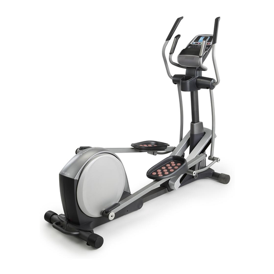
Thank you for selecting the revolutionary PROFORM manual. To help us assist you, note the product model ® 14.0 CE elliptical. The 14.0 CE elliptical provides an number and serial number before contacting us. The impressive selection of features designed to make model number and the location of the serial number your workouts at home more effective and enjoyable. -
Page 5: Assembly
ASSEMBLY Assembly requires two persons. Place all parts of the elliptical in a cleared area and remove the packing materials. Do not dispose of the packing materials until assembly is completed. In addition to the included tool(s) and grease packet(s), assembly requires a Phillips screwdriver and a rubber mallet Use the drawings below to identify the small parts needed for assembly. - Page 6 To make assembly easier, read the information on page 5 before you begin. Orient the Rear Stabilizer (4) as shown. Handle Attach the Rear Stabilizer (4) to the Folding Frame (2) with two M10 x 95mm Patch Screws (100). Next, hold the handle on the Rear Stabilizer (4), press the Latch Button (67), and lower the Rear Stabilizer and the Folding Frame (2) to the floor.
- Page 7 3. See drawing 3a. Identify and orient the Upright (5) and the Top Cover (27) as shown. Wire Tie Slide the Top Cover (27) upward onto the Upright (5). Have a second person hold the Upright (5) and the Top Cover (27) near the Main Frame (1). Locate the wire tie in the Upright (5).
- Page 8 4. Using a small plastic bag to keep your fingers clean, apply a coat of the included grease to the Upright Axle (48) and to two Wave Washers (118). Avoid damaging the Wire Harness (60) Tip: Avoid damaging the Wire Harness (60). Insert the Upright Axle (48) through the Upright (5) and center it.
- Page 9 6. Apply grease to the axle on the right Crank Arm (39). Orient a Pedal Arm Sleeve (46) so that the flat side is facing the elliptical. Slide the Pedal Arm Sleeve onto the axle on the right Crank Arm (39).
- Page 10 8. Orient the Ramp Cover (131) around the Upright (5) as shown. Press the tabs on the Ramp Cover (131) into the Ramp (130). 9. Apply grease to a Link Arm Axle (114). Insert the Link Arm Axle (114) into the Right Upper Body Leg (6) and the Right Link Arm (43) from the side shown.
- Page 11 10. Identify the Right Upper Body Arm (8), which is marked with a “Right” sticker, and orient it as shown. Have a second person hold the Right Upper Body Arm (8) near the Right Upper Body Leg (6). Attach the Right Upper Body Arm (8) to the Right Upper Body Leg (6) with three M8 x 16mm Patch Screws (102) and three M8 Split Washers (103).
- Page 12 12. Orient the Rear Upright Cover (25) as shown. Attach the Rear Upright Cover (25) to the Upright (5) with four M4 x 19mm Screws (156). 13. Untie and discard the wire tie attached to the Wire Harness (60). Avoid pinching the wires While a second person holds the Console (33) near the Upright (5), connect the wires on the...
- Page 13 14. Orient the Front Upright Cover (24) as shown. Attach the Front Upright Cover (24) around the Upright (5) by pressing the tabs on the Front Upright Cover into the Rear Upright Cover (25). 15. Make sure that all parts of the elliptical are properly tightened. Note: An extra grease packet and some hardware may be left over after assembly is completed.
-
Page 14: How To Use The Elliptical
HOW TO USE THE ELLIPTICAL HOW TO PLUG IN THE POWER CORD HOW TO FOLD AND UNFOLD THE ELLIPTICAL This product must be grounded. If it should mal- When the elliptical is not in use, the frame can be function or break down, grounding provides a path of folded out of the way. - Page 15 HOW TO MOVE THE ELLIPTICAL HOW TO EXERCISE ON THE ELLIPTICAL To move the elliptical, first fold it as described on page To mount the elliptical, hold the upper body arms and 14. Next, stand in front of the elliptical, hold the step onto the pedal that is in the lowest position.
- Page 16 CONSOLE DIAGRAM FEATURES OF THE CONSOLE The console also features an iFit Live mode that enables the console to communicate with your wire- The advanced console offers an array of features less network through an optional iFit Live module. designed to make your workouts more effective and With the iFit Live mode, you can download personal- enjoyable.
- Page 17 HOW TO TURN ON THE POWER 3. Change the resistance of the pedals and the incline of the ramp as desired. IMPORTANT: If the elliptical has been exposed to cold temperatures, allow it to warm to room tem- As you pedal, change the resistance of the pedals perature before turning on the power.
- Page 18 Pulse—This display mode will show your heart Press the Home button to exit the manual mode or rate when you use the handgrip heart rate monitor a workout and return to the default menu (see (see step 5). HOW TO CHANGE CONSOLE SETTINGS on page 22 to set the default menu).
- Page 19 HOW TO USE AN ONBOARD WORKOUT If the display does not show your heart rate, make sure that your hands are positioned as described. 1. Begin pedaling or press any button on the Be careful not to move your hands excessively or console to turn on the console.
- Page 20 During the If the resistance level or incline level for the cur- workout, rent segment is too high or too low, you can the profiles manually override the setting by pressing the on the Digital Resistance buttons or the Power Ramp but- tons.
- Page 21 HOW TO USE AN IFIT LIVE WORKOUT When you select an iFit Live workout, the display will show the duration of the workout and the You must have an iFit Live module to use an iFit Live approximate number of calories you will burn. The workout.
- Page 22 HOW TO USE THE SOUND SYSTEM 2. CONTRAST LVL: The display will show the con- trast level of the display. Press the Power Ramp To play music or audio books through the console increase and decrease buttons to adjust the con- sound system while you exercise, plug the included trast level.
-
Page 23: Maintenance And Troubleshooting
MAINTENANCE AND TROUBLESHOOTING Inspect and tighten all parts of the elliptical regularly. Replace any worn parts immediately. To clean the elliptical, use a damp cloth and a small amount of mild soap. IMPORTANT: To avoid damage to the console, keep liquids away from the con- sole and keep the console out of direct sunlight. - Page 24 HOW TO ADJUST THE DRIVE BELT Loosen the Pivot Screw (97). Tighten the Belt Adjustment Screw (85) until the Drive Belt (38) is tight. If you can feel the pedals slip while you are pedaling, When the Drive Belt is tight, tighten the Pivot Screw. even when the resistance is adjusted to the highest level, the drive belt may need to be adjusted.
-
Page 25: Exercise Guidelines
EXERCISE GUIDELINES WARNING: Burning Fat—To burn fat effectively, you must exer- cise at a low intensity level for a sustained period of Before beginning this time. During the first few minutes of exercise, your or any exercise program, consult your physi- body uses carbohydrate calories for energy. - Page 26 SUGGESTED STRETCHES The correct form for several basic stretches is shown at the right. Move slowly as you stretch—never bounce. 1. Toe Touch Stretch Stand with your knees bent slightly and slowly bend forward from your hips. Allow your back and shoulders to relax as you reach down toward your toes as far as possible.
-
Page 27: Part List
PART LIST Model No. PFEL18010.2 R0611A Key No. Qty. Description Key No. Qty. Description Main Frame Large Latch Spring Folding Frame Latch Insert Front Stabilizer Long Latch Spring Rear Stabilizer Arm/Leg Bushing Upright M4 x 16mm Flat Head Screw Right Upper Body Leg Small Axle Cover Left Upper Body Leg Upright Bushing... - Page 28 Key No. Qty. Description Key No. Qty. Description Small Pedal Arm Snap Ring Lift Motor M8 x 16mm Patch Screw Motor Wire Harness M8 Split Washer Ramp Roller Lift Arm Snap Ring Long Motor Axle Pulse Wire Short Motor Axle M4 x 16mm Screw Lift Axle Washer M10 x 20mm Button Screw...
-
Page 29: Exploded Drawing
EXPLODED DRAWING A Model No. PFEL18010.2 R0611A... - Page 30 EXPLODED DRAWING B Model No. PFEL18010.2 R0611A...
- Page 31 EXPLODED DRAWING C Model No. PFEL18010.2 R0611A...
-
Page 32: Ordering Replacement Parts
ORDERING REPLACEMENT PARTS To order replacement parts, see the front cover of this manual. To help us assist you, please be prepared to provide the following information when contacting us: • the model number and serial number of the product (see the front cover of this manual) •...