Advertisement
Table of Contents
- 1 Table of Contents
- 2 Warning Decal Placement
- 3 Important Precautions
- 4 Before You Begin
- 5 Part Identification Chart
- 6 Assembly
- 7 How to Use the Elliptical
- 8 Fcc Information
- 9 Maintenance and Troubleshooting
- 10 Exercise Guidelines
- 11 Part List
- 12 Exploded Drawing
- 13 Ordering Replacement Parts
- 14 Limited Warranty
- Download this manual
See also:
User Manual
www.proform.com
Model No. PFEL59911.3
Serial No.
USER’'S MANUAL
Write the serial number in the space
above for reference.
Serial Number Decal
(under frame)
ACTIVATE YOUR
WARRANTY
To register your product and
activate your warranty today,
go to www.proformservice.com/
registration.
CUSTOMER CARE
For service at any time, go to
www.proformservice.com.
Or call 1-888-533-1333
Mon.––Fri. 6 a.m.––6 p.m. MT
Sat. 8 a.m.––4 p.m. MT
Please do not contact the store.
CAUTION
Read all precautions and instruc-
tions in this manual before using
this equipment. Keep this manual
for future reference.
Advertisement
Table of Contents

Related Manuals for ProForm 18.0 Re Elliptical


Summary of Contents for ProForm 18.0 Re Elliptical
- Page 1 Model No. PFEL59911.3 Serial No. USER’’S MANUAL Write the serial number in the space above for reference. Serial Number Decal (under frame) ACTIVATE YOUR WARRANTY To register your product and activate your warranty today, go to www.proformservice.com/ registration. CUSTOMER CARE For service at any time, go to www.proformservice.com.
-
Page 2: Table Of Contents
If a decal is missing or illegible, see the front cover of this manual and request a free replacement decal. Apply the decal in the location shown. Note: The decal(s) may not be shown at actual size. PROFORM is a registered trademark of ICON IP, Inc. -
Page 3: Important Precautions
IMPORTANT PRECAUTIONS WARNING: To reduce the risk of burns, fire, electric shock, or injury to persons, read all important precautions and instructions in this manual and all warnings on your elliptical before using your elliptical. ICON assumes no responsibility for personal injury or property damage sus- tained by or through the use of this product. - Page 5 STANDARD SERVICE PLANS...
-
Page 6: Before You Begin
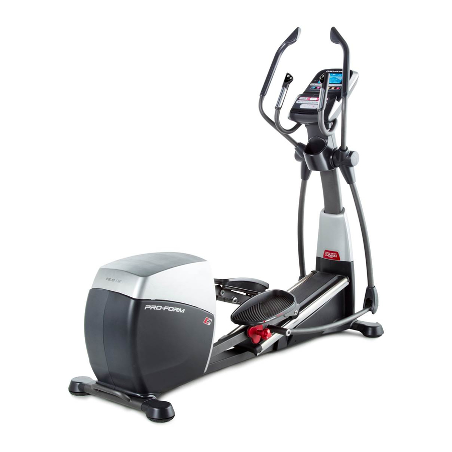
Thank you for selecting the revolutionary PROFORM ® manual. To help us assist you, note the product model 18.0 RE elliptical. The 18.0 RE elliptical provides an number and serial number before contacting us. The impressive selection of features designed to make your model number and the location of the serial number workouts at home more effective and enjoyable. -
Page 7: Part Identification Chart
PART IDENTIFICATION CHART Use the drawings below to identify the small parts needed for assembly. The number in parentheses below each drawing is the key number of the part, from the PART LIST near the end of this manual. The number following the key number is the quantity needed for assembly. -
Page 8: Assembly
ASSEMBLY •• To hire an authorized service technician to •• To identify small parts, see page 7. assemble this product, call 1-800-445-2480. •• In addition to the included tool(s), assembly •• Assembly requires two persons. requires the following tool(s): one Phillips screwdriver ••... - Page 9 3. Identify the two Rear Stabilizer Tubes (2). While a second person lifts the rear of the Frame (1), insert some packaging materials (not shown) under the Frame. Have the second person hold the Frame to prevent it from tipping. Attach a Rear Stabilizer Tube (2) to the Frame (1) with three M10 x 20mm Screws (91) and three M10 Split Washers (105).
- Page 10 5. Tip: Avoid pinching the wires. Slide the Upright (4) onto the Frame (1). Attach the Upright (4) with eight M10 x 20mm Screws (91) and eight M10 Split Washers (105). Avoid pinching Do not tighten the Screws yet. the wires Slide the Upright Cover (81) downward.
- Page 11 7. Using a plastic bag to keep your fingers clean, apply some of the included grease to the Long Axle (35) and to two 16mm Wave Washers (54) (only one is shown). Insert the Long Axle (35) through the Upright (4) and center it.
- Page 12 9. Identify the Right Pedal (49) and orient it as shown. While a second person lifts the Right Pedal Plate (14), attach the Right Pedal (49) to the Right Pedal Plate with four M6 x 16mm Screws (103) and four M6 Washers (90). Tip: It may be help- ful to lift the right Pedal Arm (44).
- Page 13 11. Apply grease to a Short Axle (149) and to two M8 x 22mm Washers (97). Next, tighten an M8 x 16mm Screw (82) and an M8 x 22mm Washer (97) a few turns into the Short Axle (149). While a second person holds the front end of the Right Link Arm (59) inside the bracket on the Right Upper Body Leg (60), insert the Short Axle (149) through both parts.
- Page 14 13. IMPORTANT: If you purchase the optional chest heart rate monitor (see page 27), see step 18 on page 16 to install the receiver included with the heart rate monitor. Orient the Rear Console Cover (80) as shown. Attach the Rear Console Cover (80) to the Upright (4) with four M4 x 16mm Screws (101).
- Page 15 15. Attach the Front Console Cover (79) around the Upright (4) by pressing the tabs on the Front Console Cover into the Rear Console Cover (80). 16. See step 6. Tighten the six M8 x 43mm Bolts (96). See step 5. Tighten the eight M10 x 20mm Screws (91).
- Page 16 If you purchase the optional heart rate monitor (see page 27), follow the step below to install the receiver included with the heart rate monitor. 18. Complete this step before you begin step 13. Note: It will be necessary to reverse steps 16, 15, 14, and 13 if you have already completed assembly.
-
Page 17: How To Use The Elliptical
HOW TO USE THE ELLIPTICAL HOW TO PLUG IN THE POWER CORD A temporary adapter may 2-pole Receptacle This product must be grounded. If it should malfunc- be used to tion or break down, grounding provides a path of least connect the Adapter resistance for electric current to reduce the risk of... - Page 18 HOW TO MOVE THE ELLIPTICAL HOW TO ADJUST THE POSITIONS OF THE PEDALS Due to the size and weight of the elliptical, moving Each pedal can it requires two persons. Stand in front of the elliptical, be adjusted to hold the upright, and place one foot against one of the several positions.
- Page 19 HOW TO EXERCISE ON THE ELLIPTICAL To mount the elliptical, hold the upper body arms or the handlebars and step onto the pedal that is in the lowest position. Next, step onto the other pedal. Push the ped- als until they begin to move with a continuous motion. Upper Body Arms Note: The pedal arms can turn in either direction.
- Page 20 CONSOLE DIAGRAM FEATURES OF THE CONSOLE The console also features revolutionary iFit technol- ogy that enables the console to communicate with your The advanced console offers an array of features wireless network through an optional iFit module. With designed to make your workouts more effective and the iFit mode, you can download personalized work- enjoyable.
- Page 21 HOW TO TURN ON THE POWER HOW TO USE THE MANUAL MODE IMPORTANT: If the elliptical has been exposed to 1. Begin pedaling or press any button on the cold temperatures, allow it to warm to room tem- console to turn on the console. perature before turning on the power.
- Page 22 4. Follow your progress with the display. Stride——This display mode will show the total num- ber of strides you have pedaled. The display can show the following workout information: Time——When the manual mode is selected, this display mode will show the elapsed time. When a workout is selected, this display mode will show the time remaining in the workout.
- Page 23 When a wireless iFit When your pulse is detected, a heart symbol in will module is connected, flash in the display each time your heart beats, one the wireless symbol at or two dashes will appear, and then your heart rate the top of the display will be shown.
- Page 24 HOW TO USE A PRESET WORKOUT the profile will begin to flash. If a different resis- tance level, ramp incline level, and/or target rpm is 1. Begin pedaling or press any button on the programmed for the next segment, the resistance console to turn on the console.
- Page 25 HOW TO USE AN IFIT WORKOUT of that type in your schedule. Press the Compete button to compete in a race that you have previ- You must have an iFit module to use an iFit workout. ously scheduled. For more information about the iFit workouts, please see www.iFit.com.
- Page 26 HOW TO CHANGE CONSOLE SETTINGS 5. Adjust the contrast level of the display if desired. The console features a user mode that allows you to view usage information, select a unit of measurement, Press the decrease button to view the contrast and adjust the contrast level of the display.
-
Page 27: Fcc Information
HOW TO USE THE SOUND SYSTEM THE OPTIONAL CHEST HEART RATE MONITOR To play music or audio books through the console Whether your sound system while you exercise, plug your audio goal is to cable into the jack on the console and into a jack on burn fat or to your MP3 player or CD player;... -
Page 28: Maintenance And Troubleshooting
MAINTENANCE AND TROUBLESHOOTING Inspect and tighten all parts of the elliptical regularly. HOW TO ADJUST THE REED SWITCH Replace any worn parts immediately. If the console does not display correct feedback, the To clean the elliptical, use a damp cloth and a small reed switch should be adjusted. - Page 29 Locate the Reed Switch (38). Loosen, but do not remove, the two M4 x 12.7mm Flange Screws (161). Next, rotate the Large Pulley (19) until a Magnet (43) is aligned with the Reed Switch (38). Slide the Reed Switch slightly toward or away from the Magnet. Then, retighten the M4 x 12.7mm Flange Screws (161).
-
Page 30: Exercise Guidelines
EXERCISE GUIDELINES Burning Fat——To burn fat effectively, you must exer- WARNING: cise at a low intensity level for a sustained period of Before beginning this time. During the first few minutes of exercise, your or any exercise program, consult your physi- body uses carbohydrate calories for energy. -
Page 31: Part List
PART LIST Model No. PFEL59911.3 R1212A Key No. Qty. Description Key No. Qty. Description Frame Pedal Arm Roller Rear Stabilizer Tube Ramp Arm Roller Ramp Ramp Arm Upright 16mm Wave Washer M4 x 19mm Screw Axle Cover Front Left Stabilizer Tube Large Arm Bushing Console Large Bearing... - Page 32 Key No. Qty. Description Key No. Qty. Description M4 x 16mm Screw Ramp Arm Clamp M8 Jam Nut M10 x 45mm Bolt M6 x 16mm Screw M10 x 35mm Bolt Power Switch M10 Square Nut M10 Split Washer Front Right Stabilizer Tube Shield Mount Right Track M4 x 12mm TZP Screw...
-
Page 33: Exploded Drawing
EXPLODED DRAWING A Model No. PFEL59911.3 R1212A... - Page 34 EXPLODED DRAWING B Model No. PFEL59911.3 R1212A...
- Page 35 EXPLODED DRAWING C Model No. PFEL59911.3 R1212A...
-
Page 36: Ordering Replacement Parts
ORDERING REPLACEMENT PARTS To order replacement parts, please see the front cover of this manual. To help us assist you, be prepared to provide the following information when contacting us: •• the model number and serial number of the product (see the front cover of this manual) ••...