
Summary of Contents for Aerobics Silver Select XP
- Page 1 PaceMaster Silver Select XP OWNER’S MANUAL Manufactured by: Aerobics Inc., 34 Fairfield Place West Caldwell, NJ 07006, (973) 276-9700 www.pacemaster.com Part # TMP1627 Rev. 09/01/09...
-
Page 2: Table Of Contents
Unpacking Your Treadmill Installation Requirements Tools Required for Assembly Grounding Instructions Assembly 7-14 Testing Your Treadmill THE PACEMASTER SILVER SELECT XP CONTROL PANEL 16-18 OPERATING INSTRUCTIONS 19-28 Metric Units Setting Your Weight and Age Warm Up and Cool Down Quick Start... -
Page 3: Introduction
We wish you an enjoyable and rewarding partnership with your PaceMaster treadmill. This treadmill is in compliance with EN 957-2 class H. The PaceMaster Silver Select XP treadmill is designed for home use only. -
Page 4: Important Safety Instructions
• Use your PaceMaster treadmill only for its intended use as described in this manual. Do not use accessories or attachments not recommended by Aerobics, Inc. • Never operate your PaceMaster treadmill if it has a damaged cord or plug, if it is not operating properly, if it has been dropped or damaged or if it has been immersed in water. -
Page 5: Assembly Instructions
ASSEMBLY INSTRUCTIONS Unpacking Your Treadmill Confirm that all of the items pictured below were packed in the box Control Panel Front Cup Holder w/ Foam Pad (2 pcs) Panel Support Tube (2 pcs) Side Rail (2 pcs) Control Panel Back Upright Assembly Handle Bar Motor Cover... -
Page 6: Installation Requirements
ASSEMBLY INSTRUCTIONS (cont’d) Installation Requirements Your PaceMaster should be installed indoors on a flat, level surface near a 120Volt/ 15Amp outlet. PaceMaster requires a dedicated, non- switched outlet that is not part of a GFI (Ground Fault Interrupter) circuit, preferably no more than 5 feet from the outlet to eliminate the need for an extension cord. -
Page 7: Assembly
ASSEMBLY INSTRUCTIONS (cont’d) Step One: Carefully place the bottom of the upright (1) on the frame (2) so the two holes in the plate at the bottom of the upright line up with the holes in the frame. Insert the 3.5” carriage bolts (3) through the upright and the frame. - Page 8 ASSEMBLY INSTRUCTIONS (cont’d) Purse Lock Clip CAUTION: Make sure the treadmill is NOT plugged into the electrical outlet until assembly is competed. Step Two: With the upright loosely bolted in place, plug the black wire harness (5) into the socket (6) on the power supply board.
- Page 9 ASSEMBLY INSTRUCTIONS (cont’d) Step Four: A. Remove the 3.5” Hex bolts (10) from both ends of handle bar (11). See FIG. A1. Place the Handle Bar (11) between the uprights (2) as shown in FIG. A2. Fig. A2 Fig. A1 Fig.
- Page 10 ASSEMBLY INSTRUCTIONS (cont’d) Step Five: Lower the top of the control panel (16) on to the upright assembly as shown below Step Six: Route the wire harness (8) as shown below. Pull the wire harness taut then apply tape #1 exactly as shown. Repeat and apply tape #2 exactly as shown.
- Page 11 ASSEMBLY INSTRUCTIONS (cont’d) Step Seven: Screw together the two halves of the control panel using the 14 one inch pan head screws (17). Start with the screw labeled 17 and proceed in a clockwise tightening sequence. Step Eight: Insert side rail spacer (18) onto the black panel support tube (12).
- Page 12 ASSEMBLY INSTRUCTIONS (cont’d) Step Nine: Insert one of the 4” slotted head bolts (20) through the side rail (19), the side rail bracket (21) (the foam on the bracket should be at the top, facing the frame) and finally through the frame (2).
- Page 13 ASSEMBLY INSTRUCTIONS (cont’d) Step Eleven: Insert the cup holder (23) into the hole in the control panel (16). Push down until you hear and feel it firmly snap in place. Note: The cup holder should sit flush to the control panel when it is snapped in place. If not, remove cup holder and rotate 180 degrees, then reinstall.
- Page 14 ASSEMBLY INSTRUCTIONS (cont’d) Step Thirteen: Assembly is complete, please proceed to testing your treadmill on the next page.
-
Page 15: Testing Your Treadmill
Testing Your Treadmill Your PaceMaster has been adjusted and tested at the factory. However, due to changes that can occur during shipment, it should be tested prior to use. Once you have assembled your treadmill and it is located where it will be used, proceed as follows. (Do not make any adjustments unless necessary.) For the purpose of this test, DO NOT stand on the tread belt. -
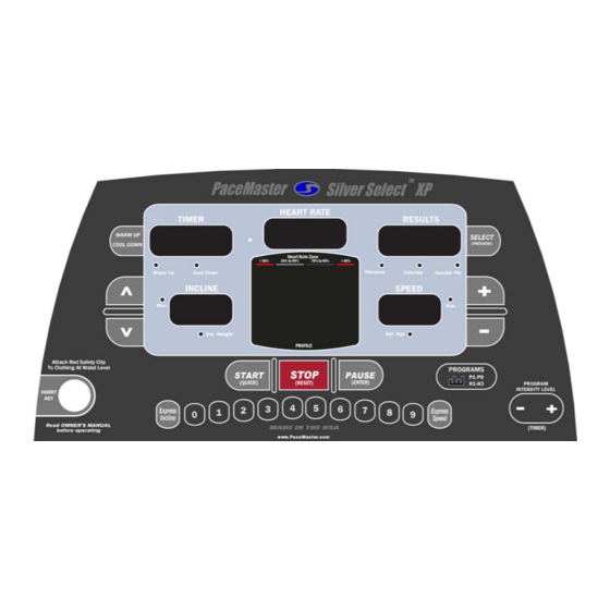
Page 16: The Pacemaster Silver Select Xp Control Panel
THE PACEMASTER SILVER SELECT XP CONTROL PANEL Although your PaceMaster has many advanced features to provide versatility in meeting exercise needs, basic operation is extremely easy. Basic operation involves setting your TIME and SPEED goals, then pressing the START button. Your PaceMaster will gradually accelerate to the set speed, maintain that speed until the timer counts to zero and then gradually come to a complete stop. - Page 17 THE PACEMASTER SILVER SELECT XP CONTROL PANEL (cont’d) PAUSE (ENTER) button – Has two functions. 1) It is used to ENTER your body weight and the program time for a workout. 2) During a workout, pressing this button will PAUSE your exercise, or put it "on hold". The treadmill stops but retains the distance, calories and Aerobic Points accumulated thus far, as well as the speed setting and remaining time.
-
Page 18: The Pacemaster Silver Select Xp Control Panel
THE PACEMASTER SILVER SELECT XP CONTROL PANEL (cont’d) SPEED display – Displays Speed from 0.5 mph to 11.0 mph, in 0.1 mph increments. Prior to starting, the displayed value is the Speed the treadmill will seek once START is pressed. Once your workout has begun, the current Speed is displayed. The speed display will flash until the set speed is reached. -
Page 19: Operating Instructions
OPERATING INSTRUCTIONS Initially, you may want to keep both hands on the side rails until you feel comfortable walking on your PaceMaster. Once you feel comfortable, try removing your hands to let them swing naturally, as you would when walking outdoors. Always hold on to the side rail or front handle bar with one hand when operating the buttons of the control panel. -
Page 20: Quick Start
QUICK START Quick Start allows you to begin your workout by pressing one button. You control the speed, incline and time. Step One: Stand on the running belt and attach the garment clip on the end of the magnetic safety key to your clothing. Insert the safety key into its recess on the control panel. -
Page 21: Timed Workout (Manual)
TIMED WORKOUT (MANUAL) Timed Workout allows you to choose the length of time and the degree of intensity for your workout. You can make speed and incline adjustments at any time during the workout. Step One: Stand on the running belt and attach the garment clip on the end of the magnetic safety key to your clothing. Insert the safety key into its recess on the control panel. -
Page 22: Programs
PROGRAMS To assist you in reaching your fitness goals, your PaceMaster comes with a variety of programmed workouts. You will be alerted to any speed and/or elevation changes in the workouts with 5 audible chirps and a flashing speed and/or incline display. P1 CALORIE COACH The Calorie Coach program enables you to select the number of calories you want to burn. -
Page 23: P2, P3, P4, P5, And P7
PROGRAMS (cont’d) USING P2, P3, P4, P5, and P7: Each of these programs offers 9 levels of intensity. Additionally, workout time can be set from 20 to 60 minutes in 5 minute increments. Step One: Stand on the running belt and attach the garment clip on the end of the magnetic safety key to your clothing. Insert the safety key into its recess on the control panel. -
Page 24: P8 And P9
PROGRAMS (cont’d) USING P6: This workout is a 5 kilometer run, the user sets speed and incline and the computer calculates the workout time. Step One: Stand on the running belt and attach the garment clip on the end of the magnetic safety key to your clothing. Insert the safety key into its recess on the control panel. - Page 25 PROGRAMS (cont’d) Step Four: Press the button to begin your program. TIP: You can pause your workout by pressing the PAUSE button. This feature is not available in warm up or heart rate control. To resume, press the START button. To restore a Body for Life recommended cardio workout after it has been Recorded over: Step One: P1-P9...
- Page 26 PROGRAMS (cont’d) can be also be made by using the buttons. For details, refer to Express buttons in this manual. Your workout will end when the button has been pressed. Stor will appear in the RESULTS display window, indicating that you have successfully recorded your custom program.
-
Page 27: Program Specifications
Program Specifications – P2, P3, & P4 Heart Rate Zone < 55% 55% to 69% 70% to 85% > 85% Level Speed Incline 10.0 11.0 12.0 13.0 PROFILE Heart Rate Zone < 55% 55% to 69% 70% to 85% > 85% Level Speed Incline... -
Page 28: Program Specifications - P5 & P7
Program Specifications – P5 & P7 Heart Rate Zone < 55% 55% to 69% 70% to 85% > 85% Level Speed Incline 10.0 PROFILE Heart Rate Zone < 55% 55% to 69% 70% to 85% > 85% Level Speed Incline PROFILE... -
Page 29: Heart Rate
The PaceMaster Silver Select XP has integrated heart rate control programs, which act as your personal trainer. You set your target based on your individual fitness goal (weight management or cardiovascular improvement), the time and maximum speed and incline parameters and the treadmill does the rest. - Page 30 HEART RATE PROGRAMS (cont’d) To begin using TARGET HRC, FAT BURN HRC, and CARDIO HRC: Step One: Put on the chest strap transmitter as pictured on page 23. Step Two: Stand on the running belt and attach the garment clip on the end of the magnetic safety key to your clothing. Insert the safety key into its recess on the control panel.
- Page 31 HEART RATE PROGRAMS (cont’d) Step Nine: button. After the warm up phase, you will see a graphic depiction of a heart and a ⊥ (the On-Target Indicator) in the Press the PROFILE display window. When your heart rate is at the target the ⊥ (On-Target Indicator) will be centered under the heart depicted in the Profile display.
-
Page 32: Exclusive Pacemaster Features
PaceMaster computer to automatically calculate the number of AEROBIC POINTS you earn for each workout Dr. Cooper states in his book, The Aerobics Program For Total Well Being; “The main idea of this system is that, in order to stay in good shape and move toward a goal of total well-being, a person must earn a certain number of points each week by doing a certain amount of aerobic exercise.”... -
Page 33: Exclusive Pacemaster Features
EXCLUSIVE PACEMASTER FEATURES (cont’d) Step Three: Press the Incline buttons to set your weight and the Speed buttons to set your age, then press the button. Step Four: Enter the workout time by pressing the PROGRAM INTENSITY LEVEL (TIMER) buttons until the desired workout time appears, you may also add a warm up and/or cool down. -
Page 34: Care And Maintenance
Care and Maintenance The following section describes necessary maintenance for your PaceMaster treadmill. This maintenance is the responsibility of the purchaser and is not covered under our warranty. Failure to perform this necessary maintenance could result in damage to your treadmill. CAUTION: Unplug your treadmill before attempting any cleaning or maintenance. -
Page 35: Cup Holder
Care and Maintenance (cont’d) CUP HOLDER Installation: Simply place cup holder with the black foam pad into the hole in the control panel. Press down until you hear the cup firmly snap into place. Note: The cup holder should sit flush to the control panel when it is snapped in place. -
Page 36: Troubleshooting
TROUBLESHOOTING CAUTION: Unplug your treadmill before attempting any cleaning, maintenance, or service. Is the magnetic key inserted into the control panel? Is treadmill plugged into the wall outlet? Check the household circuit breaker to see if it is tripped. The treadmill may not operate if plugged into a GFCI (Ground Fault Current Interrupt) outlet. -
Page 37: Elevation Error Codes
TROUBLESHOOTING (cont’d) CAUTION: Unplug your treadmill before attempting any cleaning, maintenance, or service. Error Code 133 or 134 This is a communication error that could be a result of the black wire harness not being plugged in all the way. Unplug the treadmill from the wall outlet and reconnect the black wire harness that you plugged in during Step Two of assembly, see page 6. -
Page 38: Noises
TROUBLESHOOTING (cont’d) Noises A Clicking, Rubbing or Grinding noise is present while the tread belt is moving. Remove all items from the cup holders on either side of the display Visually confirm that NO foreign objects (children’s toys, pet’s toys, etc…) are underneath, on top of, or against the treadmill. With the tread belt stopped visually check to see if the tread belt is reasonable centered, if it is not please refer to “centering the tread belt”... -
Page 39: Tread Belt Tension Adjustment
TROUBLESHOOTING (cont’d) Step Three: (figure 8) Locate the drive belt adjustment screw (item 2 in fig 8) in the lower front end of the treadmill. Insert the allen wrench into the drive belt adjustment screw and turn the screw 1/2 turn clockwise. Step Four: (figure 7) Complete the adjustment by tightening the four motor mount screws (item 1 in fig 7). -
Page 40: Frequently Asked Questions
FREQUENTLY ASKED QUESTIONS Q. Why is time displayed as a negative number (i.e. 1:15)? – A. The treadmill’s computer displays time in minutes and seconds (MM:SS) for workout times less than 1 Hour, and in hours and minutes ( H:MM) for workout times 1 hour or greater. 1:15 represents one hour and 15 minutes. -
Page 41: Pacemaster Technical Specifications
Lifetime Frame, 12 Years Motor, 5 Years Parts, 1 Year Labor Warranty (Institutional) None Operating Temperature Range 50º F to 100º F Manufacturer reserves the right to change the products specifications without notice. © Aerobics, Inc. 2009 PaceMaster is a registered trademark of Aerobics Inc.