Citizen CL-S400DT User Manual
Thermal label & barcode printer
Hide thumbs
Also See for CL-S400DT:
- Technical manual (164 pages) ,
- Quick start manual (2 pages) ,
- Programming manual (95 pages)
Table of Contents
Advertisement
Advertisement
Table of Contents

Related Manuals for Citizen CL-S400DT


Summary of Contents for Citizen CL-S400DT
- Page 1 Thermal Label & Barcode Printer CL-S400DT SER'S ANUAL...
-
Page 2: Table Of Contents
CONTENTS Before Operation INTRODUCTION ..........................3 COMPLIANCE STATEMENT FOR EUROPEAN USERS ............4 GS MARK STATEMENT ........................4 FCC COMPLIANCE STATEMENT FOR AMERICAN USERS ........... 4 EMI COMPLIANCE STATEMENT FOR CANADIAN USERS ........... 5 ETAT DE CONFORMITE EMI A L’USAGE DES UTILISATEURS CANADIENS ....5 IMPORTANT SAFETY INSTRUCTIONS ..................6 NOTICE ............................... 7 SAFETY INSTRUCTIONS ........................ 8 Chapter 1 Setup Confirmation of Carton Contents ..................10 Part Names and Functions ......................12 Connection to Power ........................16 Driver Installation ........................16 Connection to a Computer .......................17 Chapter 2 Printer Operation Power ON/OFF ..........................18 Normal Operating Mode . -
Page 3: Introduction
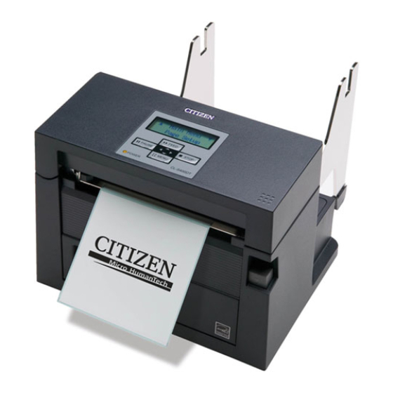
INTRODUCTION Thank you very much for purchasing Citizen’s compact direct thermal label & barcode printer Model CL-S400DT that offers high performance printing at 6 inches per second on 4.1 inch media at very low cost. ■■■ ■■■ Main Features <High-speed, high-quality printing> This printer can be used for high-speed high-quality printing thanks to its thermal-transfer system that uses a line thermal printhead together with its 32 bit RISC CPU and its ‘history control IC’ . <Easy operation> • You can carry out all the daily operations of the printer by using the operation panel on the upper side of the printer. The power switch is also on the front side of the printer, and the access to the switch is therefore easy. • The clear, easy-to-see backlit LCD makes both configuration and operation easy with simple messages about the printer’s status and also the ability for quick configuration when needed. • You can easily change the setting of the printer by operating the operation panel. • Its high-lift printhead and mechanism means that media can be loaded with ease and it is constructed for easy thermal printhead cleaning, etc. • Media width adjustment, media thickness adjustment, and media sensor adjustment can all be made easily by the user. <Dual Programming Language> This printer contains both the Datamax® and Zebra® emulations and will automatically detect the language using the Cross-Emulation™ feature. <Interface> An industry standard RS232 serial port and USB2.0 port are standard equipment, for quick data transfer and printing. <Optional interface>... -
Page 4: Compliance Statement For European Users
COMPLIANCE STATEMENT FOR EUROPEAN USERS CE marking shows conformity to the following criteria and provisions: Low Voltage Directive (2006/95/EC, formerly 73/23/EEC)/EN60950-1 EMC Directive (2004/108/EC, formerly 89/336/EEC)/EN55022, EN55024, EN61000-3-2 & EN61000-3-3 GS MARK STATEMENT This product has been tested under EN ISO 7779 and has an acoustic level output no higher than 55db(A). This device is not intended for use at a video workstation in compliance with Bildscharb V. This device is not intended for use in the direct field of view at visual display workplaces. To avoid incommoding reflections at visual display workplaces this device must not be placed in the direct field of view. FCC COMPLIANCE STATEMENT FOR AMERICAN USERS This equipment has been tested and found to comply with the limits for a Class A digital device, pursuant to Part 15 of the FCC Rules. These limits are designed to provide reasonable protection against harmful interference when the equipment is operated in a commercial environment. This equipment generates, uses, and can radiate radio frequency energy and, if not installed and used in accordance with the instruction manual, may cause harmful interference to radio communications. Operation of this equipment in a residential area is likely to cause harmful interference in which case the user will be required to correct the interference at his own expense. * The model name printed on the CL-S400DT rating label is JP12-M01. -
Page 5: Emi Compliance Statement For Canadian Users
EMI COMPLIANCE STATEMENT FOR CANADIAN USERS This Class A digital apparatus complies with Canadian ICES-003. This equipment generates and uses radio frequency energy and if not installed and used properly, that is, in strict accordance with the manufacturer’s instructions, may cause interference to radio and television reception. This digital apparatus does not exceed the Class A limits for radio noise emissions from digital apparatus set out in the Radio Interference Regulations of the Canadian Department of Communications. This equipment is designed to provide reasonable protection against such interference in a residential installation. However, there is no guarantee that interference will not occur in a particular installation. If this equipment does cause interference to radio or television reception, which can be determined by turning the equipment off and on, the user is encouraged to try to correct the interference by one or more of the following measures:... -
Page 6: Important Safety Instructions
IMPORTANT SAFETY INSTRUCTIONS • Read all of these instructions and save them for later reference. • Follow all warnings and instructions marked on the product. • Unplug this product from the wall outlet before cleaning. Do not use liquid or aerosol cleaners. Use a damp cloth for cleaning. • Do not use this product near water. • Do not place this product on an unstable cart, stand or table. The product may fall, causing serious damage to the product. • Slots and openings on the cabinet and the back or bottom are provided for ventilation. To ensure reliable operation of the product and to protect it from overheating, do not block or cover these openings. The openings should never be blocked by placing the product on a bed, sofa, rug or other similar surface. This product should never be placed near or over a radiator or heat register. This product should not be placed in a built-in installation unless proper ventilation is provided. • This product should be operated from the type of power source indicated on the marking label. If you are not sure of the type of power available, consult your dealer or local power company. • This product is equipped with a three-pronged plug, a plug having a third (grounding) pin. This plug will only fit into a grounding-type power outlet. This is a safety feature. If you are unable to insert the plug into the outlet, contact your electrician to replace your obsolete outlet. Do not defeat the safety purpose of the grounding-type plug. • Do not allow anything to rest on the power cord. Do not locate this product where the cord will be walked • If an extension cord is used with this product, make sure that the total of the ampere ratings on the products plugged into the extension cord do not exceed the extension cord ampere rating. Also, make sure that the total of all products plugged into the wall outlet does not exceed 15 amperes for 120V outlet and 7.5 amperes for 220V-240V outlet. • Never push objects of any kind into this product through cabinet slots as they may touch dangerous voltage points or short out parts that could result in a risk of fire or electric shock. Never spill liquid of any kind on the product. • Except as explained elsewhere in this manual, don't attempt to service this product yourself. Opening and removing those covers that are marked "Do Not Remove" may expose you to dangerous voltage points or other risks. Refer all servicing on those compartments to service personnel. -
Page 7: Notice
• We are not liable for any damage caused by user's erroneous use of the printer and inadequate environment. • Data residing in the printer is temporary. Therefore, all data will be lost if power is lost. We are not liable for any damage or loss of profits caused by data loss due to failures, repairs, inspections, etc. • Please contact us if there are any mistakes or ambiguities within this manual. • If there are missing or incorrectly collated pages in this manual, contact us to obtain a new manual. CITIZEN is a registered trademark of CITIZEN HOLDINGS CO., Japan. CITIZEN es una marca registrada de CITIZEN HOLDINGS CO., Japón. Copyright © 2011 by CITIZEN SYSTEMS JAPAN CO., LTD. -
Page 8: Safety Instructions
SAFETY INSTRUCTIONS which must be strictly observed ! • To prevent personal injury or property damage, the following shall be strictly observed. • The degree of possible injury and damage due to incorrect use or improperly following instructions is described below. Indicates a situation which, if not observed and handled Warning properly, could result in death or serious injury. -
Page 9: General Precautions
General Precautions Caution • Prior to operation, read the safety instructions carefully and observe them. • Do not drop or put foreign matter such as clips and pins into the printer. This may cause problems. • Be careful when moving or carrying the printer. Dropping the printer may cause injury or property damage. • Make sure if you open the top cover, it is opened all the way. If only partially open, the cover could slam shut, possibly causing injury. • When the cover is open, be careful of the corners of the cover. They could cause injury. • Do not open the printer during printing. • When cleaning the surface of the printer case, do not use the cloth that is soaked in thinner, trichloroethylene, benzine, ketone or similar chemicals. • Do not use the printer where there is a lot of oil, iron particles, or dust. • Do not spill liquids or spray insecticide on the printer. • Do not jolt or impact to the printer by stepping on, dropping or hitting the printer. • Operate the control panel properly. A careless, rough handling may cause problems or malfunction. Do not use such sharp-edged tool as a ballpoint pen for operation. • Be careful of the edges of the plates so injury or property damage is possible. • If a problem occurs during printing, stop the printer immediately and unplug the power cord from the outlet. • When printer trouble occurs, do not try to dissemble it. Instead, consult our service personnel. Precautions When Installing the Printer Caution • Prior to operation, read the safety instructions carefully and observe them. -
Page 10: Chapter 1 Setup
Chapter 1 Setup Chapter 1 Setup Confirmation of Carton Contents Removing the Packing Material The printer is shipped with adhesive tape in place to hold the top cover closed. Simply remove the two pieces of tape on either side of the top cover. Then simply open the cover by lifting up and tipping it backwards. There is another strip of adhesive tape that must be removed which holds the mechanism closed for shipping. Remove the tape and attached paper by carefully peeling from the plastic case. Retain the tape should you need to transport the printer again. Check that the following accessories are included with the printer in the carton. Media holder guide Media holder bar Test label media Power cord CD-ROM... - Page 11 Chapter 1 Setup Caution • Be careful when moving or carrying the printer and when taking the printer out of the carton. The printer may cause injury or property damage if dropped. Be sure to grip the printer housing firmly when taking it out of the carton. Do not grip the printer by the packing material which may break, causing the printer to drop. • When opening the cover, open it all the way. If only part way open, the cover could slam shut, possibly causing injury. • Be careful of the edge of the cover when the cover is opened. It may cause injury or property damage. • Be careful of the edges of the metal plates so injury or property damage is possible.
-
Page 12: Part Names And Functions
Chapter 1 Setup Part Names and Functions Front View 1 Printer cover Is opened vertically to place or replace media. 2 Operation panel Operation Panel (p.14) This is used to make changes and adjustments to the printer and its configuration. 3 Power switch Power ON/OFF (p.18) This is the power switch for the printer. 4 Cover open lever The printer cover can be raised to install media by pushing this lever. It locks the head unit during printing. - Page 13 Chapter 1 Setup Part Names and Functions Inside the printer 1 Thermal printhead Installing the Media (p.22) This is the printhead. Avoid touching this with your fingertips and leaving grease or dirt on the printhead surface. 2 Media guides (Left fixed media guide ( 2 ) and right movable media guide ( 2 The end of the media is matched to the left fixed media guide, then the right side movable media guide is moved horizontally to match it to the media size. 3 Front cover It is removed to install optional units such as the peeler or cutter.
-
Page 14: Operation Panel
Chapter 1 Setup Part Names and Functions Operation Panel FEED PAUSE STOP MENU POWER 1 LCD display LED Functions (p.20) This displays the operational status of the printer. 2 FEED key This key feeds the media to the top of the next label or form. 3 PAUSE key Normal Operating Mode (p.19) This temporarily stops printing. 4 POWER LED LED Functions (p.20) This is lit when the printer power is on. (green) This is lit when the printer is in an alarm or error status. (red) 5 STOP key This stops printing or cancels the alarm. -
Page 15: Rear View
Chapter 1 Setup Part Names and Functions Rear View 1 Media holder bar The media is supported by the media holder bar when installed in the printer. 2 Media holder guide This guide is moved horizontally to match the media size. The guide can be sliding it from the holder bar. 3 Media holder stand It is a base to mount the media holder bar. 4 Serial interface (RS232C) Serial Interface (p.57) This receives serial transmission of data from a host computer. 5 Media width adjustment dial Media Width Adjustment (p.49) It is adjusted to match the width of the media. -
Page 16: Connection To Power
Chapter 1 Setup Connection to Power 1. Check that the power switch to the printer is turned OFF. 2. Connect the connector of the power cord to the power cord inlet on the printer. 3. Insert the plug of the power cord in the AC outlet. AC Outlet Power Cord Inlet Caution Use an AC outlet that accepts a three-pronged plug. Otherwise, static electricity may be generated and there will be danger of electric shock. Driver Installation The computer may automatically detect the presence of the new printer when it is first started, depending on the computer type, interface and operating system. Follow any on-screen instruction and also instructions supplied with any additional CD-ROM included with your printer. Your supplier will assist you with the correct drivers and software which are compatible with your particular computer system. -
Page 17: Connection To A Computer
Chapter 1 Setup Connection to a Computer This product has two interfaces that can be used to receive printing data: a serial port (RS232C) and a USB port (USB2.0). An optional internal Ethernet or an IEEE1284 Parallel port can be added by your dealer. To connect the cable, proceed as follows: 1. Turn OFF both power switches of the printer and the computer. 2. Connect one end of the interface cable to the interface connector on the back of the printer and secure it with locks or locking screws, where available. 3. Connect the other end of the interface cable to the interface connector on the computer and secure it with locks or locking screws, where available. Serial Interface (p.57) USB Interface (p.59) Serial Interface Cable USB Interface Cable Note: If the optional Ethernet or an IEEE1284 Parallel port is used, contact your Citizen Systems dealer. -
Page 18: Chapter 2 Printer Operation
Chapter 2 Printer Operation Chapter 2 Printer Operation Power ON/OFF Turning on the power 1. The power switch is conveniently located at the front of the printer for easy access during normal operation. It is in the recess underneath the control panel so it cannot be accidentally operated by mistake. 2. The POWER LED lights up. PAUSE POWER Power Switch Turning off the power 1. Turn off the power switch of the printer. 2. The POWER LED goes off. Power Switch... -
Page 19: Normal Operating Mode
Chapter 2 Printer Operation Normal Operating Mode Menu Setup Mode (p.28) When the power is turned on, the printer enters normal operating mode. The control keys activate the following functions. FEED PAUSE STOP MENU POWER 1 PAUSE key: Temporarily pauses printing • When this key is pushed once, the LCD indicates “Pause” and the printer temporarily pauses. • When it is pushed during printing, the printer pauses after the label currently being printed is issued. Pressing the key a second time restarts printing and the remaining number of designated labels are printed. 2 FEED key: Feeds media • Pressing this key feeds media to the print start position. The distance it is fed is determined by automatically detecting the front end of the media when using label media, and when continuous media has been designated, a fixed quantity is fed, then feeding stops. - Page 20 Chapter 2 Printer Operation Normal Operating Mode LED Functions In addition to normal operating mode, FEED when an abnormal condition is detected PAUSE STOP in the printer, an alarm sounds and the POWER LED lights up (red) to indicate the MENU POWER LED type of error. The LCD indicates the error POWER message. Table of Alarm and Error Indications Item POWER LED Lights up On Line Printing possible (no error) (green) Ready Lights up STOP or PAUSE key on operation panel pressed Pause (green) Head temperature - high temperature Alarm Lights up (red) abnormality...
-
Page 21: Setting The Media
Chapter 2 Printer Operation Setting the Media Media Sizes The position of label and tag media is sensed by either a transparent sensor or a reflective sensor. Transparent sensor: Detects the gaps between label media and notches of tag media Reflective sensor: Detects the black mark Continuous media Label media Notch detection Black mark detection Label Printed area Label Label Transparent sensor Re ective sensor Media direction Min. value mm (inches) Max. value mm (inches) Label width 19.50 (0.77) 118.00 (4.65) Liner width... - Page 22 Chapter 2 Printer Operation Setting the Media Installing the Media 1. Push the cover open lever to release the printer cover. It can be opened to the position shown below by lifting the printer cover by hand. Cover open lever 2. Setting sensor positions. Sensor Selection Method (Transparent Reflective) When using a transparent sensor (p.45) 1 Move the bottom sensor to the middle of the width of the Adjusting the Transparent media. sensor (p.46) Adjust it to the middle of the width of the media.
- Page 23 Chapter 2 Printer Operation Setting the Media 2 Then, regulate the position of the upper sensor so that the upper sensor marker scale indicates the same value as the scale of the bottom sensor scale. Set it to the same value as the bottom sensor scale. <In case the position of the bottom sensor scale is 3.5> When using media that is 4 inches wide, position the upper sensor and the bottom sensor all the way to the right (cover open lever side). Adjusting the Reflective sensor ...
- Page 24 Chapter 2 Printer Operation Setting the Media 3. Set the media on the printer. Firstly, slide the two black plastic parts of the media holder assembly together. Ensure correct alignment of the guide with the bar as it can only be installed in one direction. 4. Slide the roll of media over the media bar. The media guide must be on the right side of the roll of media (as viewed from the front of the printer) with the ribbed surface of the media guide touching the media roll as shown in the illustration. Media holder guide Media holder bar Media Sizes (p.21) 5. Set the media roll and media holder in to the printer as shown above. It is advisable to pull a length of media forwards and through the mechanism ready for later positioning. 6. Move the media roll so it is touching the left side of the housing. Then slide the black media guide so it is touching the media on the right side. Do not try to hold the media too tightly with these guides as it will cause the printer to jam during printing.
- Page 25 Chapter 2 Printer Operation Setting the Media 7. Align the media with the left fixed media guides (2 places), and align the right movable media guide with the media width. Note: Make sure to set the media following the procedure as indicated here. If not, it may jam. Fixed media guide Fixed media guide Movable media guide 8. Lower and lock the printer cover. Align it with the width of Adjusting the Transparent sensor (p.46) the media that has been set, then set the media width and media thickness adjustment dials. Adjusting the Reflective sensor (p.47) See “Chapter 3 Printer Adjustments”. Media width adjustment Media thickness adjustment 9. With the power switched on, push the FEED key to feed the media. It will halt at the next print start position.
-
Page 26: Mode Settings
Chapter 2 Printer Operation Mode Settings Operation Panel (p.14) Turning on the power while pressing keys in the following combinations starts various functions. Mode Key operation HEX dump mode Turning power on while pushing the STOP key. Self print mode Turning power on while pushing the FEED key. Menu list print mode and Turning power on while pushing the MENU key. Menu setup mode HEX Dump Mode When using label media Turn on printer power while pushing the STOP key. If the POWER LED lights up and the LCD indicates “Hex Dump Mode” and “Label Media”, release the STOP key, and then the printer enters HEX DUMP mode. When using continuous media Turn on printer power while pushing the STOP key. If the POWER LED lights up and the LCD indicates “Hex Dump Mode” and “Label Media”, and then changed to “Hex Dump Mode” and “Cont. Media”, release the STOP key, and then the printer enters HEX dump mode. DUMP LIST * To exit HEX Dump Mode, turn off the power to the printer then turn the power on again (restart). - Page 27 Chapter 2 Printer Operation Mode Settings Self Print Mode Performing a self test print is an easy way to check on the state of printer setting and printing quality. Install the media as explained in “Installing the Media” and then operate the printer as follows. Case of label media Installing the Media (p.22) Turn on printer power while pushing the FEED key. When the LCD indicates “Self Print Mode” and “Label Media”, release the FEED key. After it enters TEST MODE and media has fed, two labels print then printing stops. To restart printing, press the FEED key once more. Media feed Case of continuous media direction Turn on printer power while pushing the FEED key. When the LCD indicates “Self Print Mode”...
- Page 28 Chapter 2 Printer Operation Mode Settings Menu Setup Mode If the MENU key is pressed while the printer is in the On Line Ready state, the printer enters menu setup mode. In this mode, the printer’s configuration can be changed using the operation panel. During menu setting mode, the LCD indicates the current menu settings and the key function. Shift/Change FEED Enter/Save Exit PAUSE STOP MENU POWER Shift/Change Functions of the keys When you enter Menu Setup Mode, the LCD displays “Main Menu” on the top line and Page Setup below. In the menu setup mode, the four keys become “cursor keys” to navigate the menu. Refer to the four small arrows in the centre of the keypad rather than the names of the keys. FEED key (Shift/Change): The key (FEED key) goes up the menu system or selects a higher value MENU key (Shift/Change): The ...
- Page 29 Chapter 2 Printer Operation Mode Settings Example of changing a menu This is an explanation of the method of changing the set value of print darkness from “12” to “14” in a case where the main menu is “Page Setup” and the sub menu is “Print Darkness”. 1. Entering Menu Setup Mode. Ensure LCD displays “On Line Ready”. Then press the MENU key to enter ‘menu setup mode’ where the printers settings can be changed or confirmed. Main Menu Page Setup On Line Ready The current main menu is displayed. FEED The following are the functions of each key. STOP PAUSE ▲key: displays the previous menu item...
- Page 30 Chapter 2 Printer Operation Mode Settings 2. Entering Sub menu. Press the key. The currently set item, “Print Speed”, is displayed. Page Setup Print Speed The following are the functions of each key. key: displays the previous sub menu key: displays the next sub menu key: displays the values set by the selected sub menu key: returns to the main menu 3. Selecting “Print Darkness” from the sub menu. Press the key one time to display “Print Darkness”. It is the second item within “Page Setup”. Page Setup Print Darkness 4. Displaying the set value of “Print Darkness”. Press the key and the value “12” - the currently set value - is displayed.
- Page 31 Chapter 2 Printer Operation Mode Settings 6. Save Changes to Settings. Unless you save your settings, your changes will be lost when you turn off the printer. To Save Changes 1 Press the key twice to display Save Settings the message “Save Settings No- No-Discard Discard”. 2 Press the key or the key Save Settings to display the message “Save Yes-Save Settings Yes-Save”. 3 Press the key. On Line The new settings will be saved Ready and the printer will return to the...
- Page 32 Example of changing a menu (p.29) You can get a list of the configuration settings in two ways: - Press MENU key whilst turning the printer on. The POWER LED lights up and “Print Settings” is displayed on the LCD. After printing, the printer will enter Menu Setup Mode. - You can access the configuration print via the “Test Mode, Print Pattern, Current Config” from the setup menu. Machine Information Model Number : CL-S400DT Boot Version : **** ROM Version : ******** ROM Date(DD//MM//YY) : XX/XX/XX ROMCheck Sum : **** FPGA Version : ****.****...
- Page 33 Chapter 2 Printer Operation Mode Settings Global Configuration Sets The printer can store three sets of configuration settings that can be recalled quickly and easily. Each “Config Set” (1, 2 or 3) can contain completely different configuration settings for all menu parameters. For example, “Config Set 1” could be configured for 4 ips print speed, print darkness 18. “Config Set 2” next could be 5 ips continuous card media with black mark, print darkness 12. The ability of having three sets of settings is ideal for someone who prints on different media types regularly, for example in a label printing bureau. Global config settings can be printed using the “Test Mode, Print Pattern, Global Config” menu option. It will also display the currently active “Config Set”: Global Menu Settings Active Configuration Setting Config 1 Config 2 Config 3 [PageSetup Menu] Print Speed Print Darkness Darkness Adjust Continuous Media Length 04.00inch 04.00inch 04.00inch...
- Page 34 Chapter 2 Printer Operation Mode Settings [Datamax® Emulation] Menu Setting Table Page Setup Menu - allows you to change settings related to the media or print quality. System Setup Menu - allows you to change settings for the printer hardware and basic control systems. After Print Menu - changes how the printer reacts after the label has been printed. Interfaces - changes interface parameters such as baud rate. Machine Information, Test Mode - allows you to check and/or print test pages and information about the printer. Global Config menu - allows you to switch between 3 complete ‘config sets’ contained within the printer. Menu Setting Press the MENU key in print possible status to enter MENU Setup Mode. Use the keys on the operation panel according to the LCD display to setup the printer. The contents that can be setup on the printer are shown below. And the items that are actually displayed on the LCD are shown in [ ]. Datamax® Emulation Top Menu Sub Menu Default Menu Remarks Page Setup Print Speed* 6 IPS 2 to 6 IPS Printing speed setting. Print Darkness 00 to 30 Adjusting print darkness. Darkness Adjust -10 to 10 Fine adjustment of darkness commands.
- Page 35 Chapter 2 Printer Operation Mode Settings [Datamax® Emulation] Top Menu Sub Menu Default Menu Remarks Buzzer Select Exec/Err Exec/Err Setting buzzer sounding conditions. Error None Metric/Inch Inch Inch Sets the units. [Metric/Inch Sel] Max Media Length 10.00 inch 1.00 to 50.00 inch Sets the maximum media length. [Max Media Len] 254.0 mm 25. 4 to 1270.0 mm Settings Lock Prevents a command changing the set value. Keyboard Lock Prevents a change by a key operation. Hold down the Menu Key for at least 4 seconds to enter the Menu Setup Mode when setting the “On” menu. Standby Mode Choose the Standby Mode.
- Page 36 Chapter 2 Printer Operation Mode Settings [Datamax® Emulation] Top Menu Sub Menu Default Menu Remarks Cutter Action Backfeed Backfeed Sets the cutter action. Through With the optional AutoConfigure On, printing is executed only when the cutter is installed or only when Cut is selected by Function Select. Backfeed is always set after cutting. Through is set at the rear end of sheets 1 to n-1 when the number of copies = n, and the rear end of the final page of single sheet and the copy is backfeed. Peel Wait Delay* 0.1 sec 0.1 to 2.0 sec Sets the Peel Wait Delay. Displays only machines with a peeler installed. Paper Position 0.00 inch Peel/Cut/Tear Off Adjusts the stop position. It is based on the 0.0 mm 0.00 to 2.00 inch inch/millimeter setting. There are initial 0.0 to 50.8 mm...
- Page 37 Chapter 2 Printer Operation Mode Settings [Datamax® Emulation] Top Menu Sub Menu Default Menu Remarks Web Monitor* Auto Auto Selecting the web monitor function. Network Address** 0.0.0.0 0.0.0.0 to Setting fixed IP address of the LAN board. 255.255.255.255 Subnet Mask** 0.0.0.0 0.0.0.0 to Setting fixed subnet mask value of the LAN 255.255.255.255 board. Gateway Address** 0.0.0.0 0.0.0.0 to Setting fixed default gateway address of the 255.255.255.255 LAN board. BOOTP** Setting the BOOTP of the LAN board. DHCP** Setting the DHCP of the LAN board. USB Device Class Printer Printer...
- Page 38 Chapter 2 Printer Operation Mode Settings [Datamax® Emulation] Top Menu Sub Menu Default Menu Remarks Serial Monitor – – Displays the state of the serial interface. Auto Calibration See Through See Through Executes the calibration of the sensor. [Auto Cal] Reflect Sensor Monitor See Through See Through Displays the level of the sensor. Reflect Global – Config Set 1 Config Set 1 Sets the Config Set. configuration Config Set 2 [Global Config] Config Set 3 Note: To restore factory default settings, turn on printer power while pushing the MENU and PAUSE keys simultaneously, then press the FEED key and the STOP key sequentially.
- Page 39 Chapter 2 Printer Operation Mode Settings [Zebra® Emulation] Zebra® Emulation Top Menu Sub Menu Default Menu Remarks Page Setup Print Speed* 6 IPS 2 to 6 IPS Printing speed setting. Print Darkness 00 to 30 Adjusting print darkness. Darkness Adjust -10 to 10 Fine adjustment of darkness commands. [Darkness Adj] Continuous Media 4.00 inch 0.25 to 32.00 inch Setting media length of continuous media. Length 101.6 mm 6.4 to 812.8 mm Lower level = during mm mode. [Cont Media Len] Vertical Position 0.00 inch -1.00 to 1.00 inch Adjusting printing start position.
- Page 40 Chapter 2 Printer Operation Mode Settings [Zebra® Emulation] Top Menu Sub Menu Default Menu Remarks Standby Mode Choose the Standby Mode If you switch on the Standby Mode, the printer will go into power-saving mode after the elapse of the time set by the Standby Timer. Standby Timer 5 min 1 to 1440 min You can set the time it takes for the machine to go into Standby Mode. Media Power Up Selects whether or not to initiate media measurement when the power in ON. CI Lock Activates/deactivates the CI command. Emulation Select ZPI2 Selects DataMax®/Zebra® compatibility DM4: DataMax® 400 DMI: DataMax® IClass ZPI2 DPP: DataMax® Prodigy Plus® ZPI2: Zebra® 2844Z Emulation Auto Setting emulation (as above) auto detection.
- Page 41 Chapter 2 Printer Operation Mode Settings [Zebra® Emulation] Top Menu Sub Menu Default Menu Remarks Paper Position 0.00 inch Peel/Cut/Tear Off Adjusts the stop position. It is based on the 0.0 mm 0.00 to 2.00 inch inch/millimeter setting. There are initial 0.0 to 50.8 mm values of the stop position for each device Peel/Cut/Tear On set above, and later, relative values are set. -1.00 to 1.00 inch -25.4 to 25.4 mm Menu Key Action Enters Menu Enters Menu Sets the menu key action. Repeat Last One Enters Menu: Enters the menu setup mode. Repeat Last One: Last one is issued only for the final page. In the case of a count, afterwards, only last one is issued. Note: Hold down the MENU key for at least 4 seconds in order to enter the Menu Setup Mode when setting the “Repeat Last One”...
- Page 42 Chapter 2 Printer Operation Mode Settings [Zebra® Emulation] Top Menu Sub Menu Default Menu Remarks USB Device Class Printer Printer Selects the USB device class. [USB Device Clas] VCOM USB VCOM Protocol Auto Auto Selects the protocol (flow control) when [VCOM Protocol] operating USB VCOM. X-ON Machine Model Number – CL-S*** Displays the model name. Information Boot Version – Displays the boot version. [Machine Info] ROM Version – ******** Displays the ROM version.
-
Page 43: Emulation Auto Detect: Cross-Emulation
Chapter 2 Printer Operation Emulation Auto Detect: Cross-Emulation Ordinarily emulation switching is conducted in the Menu Setup mode. However, switching can also be conducted using the Emulation Auto- Detection function outlined below. The following message is displayed on the LCD when the Zebra® emulation (ZPI2) command is detected during Datamax® emulation. ZPI2 detected. Switch emulation? By selecting “Yes” the printer will reboot and automatically switch to ZPI2 emulation. The printer will return to the On Line Ready status if “No” is selected. The following message is displayed in the LCD when the Datamax® command is detected during Zebra® emulation. DMX detected. Switch emulation? By selecting “Yes” the printer will reboot and automatically switch to Datamax® emulation (DM4/DMI/DPP). The printer will return to the On Line Ready status if “No” is selected. - Page 44 Chapter 2 Printer Operation Note: • The Emulation Auto-Detection function will not work if the “Emulation Auto Detect” command in the Sub Menu in the “System Setup” in the Top Menu is set to “Off ”. (The command is set to “On” when shipped from the factory) • After the Emulation Auto-Detection function is activated, this function will not work unless the printer is turned Off and then turned On again. • If the “Emulation Auto Detect” function is set to “Full Auto”, this will cause the printer to automatically restart when it detects an alternative emulation. This is useful for remotely located machines where the control panel cannot be accessed.
-
Page 45: Chapter 3 Printer Adjustments
Chapter 3 Printer Adjustments Chapter 3 Printer Adjustments Sensor Adjustments The sensing level of both the transparent (see thru) and reflective sensors is adjusted separately and independently. Firstly, the sensor type must be selected using the Sensor Method Selection shown below. Then the adjustment and calibration of the sensor can be made. Entering Sensor Adjustment Mode 1. Turn on the power while pushing the PAUSE key, FEED key, and STOP key simultaneously. PAUSE FEED STOP Power Switch 2. After “Sensor Cal Mode” lights up, release the keys to change the printer to sensor adjustment setting mode. Sensor Cal Mode See Through Sensor Selection Method (Transparent Reflective) Installing the Media (p.22) To switch from transparent to reflective sensor, hold down the MENU key and then press the STOP key. Each time you press the STOP key, you... - Page 46 Chapter 3 Printer Adjustments Sensor Adjustments Adjusting the Transparent sensor 1. The transparent sensor is selected. Installing the Media (p.22) 2. Install only the liner media (label backing paper) with the Sensor Selection Method (Transparent Reflective) (p.45) label media removed so that it will pass between the platen roller and the media sensor. (Be careful that media with black marks does not pass the media sensor.) Then close the printer cover. Upper sensor Label Media gap Liner media Bottom sensor 3. If the PAUSE Key is pressed then released while the MENU key is continually pressed, the sensor is automatically adjusted.
- Page 47 Chapter 3 Printer Adjustments Sensor Adjustments Adjusting the Reflective sensor 1. The reflective sensor is selected. Installing the Media (p.22) 2. With the reflective sensor selected, install the label media Sensor Selection Method (Transparent Reflective) (p.45) so that it is between the platen roller and the media sensor. Be careful that black mark and media gap do not pass the media sensor. Then close the printer cover. Label Liner media Black mark Bottom sensor 3. If the PAUSE Key is pressed then released while the MENU key is continually pressed, the sensor is automatically adjusted. Sensor Cal Mode PAUSE MENU Executing...
-
Page 48: Media Thickness Adjustment
Chapter 3 Printer Adjustments Media Thickness Adjustment It may be necessary to adjust the printer according to the thickness of Installing the Media (p.25) the media being used. This can be done easily by rotating the media adjustment dial to improve the print quality. • Poor print quality across the complete printout means wrongly set media thickness. See this section. • Poor print quality on one side of a printout means wrongly set media width. See next section. When using recommended direct thermal label media, high Self Print Mode (p.27) quality direct thermal media, or standard direct thermal media Adjust while performing test printing by turning the dial from the smallest number on the dial to the largest number on the dial one step at... -
Page 49: Media Width Adjustment
Chapter 3 Printer Adjustments Media Width Adjustment The head pressure varies according to the width of the media being Installing the Media (p.25) printed. The head pressure balance must be adjusted according to media width so that constant head pressure is applied to the head. With this printer, it can be adjusted easily by turning the media width adjustment dial. If the printing is blurred or lightly printed on one side or the media moves in a zigzag pattern adjust the head pressure balance. Self Print Mode (p.27) After making an adjustment, confirm the output quality with a test print. Caution When using narrow media, be sure to MAKE this adjustment. (If you do not, the head may be damaged by jamming, etc.) Media width adjustment dial Dial position Media width mm (inches) Head pressure 19.5 to 23.0 mm (0.77 to 0.90) 23.0 to 30.0 mm (0.90 to 1.18) 30.0 to 39.0 mm (1.18 to 1.53) 39.0 to 49.0 mm (1.53 to 1.92) 49.0 to 62.0 mm (1.92 to 2.44) 62.0 to 76.0 mm (2.44 to 2.99) 76.0 to 88.0 mm (2.99 to 3.46) 88.0 to 99.0 mm (3.46 to 3.89) 99.0 to 108 mm (3.89 to 4.25) High 108 to 118 mm (4.25 to 4.65) -
Page 50: Cleaning
Chapter 3 Printer Adjustments Cleaning Wipe off any foreign matter such as media dust, dirt and adhesive substances built up around the printhead with the head cleaning pen (head cleaner) sold separately, and use a soft cloth soaked in ethyl alcohol for the platen etc. It is particularly important to clean the thermal printhead after printing on thermal media for long periods, which will guarantee the print quality and extend the life of the thermal printhead. Note: Always use the head cleaner when cleaning the thermal printhead. For the purchase of separately sold items, please contact the shop where you bought this product. Thermal printhead Head cleaner Platen Caution Do not use any solvent other than ethyl alcohol. Solvents such as benzene, acetone and thinner will dissolve plastic parts and destroy the thermal printhead, platen and much of the printer! Try to avoid using “excessive amounts” of ethyl alcohol to clean the platen. Excessive use will harden the platen surface prematurely. -
Page 51: Appendixes
Appendixes Appendixes Troubleshooting This section explains corrective actions taken when the printer malfunctions or when an error message is displayed. Items to check when a malfunction occurs When the printer malfunctions during operation, take corrective action with reference to the following table. If the corrective action does not solve the problem, consult with the service personnel at the dealer where you purchased the printer. Indication Check Corrective action Connection to Power (p.16) The LED does 1) Is the plug of the 1) Insert the plug of the power not light up power cord correctly cord correctly in the electric when printer inserted into the outlet. power is electric outlet? connected. 2) Is the connector 2) Insert the connector of the of the power cord power cord correctly into the correctly inserted into... - Page 52 Appendixes Troubleshooting Indication Check Corrective action Menu Setting Table (p.34) The printer is 1) Is the printing density 1) Set the appropriate printing not printing too high or too low? density using the menu or neatly. control software. Cleaning (p.50) 2) Is the platen dirty? 2) If it is dirty, clean it with ethyl Is it deformed? alcohol. If it is deformed, replace it. Note: Consult with the dealer that supplied the printer concerning the replacement. 3) Is the thermal 3) If it is dirty, remove the dirt printhead dirty? with the separately sold head Is a label stuck to the cleaner. If a label is stuck to the head. head, remove it.
- Page 53 Appendixes Troubleshooting Indication Check Corrective action The printing 5) Are the sensitivities 5) Set the media sensitivity to position of the media sensors appropriate values. changes. appropriate for the If this does not solve the media that is used? problem, change the “Sensor level” that is set in the “System setup. ”...
-
Page 54: Specifications
Appendixes Specifications Item Description Printing Printing method Direct thermal Resolution Main scanning line density: 203 dots/inch (8 dots/mm) Sub- scanning line density: 203 dots/inch (8 dots/mm) Head 864 dots (effective dots: 832 dots) Max. print width 104 mm 4.1 inch Max. print length 812.8 mm 32 inch Print density Print density is adjustable with software Printing speed Printing speed setting 6, 5, 4, 3 or 2 inches per second. 2-4 inches per second with optional peeler. Print mode Batch mode Normal printing (single or multiple sheets) Tear off mode Feeds back media to the tear-off position after printing is completed. Cut mode Prints while cutting at designated sheet units. The following two kinds of cut mode operations are done. • Backfeed • Cut through (Cut through refers to stopping present printing to cut the previous label when it reaches the cut position. After cutting, printing restarts but a gap may be created at the seam of the printing at this time.) Peel mode Peels labels from the liners after printing them. Media Types of media Roll, fanfold... - Page 55 Appendixes Specifications Item Description Bar code One-dimension • Code 11 • Interleaved 2 of 5 • Code 39 • EAN-8 • UPC-E • Code 93 (for Zebra® emulation) • Code 128 • EAN-13 • Industrial 2 of 5 • Standard 2 of 5 • ANSI CODABAR • LOGMARS • MSI • Plessey • UPC/EAN Extensions • UPC-A • POSTNET • Planet Two-dimension • Code 49 • PDF-417 • CODA BLOCK • UPS Maxi Code • Micro PDF-417 • Data Matrix • QR Code • RSS • TLC39 Font 1. Seven kinds of fixed pitch font (for Datamax® emulation) • Overseas, English fonts and European fonts 2. OCR fonts OCR-A , OCR-B 3. Proportional fonts CG Triumvirate smooth font CG Triumvirate Bold smooth font (6, 8, 10, 12, 14, 18, 24, 30, 36, 48 points) • Character set: Conforms with code page 850 standards 4. True type™ rasterizer Font 1. Five kinds of fixed pitch font (for Zebra® emulation) • Overseas, English fonts and European fonts 2. OCR fonts OCR-A , OCR-B 3. Proportional font CG Triumvirate Condensed Bold 4. True type™ rasterizer Symbol set...
- Page 56 Appendixes Specifications Item Description Indications and POWER, ERROR switches Buzzer Alarms, errors, etc. Operating panel keys PAUSE, FEED, STOP, MENU Head-up detection sensor Detects head open Power switch Turns power on and off Power (standards) 100 V version 100 V, 50/60 Hz (Japan) 120 V (-10%+6%), 2.5 A, 60 Hz (U.S.A., Canada) UL60950-1, CSA No. 950, FCC Part 15 Subpart B (Class A) 220 V version 220 V-240 V (-10%+6%), 1.2 A, 50/60 Hz (Europe) EN60950-1, EN55022 (Class A), EN55024, EN61000-3-2, EN61000-3-3 Environment Operating temperature Operating temp. 0 to 40°C, humidity 30 to 80%, condensation free conditions: (Conditions: ventilation, and natural convection) Storage temperature Temp. –20 to 60 °C, humidity 5 to 85 % conditions: (Conditions: ventilation, and natural convection) Operating assurance temperature External dimensions Approx. 206 (W) × 218 (D) × 150 (H) mm 8.1 (W) × 8.6 (D) × 5.9 (H) inch 206 mm (8.1 inch) 218 mm (8.6 inch) Weight Weight Approx. 3 kg (6.6 lb.)
-
Page 57: Interfaces
Appendixes Interfaces This printer is connected to a computer and prints according to commands sent from the computer. There are two types of computer interfaces, and these are connected to devices suited to each type of interface. The printer can also be connected to a computer by the optional Ethernet and Parallel board. Serial Interface Specifications System Start/stop asynchronous duplex communication Signal level RS-232C Baud rate 2400, 4800, 9600, 19200, 38400,57600, 115200 bps Bit length 7 Bit, 8 Bit Stop bit 1 Bit, 2 Bit Parity Odd, even, none Connector D-SUB 25 PIN Signal line and pin arrangement Pin No. Signal code Signal name Function Protective grounding Protective grounding Signal line that transmits data Transmitted data from the printer to other devices Signal line that transmits data Received data from other devices to the printer Signal line that becomes active Transmission request... - Page 58 Appendixes Interfaces XON/XOFF Protocol Requirements to output X-ON code Communication is possible when the power is on. When the receive buffer has less than 128 byte available, XOFF code is output, then the receive buffer has at least 1024 bytes available. Requirements to output the X-OFF code When the receive buffer has less than 128 bytes available Receive bu er 16kB XOFF 128byte 1024 byte DTR Protocol Conditions when the DTR signal is “Ready (High)” All the following conditions are satisfied.
-
Page 59: Usb Interface
Appendixes Interfaces USB Interface Specifications Standards Complies with Universal Serial Bus Specification Transmission speed Compatible with 12Mbps (full speed) transmission Receive buffer 16 kB Connector DUSB DUSB-BRA42-T11(DDK) Signal line and pin arrangement Pin No. Signal code Signal Function VBUS USB power USB power (+5V) Signal line + + signal line D– Signal line – – signal line... - Page 60 Appendixes Interfaces Parallel Interface (Option) Specifications Transmission mode 8-bit parallel data Receive buffer size 16 kB Compatible mode: Transmission modes It is an asynchronous forward direction of the byte width (from host to printer) channel, and the interface line of the data is operated in accordance with signal line definitions of Centronics. NIBBLE mode: Nibble mode is asynchronous reverse channel communication with data transmission controlled by the host computer. In reverse channel transmission, the data is nibble transmitted in two parts using four status lines (Fault, Select, PE, and Busy). And nibble mode can be used along with compatible mode to send data in two directions. ECP mode: ECP mode permits bi-directional asynchronous data transmission, and thanks to its interlock handshake, it does not require the timing necessary with compatible mode. Signal level IEEE1284 standard Signal line and pin assignment table Pin No. Signal name Function *STROBE Input Strobe signal to read in 8-bit data...
- Page 61 Appendixes Interfaces Parallel port status signals when an error occurs The status of a signal line will not be changed in bi-directional mode such as nibble or ECP mode. Change in the status of a signal line Error in compatible mode Paper end Busy : L H PError : L H Select : H L nFault : H L Error other than paper end Busy : L H • Head open PError : L unchanged • Other Select : H ...
- Page 62 Appendixes Interfaces [While receiving INIT signal] Min. 10 to 15µsec *Init BUSY *Ack *Fault SELECT Note: If the *Init signal does not have width of 10 to 15μsec or more, it cannot act as an Init signal. If it is lower, the *Init signal is ignored. BUSY starts up when the *Init signal is perceived. Relation of the timing of the BUSY signal and the *ACK signal [Center – ACK] BUSY *ACK 2 µsec...
- Page 63 If you want to dispose this product, do not mix with general household waste. There is a separate collection systems for used electronics products in accordance with legislation under the WEEE Directive (Directive 2002/96/EC) and is effective only within European Union. Wenn Sie dieses Produkt entsorgen wollen, dann tun Sie dies bitte nicht zusammen mit dem Haushaltsmüll.
- Page 64 363 Van Ness Way, Suite 404 Torrance, CA 90501. USA Tel: (310) 781-1460 Fax: (310) 781-9152 http://www.citizen-systems.com Mettinger Strasse 11 Park House, 643-651 Staines Road D-73728, Esslingen Feltham, Middlesex, TW14 8PA Germany United Kingdom Tel: +49 (0) 711 3906 420...