Table of Contents
Advertisement
Quick Links
- 1 Setup
- 2 Earthing Resistances Measurement
- 3 3-Pole/4-Pole Measurement of Earthing Resistance
- 4 Measurement of Single Earth Electrode Resistances in Mesh Operated Earthing Systems Using Selective Clamp Method
- 5 3-Pole/4-Pole Measurement of Single Earth Electrode Resistances
- 6 Calibration
- Download this manual
Advertisement
Table of Contents

Related Manuals for Fluke 1625-2


Summary of Contents for Fluke 1625-2
- Page 1 1625-2 Earth/Ground Tester Users Manual January 2014 © 2014 Fluke Corporation. All rights reserved. Specifications are subject to change without notice. All product names are trademarks of their respective companies.
- Page 2 Fluke authorized resellers shall extend this warranty on new and unused products to end-user customers only but have no authority to extend a greater or different warranty on behalf of Fluke. Warranty support is available only if product is purchased through a Fluke authorized sales outlet or Buyer has paid the applicable international price.
-
Page 3: Table Of Contents
Table of Contents Title Page Introduction ......................1 How to Contact Fluke ..................2 Safety Information ....................3 Storage ....................... 4 Models and Accessories ..................5 Additional Accessories ..................6 Features ......................7 Display ....................... 9 Setup ........................13 Batteries ......................13 Description of Functions ................ - Page 4 1625-2 Users Manual...
- Page 5 List of Tables Table Title Page Symbols ........................4 Models and Accessories ..................5 Features and Functions ..................8 Display Elements ....................9 Display Descriptions ....................10 Control Loop Parameters ..................18 Data Settings ......................37 Sample .CSV File for Logged Data ................ 39 Operational Error Calculation .................
- Page 6 1625-2 Users Manual...
- Page 7 List of Figures Figure Title Page External Current Transformer EI-162BN ..............6 Battery Insertion ..................... 14 Method for Earthing Resistances Measurement ............ 20 3-Pole/4-Pole Measurement of Earthing Resistance - Process ......21 Measurement of Single Earth Electrode Resistances in Mesh Operated Earthing Systems ....................
- Page 8 1625-2 Users Manual...
-
Page 9: Introduction
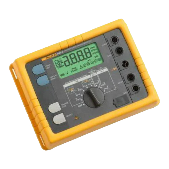
Introduction The 1625-2 Earth Ground Tester (Tester or Product) is a compact, field-rugged instrument that performs all four types of earth ground measurement. Specifically, the Tester is able to measure earth ground loop resistances using only clamps – called Stakeless testing. This method doesn’t require the use of earth ground stakes or the disconnection of ground rods. -
Page 10: How To Contact Fluke
Users Manual The effectiveness of grounding systems should be checked using a earth/ground tester such as the 1625-2 which checks the effectiveness of connections to the ground. The 1625-2 provides the perfect solution by combining the latest technology into a compact, field-rugged instrument. -
Page 11: Safety Information
Earth/Ground Tester Safety Information Safety Information A Warning identifies hazardous conditions and procedures that are dangerous to the user. A Caution identifies conditions and procedures that can cause damage to the Product or the equipment under test. Warning To prevent possible electrical shock, fire, or personal injury: •... -
Page 12: Storage
9 "Monitoring and Control Instrumentation” product. Do not dispose of this product as unsorted municipal waste. Go to Fluke’s website for recycling information. Storage If the Tester is stored for an extended period of time or is not in use for a long time, you... -
Page 13: Models And Accessories
(Includes Users Manual, Safety Information, QRG, Geox Probe Cable, 2 clips, Lead set) 4325162 1625-2 Kit Earth Ground Tester Kit (Includes Users Manual, Safety Information, QRG, Geox Probe Cable, 2 clips, Lead set, 4 Earth Stakes, 3 Cable Reels, C1620 Carrying Case, EI-... -
Page 14: Additional Accessories
1625-2 Users Manual Additional Accessories An external current transformer is available as an option, see Figure 1. The transformer has a transformation ratio between 80 and 1200:1 for the measurement of a single branch in mesh-operated earthing systems. This enables the user to measure on high voltage pylons without separating the overhead earth wires or earth strips at the bottom of the pylons. -
Page 15: Features
Earth/Ground Tester Features Features The 1625-2 Earth/Ground Tester (Tester) is an earth resistance meter with fully automated measuring frequency selection process. The Tester includes automatic testing of probe and auxiliary earth electrode resistances and possible interference voltages in accordance with DIN IEC61557-5/EN61557-5: •... - Page 16 1625-2 Users Manual Table 3. Features and Functions Rear Side edw006.eps Description Rotary switch to select measurement function and ON/OFF "START TEST" button to start the selected measurement function "DISPLAY MENU" button to select the setting or show test data ...
-
Page 17: Display
Earth/Ground Tester Display Display The display is a 4-digit (2999 Digit), 7 segment liquid crystal display (Table 4). Table 4. Display Elements edw004.eps Item Description Test Type Interference voltage (AC + DC) Frequency of interference voltage Frequency of measuring voltage Measuring voltage limit 20/48 V Earthing resistance ... - Page 18 1625-2 Users Manual Table 5 shows what you will see on the display as you operate the Tester. Table 5. Display Descriptions Function Displays Condition Note Before Stand by position to Turn rotary switch or START reduce power push button. All...
- Page 19 Earth/Ground Tester Display Table 5. Display Descriptions (cont.) Function Displays Condition Note Aux. current spike- Wait for test result. resistance is being tested. edw035.eps Earth resistance is Wait for test result. being tested. edw036.eps Measuring circuit of Check lead connection earth and on earth spikes auxiliary-earth...
- Page 20 1625-2 Users Manual Table 5. Display Descriptions (cont.) Function Displays Condition Note Compensation higher Delete compensation than measured value. or switch instrument ON/OFF. edw042.eps Wrong polarity on Reverse polarity. jacks E and ES. edw043.eps Measured value Unsteady noise unstable. voltage. Try time average measurement.
-
Page 21: Setup
Earth/Ground Tester Setup Table 5. Display Descriptions (cont.) Function Displays Condition Note Hardware malfunction Switch ON/OFF if still (for example, current faulty. overload). The symbol may appear when using the stakeless measurement on low edw049.eps resistance circuits. EE PROM memory Contact service. - Page 22 1625-2 Users Manual 1625B EARTH / GROUND TESTER edw070.eps Figure 2. Battery Insertion Warning To prevent possible electrical shock, fire, or personal injury: • The battery door must be closed and locked before you operate the Product. • Replace the batteries when the low battery indicator shows to prevent incorrect measurements.
-
Page 23: Description Of Functions
Earth/Ground Tester Setup Description of Functions The functions are selected with the central rotary switch. Four push buttons start measurements, read out supplementary measurement values, and select special functions. See Table 6 for more information. Measurement values are shown on a liquid crystal display with units. Additional special characters indicate measurement mode, operating condition and error messages. -
Page 24: Operation
1625-2 Users Manual Operation Warning To prevent possible electrical shock, fire, or personal injury, use the instrument on voltage free systems only. 1. Set measuring function with the central rotary switch. 2. Connect the measurement leads to the instrument. -
Page 25: Control Loop
Earth/Ground Tester Advanced Operation c) Prolonged display test By keeping the "DISPLAY MENU" button pressed during power on, the display test can be prolonged for any length of time. Return to the standard operation mode by pressing any button or turning of the central rotary switch. d) Number of software version By keeping the "SELECT"... - Page 26 1625-2 Users Manual Depending on the selected function, the parameters can be shown or changed. See Table 6. Table 6. Control Loop Parameters Function Parameter Setting Range Remarks U ST display only F ST display only R E 3-pole (AFC/94/105/111/128) Hz...
-
Page 27: Measurement Loop
Earth/Ground Tester Advanced Operation Measurement Loop This loop is entered by pressing the "START TEST" button. After releasing "START TEST" the last measured value stays on the display. By repeated pressing of the "DISPLAY MENU" button all supplementary values can be called. If a measured value exceeds or falls below the pre-set limit, the limit can be displayed as well (with "DISPLAY MENU"). -
Page 28: Earthing Resistances Measurement
1625-2 Users Manual Earthing Resistances Measurement This instrument is equipped with a 3-pole as well as a 4-pole resistance measurement that renders measurements of resistances of earthing systems possible, as well as measurements of the soil resistivity of geological strata. A specific description of the different applications is given further on in this manual. -
Page 29: 3-Pole/4-Pole Measurement Of Earthing Resistance
Earth/Ground Tester Advanced Operation 3-Pole/4-Pole Measurement of Earthing Resistance This measuring function measures earthing and earth dissipation resistances of single earth electrodes, foundation earth electrodes and other earthing systems by using two earth spikes. See Figure 4. 4 Pole Auxiliary earth electrode Probe... - Page 30 1625-2 Users Manual Remarks for the setting of earth spikes: Before setting the earth spikes for probe and auxiliary earth electrode make sure that the probe is set outside the potential gradient area of earth electrode and auxiliary earth electrode. Such a condition is normally reached by allowing a distance of >20 m between the earth electrode and the earth spikes as well as of the earth spikes to each other.
-
Page 31: Measurement Of Single Earth Electrode Resistances In Mesh Operated Earthing Systems Using Selective Clamp Method
Earth/Ground Tester Advanced Operation Measurement of Single Earth Electrode Resistances in Mesh Operated Earthing Systems Using Selective Clamp Method This measuring method has been created to measure single earth electrodes in permanently wired or mesh-operated systems (for example, a lightning protection system with several electrodes or high voltage pylons with earth cabling). -
Page 32: 3-Pole/4-Pole Measurement Of Single Earth Electrode Resistances
1625-2 Users Manual 3-Pole/4-Pole Measurement of Single Earth Electrode Resistances Turn central rotary switch to position " RE 3pole" or " RE 4pole". The instrument is to be wired according to Figure 6 and messages on the display. 4 Probe... - Page 33 Earth/Ground Tester Advanced Operation Press "START TEST" button. Now a fully automated test sequence of all relevant parameters like auxiliary earth electrode and probe and earth electrode resistance is implemented and finished with the display of the result R 1. Read out measured value R 2.
-
Page 34: Measurements On High Voltage Pylons
1625-2 Users Manual Measurements on High Voltage Pylons Measuring the Earthing Resistance without Disengaging the Overhead Earth Wire Using the Selective Clamp Method The measurement of the earth resistance of a single high voltage pylon usually requires the overhead earth wire to be disengaged (lifted off) or the separation of the earthing system from the pylon construction. - Page 35 Earth/Ground Tester Advanced Operation As all four pylon stubs are connected to the foundation earth of the pylon, the measuring current I is divided into five components according to the present resistances meas involved. One part flows via pylon construction to the overhead earth wire and further to the parallel circuited pylon earthing resistances.
- Page 36 1625-2 Users Manual Notices for the setting of earth spikes: Before setting the earth spikes for probe and auxiliary earth electrodes make sure that the probe is set outside the potential gradient of earth electrode and auxiliary earth electrode. Such a condition is normally reached by allowing a distance of >20 m between the earth electrode and the earth spikes as well as to the earth spikes to each other.
-
Page 37: Clip-On Transformer Errors Correction
Earth/Ground Tester Advanced Operation Measuring Earthing Impedance with 55 Hz (R*) For the calculation of short circuit currents in power supply plants, the complex earthing impedance is important. Direct measurement is possible under the following conditions: 30 °... 60 ° inductive Phase angle at 50 Hz: Auxiliary earth electrode (ohmic): >100 •... - Page 38 1625-2 Users Manual 3. Press "START TEST"-button and note result of R value. 4. Connect clip-on transformer. See Figure 9. edw018.eps Figure 9. Clip-on Transformer Connection 5. Turn central rotary switch to position " RE 3pole". 6. Press "START TEST" again.
-
Page 39: Compensation Of Earth Electrode Connecting Lead
Earth/Ground Tester Advanced Operation Compensation of Earth Electrode Connecting Lead If the line resistance to the earth electrode cannot be ignored, a compensation of the connecting lead resistance to the earth electrode is possible. Measuring process: Auxiliary earth Earth electrode electrode edw019.eps Figure 10. -
Page 40: Measurement Of Soil Resistivity
1625-2 Users Manual Measurement of Soil Resistivity The soil resistivity is the geological and physical quantity for calculation and design of earthing systems. The measuring procedure shown in Figure 11 uses the method developed by Wenner (F. Wenner, A method of measuring earth resistivity; Bull. National Bureau of Standards, Bulletin 12 (4), Paper 258, S 478-496;... - Page 41 Earth/Ground Tester Advanced Operation 4. Read out measured value R From the indicated resistance value R , the soil resistivity calculates according to the equation: ρ π a. . ρ ..mean value of soil resistivity (Ωm) ..measured resistance (Ω) ..
-
Page 42: Measurement Of Resistances
1625-2 Users Manual With increasing depth ρE is not decreasing: a strip conductor electrode is Curve 3: advisable. As measuring results are often distorted and corrupted, for example, by underground pieces of metal and underground aquifers, a second measurement, in which the spike axis is turned by an angle of 90 °, is always advisable (see graph below). -
Page 43: Resistance Measurement (R)
Earth/Ground Tester Advanced Operation 3. In this mode, all settings and LIMIT values available can be called with "DISPLAY MENU" and the measuring frequency can be set. 4. Press "START TEST" button. 5. Read out measured value. Resistance Measurement (R) In this measuring mode all resistances from 0.02 Ω... -
Page 44: Compensation Of Measuring Lead Resistance
1625-2 Users Manual 4. Start measurement with "START TEST" button. First, "R1" with positive voltage is measured on jack "E". After releasing the "START TEST" button "R " is measured with negative voltage on jack "E". The respectively higher measured value is displayed first. -
Page 45: How To Change All Data Settings With Personalized Code
Earth/Ground Tester Advanced Operation How to Change All Data Settings with Personalized CODE With this function (FM, UM-Limit, Limit, beeper, ratio, R*) limit and set values can be programmed which keeps them in memory even if the instrument is switched ON/OFF. This feature enables the operator to create an instrument setup with customer defined settings according to the specific need. - Page 46 1625-2 Users Manual To save a code: 1. Press all 4 keys simultaneously and move central selector from OFF to the desired measuring mode. The display shows "C _ _ _". 2. Now enter the CODE number. Any three-digit number can be entered.
-
Page 47: Export Stored Data To Pc
Earth/Ground Tester Export Stored Data to PC 4. Display shows "C ON". In the "C ON" state the CODE function can be disabled by pressing the "CHANGE ITEM" key. The display then shows "C OFF". 5. If this display is acknowledged by pressing the "DISPLAY MENU" key, the user code and all changes of the limit values are erased. -
Page 48: Delete Stored Data
1625-2 Users Manual Table 8. Sample .CSV File for Logged Data (cont.) 1.022 Ω 0.0 Hz 1.02 Ω 1.022 Ω 0.0 Hz 1.02 Ω 1.022 Ω 100.0 Hz 0.0A 1006 Ω 0.0 Hz 0.0A 1.022 Ω 100.0 Hz 1.023 Ω... -
Page 49: Maintenance
If the meter still fails to operate properly, pack securely (in its original container if available) and forward it, postage paid, to the nearest Fluke Service Center. Include a brief description of the problem. Fluke assumes NO responsibility for damage in transit. -
Page 50: Specifications
1625-2 Users Manual Specifications Temperature Range Operating: 0 °C to +35 °C (+32 °F to +95 °F) Storage: -30 °C to +60 °C (-22 °F to +140 °F) Temperature coefficient: ±0.1 % of rdg / °C (below 18 °C and above 28 °C) Operating humidity: <95% RH non-condensing... - Page 51 Earth/Ground Tester Specifications Interference Frequency (F ) Measurement Measuring method: Measurement of oscillation period of the interference voltage Measuring Display Range Resolution Range Accuracy Range 16.0 … 400 Hz 16.0…299.9…999 Hz 0.1 … 1 Hz 1 V … 50 V ±(1% rdg +2 digit) Earthing Resistance (R Measuring method:...
- Page 52 1625-2 Users Manual Measuring Display Range Resolution Accuracy Operating Error Range 0.001 Ω...2.999 Ω 0.001 Ω 3.00 Ω...29.99 Ω 0.01 Ω 30.0 Ω…299.9 Ω 0.1 Ω ± (2 % of rdg +2 digit) ± (5% of rdg +5 digit) 0.020 Ω…300 kΩ...
- Page 53 Earth/Ground Tester Specifications Selective Measurement of the Earthing Resistance (R ) Measuring method: Current and voltage measurement with probe as per EN61557-5 and current measurement in the individual branch with additional current transformer. Open circuit voltage: 20 / 48 V ac Short circuit current: 250 mA ac Measuring frequency:...
- Page 54 1625-2 Users Manual Resistance Measurement (R Measuring method: current and voltage measurement Measuring voltage: 20 V ac, square pulse Short circuit current: >250 mA ac Measuring frequency: 94, 105, 111, 128 Hz selected manually or automatically (AFC) Measuring Range Display Range...
- Page 55 Earth/Ground Tester Specifications Measuring sequence: approximately 2 measurements/s Measuring time: typical 4 seconds includes reversal of polarity (2-pole or 4-pole) Maximum interference voltage: ≤3 V ac or dc, with higher voltages measurement will not be started Maximum inductivity: 2 Henry Maximum overload: = 250 V Compensation of Lead Resistance (R...
- Page 56 1625-2 Users Manual...