
Related Manuals for Fujitsu PRIMERGY BX920 S2


Summary of Contents for Fujitsu PRIMERGY BX920 S2
-
Page 1: Server Blade
Operating Manual - English PRIMERGY BX920 S2 Server Blade Operating Manual May 2010... -
Page 2: Copyright And Trademarks
Gesellschaft für Technik-Dokumentation mbH www.cognitas.de Copyright and Trademarks Copyright © 2010 Fujitsu Technology Solutions GmbH. All rights reserved. Delivery subject to availability; right of technical modifications reserved. All hardware and software names used are trade names and/or trademarks of their respective... - Page 3 Before reading this manual For your safety This manual contains important information for safely and correctly using this product. Carefully read the manual before using this product. Pay particular attention to the accompanying manual "Safety notes and other important information" and ensure these safety notes are understood before using the product.
- Page 4 (hereafter, "high safety use"). Customers should not use this product for high safety use unless measures are in place for ensuring the level of safety demanded of such use. Please consult the sales staff of Fujitsu if intending to use this product for high safety use.
- Page 5 Only for the Japanese market: Although described in this manual, some sections do not apply to the Japanese market. These options and routines include: – USB Flash Module (UFM) – CSS (Customer Self Service) – Conversion of standard power supply to hot-plug power supply –...
- Page 6 Operating Manual BX920 S2...
-
Page 7: Table Of Contents
Contents Introduction ......7 Concept and target groups for this manual ..7 Documentation overview . - Page 8 Contents Switching the Server Blade on and off ... . . 44 Configuring the Server Blade ....45 5.3.1 Preparing for local installation .
- Page 9 Contents Property and data protection ....81 BIOS Setup security functions ....81 Troubleshooting and tips .
- Page 10 Contents Operating Manual BX920 S2...
-
Page 11: Introduction
If you no longer have the ServerView Suite DVDs, you can obtain the relevant current versions using the order number U15000-C289 (the order number for the Japanese market: please refer to the configurator of the server http://primeserver.fujitsu.com/primergy/system.html). Operating Manual BX920 S2... - Page 12 Industry standard servers navigation option. For the Japanese market please use the URL: http://primeserver.fujitsu.com/primergy/manual.html. More information on your PRIMERGY BX920 S2 can be found in the following documents: – "Quick Start Software - Quick Installation Guide" DVD booklet...
-
Page 13: Performance Features
Concept - LSC" manual on the ServerView Suite DVD 2). In addition, CSS errors are displayed in the ServerView Operations Manager, the server management software from Fujitsu. In the event of errors, the ServerView Operations Manager refers you directly to the affected component and its order information in the Illustrated Spares catalog of the server in question. - Page 14 Performance features System board The features of the system board are described in the technical manual for the system board D3030 for the hardware and in the BIOS Setup chapter of this manual for the firmware. Trusted Platform Module (TPM) A Trusted Platform Module (TPM) for safer storage of keys can be implemented as an option.
- Page 15 Performance features If a server blade is configured with one or two mezzanine cards, this does not exclude other configurations for any of the other server blades in a BX900 system unit. If you want to install mezzanine cards in server blades, the system unit must be equipped with the corresponding fiber-channel, Infiniband and/or Ethernet connection blades.
- Page 16 ASR&R (Automatic Server Reconfiguration and Restart) restarts the system in the event of an error and automatically "hides" the defective system components. The PDA (Prefailure Detection and Analyzing) technology from Fujitsu Technology Solutions analyzes and monitors all components that are critical for system reliability.
- Page 17 Performance features Full-coverage alarm management System Event Log (SEL) reading and processing More information about the iRMC S2 can be found in the "iRMC S2 - integrated Remote Management Controller" user’s guide (on the ServerView Suite DVD 2 under Industry Standard Servers - Software - ServerView Suite - Out-Of-Band Management).
-
Page 18: Notational Conventions
Notational conventions Service and support PRIMERGY servers are service-friendly and modular, thus enabling quick and simple maintenance. The flash EPROM program supplied with the FSC utilities supports fast BIOS update via the USBinterface. The two redundant hot-pluggable management blades of the PRIMERGY BX900 system unit, with independent LAN and COM connectors for management, enable comprehensive remote administration for the server blade. -
Page 19: Technical Data
Technical data Technical data Electrical specifications Power consumption 350 W (full configuration) Thermal dissipation 1260 kJ/h Compliance with regulations and standards Product safety and IEC 60950-1 / EN 60950-1, UL/CSA 60950-1, CNS 14336 / GB 4943 / EN 50371 ergonomics Electromagnetic FCC class A compatibility... - Page 20 Technical data Certification Product safety approved with the PRIMERGY BX900 basic system Global Germany GS, CE USA/Canada /CSA Japan VCCI China/Taiwan BSMI Mechanical specifications Width 45 mm Depth 508 mm Height 210,5 mm (1 bay in the system unit) Weight Max.
-
Page 21: Overview: Installation Steps
Overview: Installation steps This chapter contains an overview of the steps necessary to install your Server Blade. The cross-references take you to the sections containing more detailed information on the relevant installation step: Ê First read the chapter "Important notes" from page 19, particularly the... - Page 22 – Local installation with or without ServerStart/Installation Manager Local installation is the least convenient method. It is only recommended if the requirements for remote installation and cloning are not met. If you want to install an operating system that is not supported by ServerStart, you can of course install it directly without ServerStart.
-
Page 23: Important Notes
Important notes This chapter provides safety instructions which you must observe when handling your server. Safety instructions The following safety instructions are also provided in the manual "Safety notes and other important information". This device meets the relevant safety regulations for IT equipment. If you have any questions about whether you can install the server in the intended environment, please contact your sales outlet or our customer service team. - Page 24 Safety instructions Before starting up CAUTION! During installation and before operating the device, observe the instructions on environmental conditions for your device (see "Ambient conditions" on page 16). If the server has been moved from a cold environment, condensation may form both inside and on the outside of the machine. Wait until the server has acclimatized to room temperature and is absolutely dry before starting it up.
- Page 25 Safety instructions CAUTION! In emergencies (e.g. damaged casing, control elements or power cable, penetration of liquids or foreign bodies), switch off the device immediately, unplug it from the grounded power outlets, and contact your customer service center. Proper operation of the device (in accordance with IEC 60950-1/EN 60950-1) is only ensured if the casing is fully assembled and the rear covers for the installation bays are in place (electric shock, cooling, fire protection, interference suppression).
- Page 26 Safety instructions Batteries CAUTION! Incorrect replacement of batteries may lead to a risk of explosion. The batteries may only be replaced with identical batteries or with a type recommended by the manufacturer (see the technical manual for the system board). Do not throw batteries into the trash can.
- Page 27 Safety instructions Working with CDs/DVDs/BDs and optical drives When working with devices with optical drives, these instructions must be followed. CAUTION! Only use CDs/DVDs/BDs that are in perfect condition, in order to prevent data loss, equipment damage and injury. Check each CD/DVD/BD for damage, cracks, breakages etc. before inserting it in the drive.
- Page 28 Safety instructions Do not contaminate the CD/DVD/BD surface with fingerprints, oil, dust, etc. If dirty, clean with a soft, dry cloth, wiping from the center to the edge. Do not use benzene, thinners, water, record sprays, antistatic agents, or silicone-impregnated cloth. Be careful not to damage the CD/DVD/BD surface.
- Page 29 Safety instructions Modules with Electrostatic-Sensitive Devices Modules with electrostatic-sensitive devices are identified by the following sticker: Figure 1: ESD label When you handle components fitted with ESDs, you must always observe the following points: Switch off the system and remove the power plugs from the power outlets before installing or removing components with ESDs.
-
Page 30: Ce Conformity
CE conformity Other important information: During cleaning, observe the instructions in section "Cleaning the Server Blade" on page Keep this operating manual and the other documentation (such as the technical manual, documentation DVD) close to the device. All documentation must be included if the equipment is passed on to a third party. -
Page 31: Notes On Installation In The System Unit
Notes on installation in the system unit Notes on installation in the system unit CAUTION! Beware of the energy hazard at the midplane contacts of the system unit. A short circuit on these contacts may damage the system. Operating Manual BX920 S2... -
Page 32: Environmental Protection
Environmental protection Environmental protection Environmentally-friendly product design and development This product has been designed in accordance with the Fujitsu standard for "environmentally friendly product design and development". This means that key factors such as durability, selection and labeling of materials, emissions, packaging, ease of dismantling and recycling have been taken into account. - Page 33 Details regarding the return and recycling of devices and consumables within Europe can also be found in the "Returning used devices" manual, via your local Fujitsu branch or from our recycling center in Paderborn: Fujitsu Technology Solutions Recycling Center D-33106 Paderborn Tel.
- Page 34 Environmental protection Operating Manual BX920 S2...
-
Page 35: Installing The Hardware
Installing the hardware CAUTION! Follow the safety instructions in the chapter "Important notes" on page Do not expose the server to extreme environmental conditions (see "Ambient conditions" on page 16). Protect the server from dust, humidity and heat. Make sure that the server is acclimatized for the time indicated in this table before putting it into operation. -
Page 36: Unpacking The Server
Unpacking the server Unpacking the server CAUTION! Follow the safety instructions in chapter "Important notes" on page The server must always be lifted or carried by at least two people. (For the Japanese market, please refer to " 安全上の注意およびその他の 重要情報 ".) Do not unpack the server until it is at its installation location. - Page 37 Installing the Server Blade in the system unit Removing the dummy module Any unused slots on the front of the system unit are fitted with appropriate dummy modules to comply with electromagnetic compatibility (EMC) regulations and to ensure sufficient cooling of the system components. To add a server blade, you must first remove a dummy module from the relevant slot.
- Page 38 Installing the Server Blade in the system unit Installing the dummy module To install the dummy module, follow the same procedure as for removing it, except in reverse order. Installing the Server Blade CAUTION! Follow the safety instructions and information in section "Modules with Electrostatic-Sensitive Devices"...
- Page 39 Installing the Server Blade in the system unit Figure 4: Locking the Server Blade Ê Pull the release lever up until it engages. You remove the connection blade by performing the above procedure in reverse. CAUTION! If you remove a server blade and do not replace it with a new one, you must install a dummy module to comply with the regulations regarding electromagnetic compatibility and to ensure sufficient cooling of the system components.
-
Page 40: Connecting Devices
Connecting devices Connecting devices All connections that are required to operate the server blade are made via the midplane of the PRIMERGY BX900 system unit. When the server blade is installed, midplane contacts automatically establish connections to the infrastructure modules on the rear of the system unit: –... -
Page 41: Instructions For Connecting/Disconnecting Cables
Instructions for connecting/disconnecting cables Instructions for connecting/disconnecting cables CAUTION! Be sure to read the documentation for the peripheral devices before connecting them. Do not connect or disconnect data cables during a thunderstorm. When removing a cable, always hold it by the plug. Never unplug a cable by pulling at the cable itself. - Page 42 Instructions for connecting/disconnecting cables Operating Manual BX920 S2...
-
Page 43: Installation And Operation
Installation and operation CAUTION! Follow the safety instructions in chapter "Important notes" on page Control and display elements Figure 6: Control and display elements I/O indicator: fabric 1 Global Error indicator I/O indicator: fabric 2 ID button with ID indicator I/O indicator: fabric 3/4 On/Off button with power-on indicator CSS indicator... - Page 44 Control and display elements Control elements On/Off button When the system is switched off, it can be switched on again by pressing the On/Off button. When the system is operating, pressing the On/Off button will switch off the system. CAUTION! Risk of loss of data! The On/Off button does not disconnect the server from the mains voltage.
- Page 45 Control and display elements Global Error indicator (orange) – Lights up orange if a prefailure event has been detected that requires (precautionary) service intervention. – Flashes orange if an error was detected that requires service intervention. – Does not light up if there is no critical event. If the event is still acute after a power failure, the indicator is activated after the restart.
- Page 46 Control and display elements Status indicators for the I/O fabrics* (green) – Lights up to indicate a network connection. – Flashes to indicate an active network connection. – Does not light up if there is no network connection. * The three I/O fabrics of the server blade are: Fabric 1: onboard LAN controller Fabric 2: mezzanine card 1 Fabric 3/4: mezzanine card 2...
- Page 47 Control and display elements HDD FAULT (orange) (in conjunction with a RAID controller) – Does not light: no HDD error – Lights up: HDD Faulty or Rebuild Stopped (drive defective, needs replacing, a rebuild process was stopped or the HDD module is not correctly inserted) –...
-
Page 48: Switching The Server Blade On And Off
Switching the Server Blade on and off Switching the Server Blade on and off CAUTION! If you switch the server blade on and flickering stripes appear on the connected monitor, switch the server blade off again immediately (see chapter "Troubleshooting and tips" on page 83). -
Page 49: Configuring The Server Blade
Configuring the Server Blade Configuring the Server Blade This section contains information about configuring the server blade and installing the operating system. The operating system can be installed in various ways: – Local installation with or without the ServerView Installation Manager You can find information on local installation in the following sections. -
Page 50: Configuring Sas Raid Controller
Configuring the Server Blade 5.3.2 Configuring SAS RAID controller The server blade has a SAS RAID controller with "Integrated Mirroring Enhanced" functionality or "MegaRAID functionality". You can configure the SAS RAID controller either before or during installation with the ServerView Installation Manager. -
Page 51: Configuring The Server And Installing The Operating System Without Serverview Installation Manager
Configuring the Server Blade – Wizard-assisted creation of configuration files for unattended installation of several PRIMERGY servers with identical hardware configurations. – Installation of drivers and additional software. The software that can be installed depends on your server’s hardware configuration. This configuration is detected automatically. Descriptions of operating systems not covered in the RAID controller manual are provided in the corresponding readme files on the driver CDs. -
Page 52: Cleaning The Server Blade
Cleaning the Server Blade Cleaning the Server Blade CAUTION! Switch off the server blade and remove it from the system unit (see page 34). Do not clean any interior parts of the server blade yourself; leave this job to a service technician. Do not use abrasive powder or detergents which dissolve plastic to clean the housing exterior. -
Page 53: Bios Setup
BIOS Setup You can set the system functions and the hardware configuration of a server blade in the BIOS Setup. The range of BIOS parameters displayed can vary according to the configuration. The default settings are effective when the server blade is delivered. You can change these settings in the BIOS Setup. - Page 54 Advanced – Advanced Settings (continued) USB Devices [ 60] USB Front [ 60] LAN Controller n [ 61] Port n Remote Boot [ 61] Mezzanine Card 1: Type [ 62] Port n Remote Boot [ 62] Mezzanine Card 2: Type [ 63] Port n Remote Boot [ 63] Advanced System Configuration [ 60] High Precision Event Timer [ 64]...
- Page 55 Security – Security Settings Supervisor Password / User Password [ 67] Set Supervisor Password [ 67] Supervisor Password Lock [ 67] Set User Password [ 68] Password on Boot [ 68] Flash Write [ 68] TPM (Security Chip) [ 68] Current TPM State [ 68] Security Chip [ 68] Change TPM State [ 69]...
- Page 56 Server – Server Configuration (continued) Protocol [ 75] Flow Control [ 76] Continue C.R. after POST [ 76] IPMI [ 73] SM Error Halt [ 76] Load iRMC Default Values [ 76] Event Log Full Mode [ 77] SDRR Version [ 77] LAN Settings [ 77] Service LAN [ 77] Service LAN Port [ 77]...
-
Page 57: Access
Access Access Ê Start the server blade in cold boot or warm boot mode. Ê Press the function key [F2]. Ê Enter the Setup password (if assigned) and confirm your entry by pressing the Return key. Operation The BIOS Setup screen is structured as follows: Figure 8: "Main"... - Page 58 Operation Workspace The information for the selected menu is displayed and settings are provided in the workspace (on the left of the screen). You select the required menu item using the arrow keys Ê and Ë. A Ê at the left edge of the screen indicates a menu item that contains further submenus.
-
Page 59: Sysinfo Menu
SysInfo menu SysInfo menu Figure 9: "SysInfo" BIOS Setup menu, page 1 System Information, Page 1 Displays information concerning the BIOS, CPU and various IDs. Operating Manual BX920 S2... - Page 60 SysInfo menu Figure 10: "SysInfo" BIOS Setup menu, page 2 System Information, Page 2 Displays information on LAN MAC addresses (including the LAN MAC address of the iRMC) and COM ports. Operating Manual BX920 S2...
-
Page 61: Main Menu
Main menu Main menu Figure 11: "Main" BIOS Setup menu System Time / System Date Sets the system time and the system date. The system time format is HH:MM:SS. The system date format is WeekdayMM/DD/YYYY. By pressing [Ú], [Tab] or [Í]+[Tab] you can position the cursor within the relevant input field and configure the values using [+] or [-]. -
Page 62: Boot Features Menu
Main menu Boot Features Calls a submenu with the options during the boot process (see page 58). System Memory / Extended Memory Shows the size of the available main memory. 6.4.1 Boot Features menu POST Errors Specifies whether the system will be stopped (Enabled) or not (Disabled) if an error occurs during the boot process. -
Page 63: Advanced Menu
Advanced menu Advanced menu Figure 12: "Advanced" BIOS Setup menu Reset Configuration Data Specifies whether the configuration data is reinitialized when the server blade is started. Once the server blade is started, the plug&play functionality determines the new configuration data and initializes the installed boards and drives with this. -
Page 64: Peripheral Configuration
Advanced menu Advanced System Configuration Calls a submenu for configuring the PCI slots and PCI components on the motherboard (see page 64). Advanced Memory Options Calls a submenu for specifying the memory properties (see page 64). Advanced Processor Options Calls a submenu for specifying the CPU properties (see page 65). - Page 65 Advanced menu LAN Controller n Specifies (for each controller) whether a port is activated by onboard LAN Controller n, and if so, which port. Disabled No port is activated. Port 1 PORT 1 is activated. Port 1 & 2 Both ports are activated. Port n Remote Boot Specifies whether onboard LAN n OPROM is active during the POST.
- Page 66 Advanced menu Mezzanine Card 1: Type Shows the mezzanine card type installed in mezzanine card slot 1. Empty No mezzanine card is installed. LAN mezzanine card is installed. Fibre Channel Fibre channel mezzanine card is installed. iSCSI iSCSI mezzanine card is installed. Others Another type of mezzanine card is installed.
- Page 67 Advanced menu Mezzanine Card 2: Type Shows the mezzanine card type configured in mezzanine card slot 2. Empty No mezzanine card is installed. LAN mezzanine card is installed. Fibre Channel Fibre channel mezzanine card is installed. iSCSI iSCSI mezzanine card is installed. Others Another type of mezzanine card is installed.
-
Page 68: Advanced System Configuration
Advanced menu 6.5.2 Advanced System Configuration The "Advanced System Configuration" submenu contains the following items: High Precision Event Timer Specifies whether the High Precision Event Timer for time-critical applications (e.g. multimedia applications) is activated (Enabled) or deactivated (Disabled). I/OAT ® Specifies whether the advanced hardware capabilities of Intel Acceleration Technology (I/OAT) is activated (Enabled) or deactivated (Disabled). -
Page 69: Advanced Processor Options
Advanced menu SMBIOS T17 Inactive Specifies whether DIMM sockets are set to Inactive in SMBIOS when not available (Enabled) or not (Disabled). 6.5.4 Advanced Processor Options You can specify the CPU properties using the menu items in this submenu. CPU Mismatch Detection Specifies whether the system checks for identical processors (Enabled) or not (Disabled) during the POST. - Page 70 Advanced menu Virtualization Tech (VT-x) Specifies whether additional hardware properties (Vanderpool Technology) are activated (Enabled) or deactivated (Disabled). A complete reset is necessary to change this option. Virtualization Tech (VT-d) Specifies whether additional hardware properties (Virtualization Technology for Directed I/O) are activated (Enabled) or deactivated (Disabled).
-
Page 71: Security Menu
Security menu Security menu Figure 13: "Security" BIOS Setup menu Supervisor Password / User Password Shows whether the corresponding password has been assigned (Installed) or not (Not Installed). Set Supervisor Password Used for setting up or changing a user's password. To delete a supervisor password, open the window for assigning passwords and press Return twice. -
Page 72: Tpm (Security Chip)
Security menu Set User Password Used for setting up or changing a user's password. Password on Boot Enables password entry on boot (Enabled) or not (Disabled). Flash Write Specifies whether the BIOS flash memory is write-protected (Enabled) or not (Disabled). TPM (Security Chip) Calls a submenu for specifying additional settings for TPM (see page... - Page 73 Security menu Change TPM State This item will only be displayed when Security Chip is set to Enabled and is enabled actually. A reboot is required after exit to configure Security Chip correctly. This field enables you to modify the status of the Trusted Platform Module using the BIOS.
-
Page 74: Power Menu
Power menu Power menu Figure 14: "Power" BIOS Setup menu Power-on Source Specifies whether power-on sources for ACPI operating systems are controlled by the BIOS or by the operating system. BIOS Controlled Power-on sources are controlled by the BIOS. Switching on via LAN or timer is permitted. - Page 75 Power menu Power Failure Recovery Specifies how the system behaves during recovery after a power failure. Always Off Switches the system off. Always On Switches the system on. Previous State Switches to the state the system was in before the power failure. Operating Manual BX920 S2...
-
Page 76: Server Menu
Server menu Server menu Figure 15: "Server" BIOS Setup menu O/S Boot Timeout Specifies whether a reset is performed (Enabled) or not (Disabled) after a specified timeout if the operating system could not be started. Action Sets the action for a timeout of the operating system boot watchdog timer. - Page 77 Server menu This item is only displayed if "O/S Boot Timeout" is set to Enabled. Timeout Value Sets the boot watchdog timer of the operating system in minutes (0 ... 100). This item is only displayed if "O/S Boot Timeout" is set to Enabled.
-
Page 78: Cpu Status
Server menu 6.8.1 CPU STATUS CPU 1 Status / CPU 2 Status Specifies the status of the installed CPUs. The status of an unpopulated CPU socket cannot be changed. Enabled The service processor stops the CPU upon request. Disabled The function is not activated. Failed The service processor stops the CPU due to an error. -
Page 79: Pci Status
Server menu 6.8.3 PCI Status Shows the current status of the PCI adapters in the slots. Slot x No errors were reported for this slot. The PCI adapter in this slot can be used without restriction. Failed An error was detected for this slot. The PCI adapter in this slot may have a problem. -
Page 80: Ipmi
Server menu Flow Control Specifies how the transfer is controlled via the port. The setting (None, XON/XOFF) must be the same at both the terminal and server. This item is only hidden if "Port" is set to Disabled. Continue C.R. after POST Specifies whether communication with the terminal is also possible whilst the operating system is being loaded (On) or not (Off). -
Page 81: Lan Settings
Server menu Event Log Full Mode Specifies the Event Logging mode. Maintain Event Logging is stopped as soon as the SEL (System Event Log) is full. Overwrite Event Logging continues despite the SEL being full. The oldest entry is overwritten. SDRR Version Shows the SDRR version number. -
Page 82: Ipmi Settings
Server menu Local IP Address Entry for configuring the IP address (000.000.000.000). This item is only hidden if "Service LAN" is set to Disabled. It is grayed out if "DHCP" is set to Enabled. It can be set if "DHCP" is set to Disabled. -
Page 83: Boot Menu
Boot menu Boot menu Figure 16: "Boot" BIOS Setup menu 1st Boot Device / 2nd Boot Device / 3rd Boot Device / 4th Boot Device / 5th Boot Device Specifies the order in which the available devices are accessed during the boot process. -
Page 84: Exit Menu
Exit menu 6.10 Exit menu Figure 17: "Exit" BIOS Setup menu Save Changes and Exit Saves all parameter changes of the current session and exits the BIOS Setup. Discard Changes and Exit Discards all parameter changes of the current session and exits the BIOS Setup. -
Page 85: Property And Data Protection
Property and data protection The lockable rack door protects the server against unauthorized access. To protect the system and data internally against unauthorized access, you can activate the security functions of the BIOSSetup. BIOS Setup security functions The Security menu in the BIOS Setup provides you with various options for protecting your data from unauthorized access. - Page 86 BIOS Setup security functions Protecting BIOS from being overwritten To activate this protection, select the value Disabled for the Flash Write field in the Security menu. Protecting the server from being switched on by an external device To activate this protection, select the value Disabled for the Remote Power On field in the Security menu.
-
Page 87: Troubleshooting And Tips
Troubleshooting and tips CAUTION! Follow the safety instructions in the "Safety notes and other important information" manual and in chapter "Important notes" on page If a fault occurs, attempt to resolve it using the measures described: – in this chapter, –... -
Page 88: Flickering Stripes On Monitor Screen
Flickering stripes on monitor screen Screen has gone blank Ê Press any key on the keyboard. Ê Deactivate screen saver. Enter the appropriate password. Brightness control is set to dark Ê Set the brightness control on the monitor to light. For detailed information, refer to the operating manual supplied with your monitor. -
Page 89: No Screen Display Or Display Drifts
No screen display or display drifts No screen display or display drifts The wrong horizontal frequency or resolution has been selected for the monitor or for the application program. Ê Find out which horizontal frequency your monitor screen supports. You will find the horizontal frequency (also known as line frequency or horizontal deflection frequency) in the documentation for your monitor. -
Page 90: Hard Disk Drive Error Messages At System Boot
Hard disk drive error messages at system boot Power budget limit value exceeded Ê Check whether the power budget limit value set in the management blade has been exceeded. You may need to install an additional power supply unit. Hard disk drive error messages at system boot Various hard disk drive error messages may appear when the system is rebooted. -
Page 91: Replacing Css Components
CAUTION! Follow the safety instructions in the chapter "Important notes" on page In the PRIMERGY BX920 S2 server, the following components are considered to be CSS components: – Hot-plug components – Hot-plug hard disk drives You can expand or replace the hot-plug components during operation. -
Page 92: Hot-Plug Hard Disk Drives
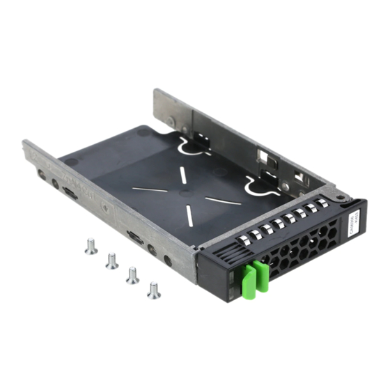
Hot-plug hard disk drives Hot-plug hard disk drives One or two 2.5-inch SAS hard disk drives can be installed in the PRIMERGY BX920 S2 dual-socket server blade. HDD 0 HDD 1 Figure 18: Numbering of the HDD modules The hard disk drives which can be ordered for the server blade BX920 S2 are supplied already mounted in an installation frame so that defective drives can be replaced and new drives can be added during operation. - Page 93 Hot-plug hard disk drives Figure 19: 2.5-inch HDD module and dummy module Dummy module Tabs for unlocking the dummy module HDD module (carrier with hard disk drive installed) Indicators HDD Busy (LED green) HDD Fault (LED orange) For more information see the table on page 42 in section “Control and display...
-
Page 94: Handling Hard Disk Drives And Hdd Modules
Handling hard disk drives and HDD modules Handling hard disk drives and HDD modules Hard disk drives incorporated in the HDD modules are highly sensitive electromagnetic devices and must be handled with great care. Incorrect handling can cause partial or total failure of the hard disk drives. These failures can result in data errors and to a loss of data or to total corruption of the hard disk drive. -
Page 95: Removing/Installing The Dummy Module
Removing/installing the dummy module Removing/installing the dummy module Free slots are provided with dummy modules. Remove the dummy module before installing an additional HDD module. Figure 20: Removing/installing the 2.5-inch dummy module Ê Press both tabs on the dummy module together until the locking mechanism disengages (1). -
Page 96: Installing/Removing The Hdd Module
Installing/removing the HDD module Installing/removing the HDD module Installing the HDD module Figure 21: Unlocking the 2.5-inch HDD module Ê Press the two green tabs of the locking lever together (1). Ê Push the handle of the HDD module fully in the direction of the arrow (2). The HDD module is now unlocked. - Page 97 Installing/removing the HDD module Figure 22: Installing the HDD module Ê Carefully push the HDD module into the empty slot until it stops. Ê Push the handle as far as it will go in the direction of the arrow until the locking mechanism is engaged.
- Page 98 Installing/removing the HDD module If you want to remove a HDD module during operation, proceed as follows: Ê If you want to remove a HDD module that is not defective, the drive must be first set to "Offline" via the software (RAID controller configuration software). Ê...
-
Page 99: Index
Index connect acclimatization time 31, external devices Advanced Video Redirection connecting ambient conditions cables ASR&R consumables availability correcting faults CSS indicator 41, BIOS data changes security functions data protection BIOS Setup data security access date, incorrect Advanced menu, memory delivery note configuration Disconnecting Advanced menu, Peripheral... - Page 100 Index error HDD module drifting display on monitor acclimatization time 31, drive “dead” dummy module drive defective handling incorrect date installation frame incorrect time installing/removing no display on monitor screen remains blank ID button screen shows flickering ID card stripes product name server switches itself off serial number...
- Page 101 Index Screen meaning of the symbols flickering MegaRAID screen mezzanine card error message monitor remains blank display drifts shows flickering stripes no display security functions setup password system password notational conventions unauthorized access serial number Server On/Off button transportation overload server overview ambient conditions...
- Page 102 Index slot, expansion card switch-off time defining switch-on time defining switching off system switching on system system switching off switching on system board, features system does not boot system password target group technical data time, incorrect tips TPM 10, transport damage troubleshooting troubleshooting, server Trusted Platform Module...