Table of Contents
Advertisement
Model Number:
5900798
5900799
5900943
5900500
5901295
This manual is available in Spanish. For a copy, contact your Ferris dealer or www.ferrisindustries.com.
Este manual está disponible en Español. Para obtener una copia, póngase en contacto con su
OPERATOR'S
MAnuAl
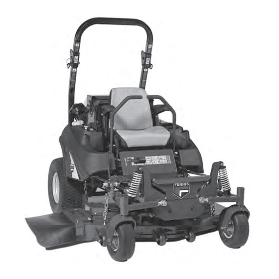
IS2500Z Series
Zero-Turn Riding Mower
Description
IS2500ZY20D52, 52" Cut Zero-Turn Riding Mower
IS2500ZY24D61, 61" Cut Zero-Turn Riding Mower
IS2500ZY20D52HT, 52" Cut Zero-Turn Riding Mower
IS2500ZY24D52, 52" Cut Zero-Turn Riding Mower
IS2500ZY24D61, 61" Cut Zero-Turn Riding Mower
distribuidor Ferris o www.ferrisindustries.com.
5102575
Rev K
Advertisement
Table of Contents
Troubleshooting

Related Manuals for Ferris 5900799


Summary of Contents for Ferris 5900799
- Page 1 5901295 IS2500ZY24D61, 61” Cut Zero-Turn Riding Mower This manual is available in Spanish. For a copy, contact your Ferris dealer or www.ferrisindustries.com. Este manual está disponible en Español. Para obtener una copia, póngase en contacto con su distribuidor Ferris o www.ferrisindustries.com.
- Page 2 Thank you for purchasing this quality-built FERRIS product. We’re pleased that you’ve placed your confidence in the FERRIS brand. When operated and maintained according to the instructions in this manual, your FERRIS product will provide many years of dependable service.
-
Page 3: Table Of Contents
Table of Contents Troubleshooting, Adjustments & Service ..38 Operator Safety ..........2 Troubleshooting the Tractor ........38 Identification Numbers ..........11 Troubleshooting the Mower ........39 Safety Decals ............12 Troubleshooting Common Cutting Problems ..40 Safety Alert Symbol & Signal Words ....13 Seat Adjustment ............41 Safety Icons ............13 Ground Speed Control Lever Adjustment .....41 Safety Interlock System ........14... -
Page 4: Operator Safety
Operator Safety Operating Safety Congratulations on purchasing a superior-quality piece of lawn and garden equipment. Our products are designed and manufactured to meet or exceed all industry standards for safety. Do not operate this machine unless you have been trained. Reading and understanding this operator’s manual is a way to train yourself. -
Page 5: Slope Operation
Operator Safety Slope Operation Operation on slopes can be dangerous. Using the unit on a slope that is too steep where you do not have adequate wheel traction (and control) can cause sliding, loss of steering, control, and possible rollover. You should not operate on a slope greater than a 5.4 foot rise over a 20 foot length (15 degrees). - Page 6 Operator Safety Roll Bar Use Keep the roll bar in the raised position and fasten the seat belt. There is no roll over protection when the roll bar is down! Do not jump off if the mower tips (it is safer to be secured by the seat belt with the roll bar raised.) Lower the roll bar only when necessary (such as to temporarily clear a low overhanging obstacle) and...
- Page 7 Operator Safety Fuel and Maintenance Always disengage all drives, shutoff the engine, and remove the key before doing any cleaning, refueling, or servicing. Gasoline and its vapors are extremely flammable. Do not smoke while operating or refueling. Do not add fuel while engine is hot or running.
- Page 8 Operator Safety Read these safety rules and follow them closely. Failure to obey these rules could result in loss of control of unit, severe personal injury or death to you, or bystanders, or damage to property or equipment. This mowing deck is capable of amputating hands and feet and throwing objects. The triangle in text signifies important cautions or warnings which must be followed.
- Page 9 Operator Safety 23. Use care when approaching blind corners, shrubs, 5. Use extra care with grass catchers or other trees or other objects that may obscure vision. attachments. These can change the stability of 24. To reduce fire hazard, keep unit free of grass, the unit.
- Page 10 Operator Safety EMISSIONS where there is an open flame, such as in a water heater. Allow unit to cool before storing. 1. Engine exhaust from this product contains 5. Shut off fuel while storing or transporting. Do not chemicals known, in certain quantities, to cause store fuel near flames or drain indoors.
- Page 11 Operator Safety leaks. Make sure all hydraulic fluid connections To maintain operator roll over protection and roll bar are tight and all hydraulic hoses and lines are in effectiveness: good condition before applying pressure to the • If a ROLL BAR becomes damaged for any reason, system.
- Page 12 Operator Safety WARNING INSPECT BUCKLE & LATCH Failure to properly inspect and maintain the seat belt can cause serious injury or death. INSPECTION AND MAINTENANCE OF THE ROLL BAR SEAT BELT • The seat belt like the ROLL BAR, needs to be periodically inspected to verify that the integrity has not been compromised through normal machine use, misuse, age degradation,...
-
Page 13: Identification Numbers
Operator Safety Identification Numbers Tractor Identification When contacting your authorized dealer for replacement parts, service, or information you Figure 1. Identification Tag Locations MUST have these numbers. A. Tractor Identification Tag Record your model/serial number and engine serial numbers on the space provided for easy access. These numbers can be found in the locations shown in Figure 1. -
Page 14: Safety Decals
Operator Safety Safety Decals Before operating your unit, read the safety decals. The cautions and warnings are for your safety. To avoid a personal injury or damage to the unit, understand and follow all safety decals. WARNING If any safety decals become worn or damaged, and cannot be read, order replacement decals from your local dealer. -
Page 15: Safety Alert Symbol & Signal Words
Operator Safety Safety Alert Symbol and Signal Words Safety Icons The alert symbol is used to identity safety information about hazards that can result in personal injury. A signal word (DANGER, WARNING, or CAUTION) is used with the alert symbol to indicate the likelihood and the potential severity of the injury. -
Page 16: Safety Interlock System
Operator Safety Safety Interlock System This unit is equipped with safety interlock switches. These safety systems are present for your safety, do not attempt to bypass safety switches, and never tamper with safety devices. Check their operation regularly. Operational SAFETY Checks Test 1 —... -
Page 17: Features & Controls
Features and Controls Features and Controls A. S/N: 2014582798 & Below B. S/N: 2014582799 & Above Control Functions The information below briefly describes the function of individual controls. Starting, stopping, driving, and mowing require the combined use of several controls applied in specific sequences. To learn what combination and sequence of controls to use for various tasks see the OPERATION section. -
Page 18: Oil Pressure Indicator
Features and Controls Deck Lift Pedal, Cutting Ignition Switch Height Adjustment Pin & Deck (S/N: 2015276815 & Above): Lift Lock Lever The ignition switch starts and stops the engine, it has These control the cutting height of the mower deck. three positions: Depress the pedal until it locks into the 5”... -
Page 19: Operation
Operation Operation WARNING General Operating Safety Do not use this machine on slopes greater than 15 degrees. Before first time operation: Select slow ground speed before driving onto • Be sure to read all information in the Safety and a slope. Use extra caution when operating on Operation sections before attempting to operate slopes with a rear-mounted grass catcher. -
Page 20: Priming The Fuel System
Operation Priming the Fuel System Priming the fuel system removes any air bubbles from the fuel system. WARNING Fuel leaked or spilled onto hot surfaces or electrical components can cause a fire. To help prevent possible injury, turn the ignition switch off when changing fuel filter or water separator element. -
Page 21: Starting The Engine
Operation Pushing the Rider by Hand WARNING If you do not understand how a specific control DO NOT TOW RIDER functions, or have not yet thoroughly read the Towing the unit will cause hydraulic pump FEATURES & CONTROLS section, do so now. and wheel motor damage. -
Page 22: Zero Turn Driving Practice
Operation Zero-Turn Driving Practice Smooth Travel The lever controls of The lever controls of the Zero Turn rider are the Zero Turn rider are responsive. Learning how to gain smooth, efficient responsive. control of the rider’s forward, reverse, and turning movements will take some practice. -
Page 23: Advanced Driving
Operation Practice Turning Around a Corner Practice Turning In Place While traveling forward allow one handle to gradually To turn in place, “Zero Turn,” gradually move one return back toward neutral. Repeat several times. ground speed control lever forward from neutral and the other lever back from neutral simultaneously. -
Page 24: Mowing
Operation Mowing 1. Engage the parking brake. Make sure the PTO switch is disengaged, the motion control levers are locked in the NEUTRAL position, and the operator is on the seat. 2. Start the engine (see STARTING THE ENGINE). 3. Set the mower cutting height. 4. -
Page 25: Mowing Methods
Operation When and How Often to Mow The time of day and condition of the grass greatly affect the results you’ll get when mowing. For the best results, follow these guidelines: 1. Mow when the grass is between three and five inches high. -
Page 26: Attaching A Trailer
Operation Proper Mulching Attaching a Trailer Mulching consists of a mower deck which cuts and The maximum weight of a towed trailer should be recuts clippings into tiny particles and then blows less than 200 lbs (91kg). Secure the trailer with a them down INTO the lawn. -
Page 27: Raise & Lower The Roll Bar
Operation Raise & Lower the Roll Bar To lower the roll bar: 1. Pull the hair pin clips (A, Figure 11) out of the retainer pins (B). 2. Push or pull the top of the roll bar (C) forward against the rubber stops (D) and remove the retainer pins (B). -
Page 28: Storage
Operation Storage WARNING Temporary Storage (30 Days Or Less) Never store the unit, with diesel fuel in engine Remember, the fuel tank will still contain some fuel, so or fuel tank, in a heated shelter or in enclosed, never store the unit indoors or in any other area where poorly ventilated enclosures. -
Page 29: Regular Maintenance
Regular Maintenance Maintenance Maintenance Schedule & Procedures The following schedule should be followed for normal care of your rider and mower. You will need to keep a record of your operating time. Determining operating time is easily accomplished by observing the hour meter. RIDER MAINTENANCE ENGINE MAINTENANCE Before Each Use... -
Page 30: Checking/Adding Fuel
Regular Maintenance Checking / Adding Fuel Fuel Filter This unit is equipped with two fuel filters. One is To add fuel: a water separator (A, Figure 14) and the other is a 1. Remove the fuel cap (A, Figure 13). fuel filter (C). -
Page 31: Service Air Filter
Regular Maintenance 6. Loosen the hose clamps that secure the hoses to the fuel filter. 7. Remove the hoses from the filter. 8. Install the new filter in the proper flow direction in the fuel line. 9. Secure with the hose clamps and wipe up any spilled fuel. -
Page 32: Check Hydraulic Oil Level
NOTE: Removing the oil filter from the filter base will drain the oil reservoir. Have a suitable container ready to catch any spilled oil. Ferris recommends this be a dealer-only service item. 1. Locate the transmission oil filter (A, Figure 17). -
Page 33: Check Engine Coolant Level
Regular Maintenance Check Engine Coolant Level WARNING If engine is warm, DO NOT remove radiator cap. Escaping steam can cause burns. Never remove the radiator cap or radiator reservoir cap while the engine is hot or FULL running. Severe thermal burns or injury can occur by escaping steam or hot coolant. -
Page 34: Lubrication
Use grease fittings when present. Disassemble parts to apply grease to moving parts when grease fittings are not installed. Not all greases are compatible. Ferris Red Grease (p/n 5022285) is recommended, automotive-type high-temperature, lithium grease may be used when this is not available. - Page 35 Regular Maintenance Lubricating the Drive Shaft Maintenance Interval: Every 250 hours. 1. Position the drive shaft so that the plug (A, Figure 26) can be accessed from beneath the machine through the hole in the engine cradle. 2. Remove the plug and install a 1/4-28 grease fitting.
-
Page 36: Cleaning The Battery & Cables
Regular Maintenance Cleaning the Battery and Cables NOTE: This unit is equipped with a maintenance-free BCIU1 battery. Removing the Floor Pan to Access the Battery: S/N: 2014696070 & Below: 1. Tilt the left side of the floor pan (C, Figure 28) up so that the locking pins clear the holes in the frame. -
Page 37: Servicing The Mower Blades
Regular Maintenance Servicing the Mower Blades Removing the Mower Blade CAUTION Avoid injury. Mower blades are sharp. • Always wear gloves when handling mower blades or working near blades. 1. To remove the mower blade, wedge a wooden block between the mower blade and the mower deck housing to keep the blade from turning and remove the mower blade mounting bolt with a 15/16”... - Page 38 Regular Maintenance Sharpening the Mower Blades CAUTION Avoid injury. Mower blades are sharp. • Always wear gloves when handling mower blades or working near blades. • Always wear safety eye protection when grinding 1. Sharpen the mower blade with a grinder, hand file, Figure 32.
-
Page 39: Fuse Location
Regular Maintenance Fuse Location The fuse block is located on the side of the instrument control panel mounted on the right hand side fuel tank. Refer to Figure 35 for the location and amperage of the fuses used in this machine. S/N 2015276814 &... -
Page 40: Troubleshooting, Adjustments & Service
Troubleshooting, Adjustment & Repair Troubleshooting WARNING While normal care and regular maintenance will To avoid serious injury, perform maintenance extend the life of your equipment, prolonged or on the tractor or mower only when the engine constant use may eventually require that service be is stopped and the parking brake engaged. -
Page 41: Troubleshooting The Mower
Troubleshooting, Adjustment & Repair Rider Troubleshooting Continued. PROBLEM CAUSE REMEDY Engine runs, but rider will 1. Hydraulic release valve(s) 1. Turn valve(s) clockwise to close. not drive. in “open” position. 2. Belt is broken. 2. See Drive Belt Replacement. 3. Drive belt slips. 3. -
Page 42: Troubleshooting Common Cutting Problems
Troubleshooting, Adjustment & Repair Troubleshooting Common Cutting Problems PROBLEM CAUSE REMEDY Streaking. 1. Blades are not sharp. 1. Sharpen your blades. 2. Blades are worn down to far. 2. Replace your blades. 3. Engine speed is too slow. 3. Always mow at full throttle. 4. -
Page 43: Seat Adjustment
Troubleshooting, Adjustment & Repair Seat Adjustment S/N: 2014582798 & S/N: 2014582799 & The seat can be adjusted forward and back. Below Above S/N: 2014582798 & Below: Move the seat adjustment lever (A, Figure 37) forward, position the seat as desired, and release the lever to lock the seat into position. -
Page 44: Neutral Adjustment
Troubleshooting, Adjustment & Repair Neutral Adjustment If the tractor “creeps” while the ground speed control levers are locked in NEUTRAL, then it may be necessary to adjust the linkage rod. NOTE: Perform this adjustment on a hard, level surface such as a concrete floor. 1. -
Page 45: Parking Brake Adjustment
D. Parking Brake Bracket 6. Engage the parking brake and re-measure the spring. 7. Position the set collar (C) 1/4” (0,25 cm) away from the parking brake bracket (D) and tighten. If this does not correct the braking problem, see your Ferris dealer. -
Page 46: Suspension Adjustment
Troubleshooting, Adjustment & Repair Suspension Adjustment To adjust the spring pre-load: 1. Park machine on a flat, level surface. Disengage The shock assembly can be adjusted to vary the the PTO, stop the engine and engage the parking amount of pre-load applied to the springs. This allows brake. -
Page 47: Mowing Height Adjustment
Troubleshooting, Adjustment & Repair Mowing Height Adjustment The cutting height adjustment pin (A, Figure 44) controls the mower cutting height. The cutting height is adjustable between 1-3/4” (4,4 cm) and 5” (12,7 cm) in 1/4” (0,64 cm) increments. 1. Depress the deck lift foot pedal (B) until it locks into the 5”... -
Page 48: Deck Lift Rod Timing Adjustment
Troubleshooting, Adjustment & Repair Deck Lift Rod Timing Adjustment Inner Rod 1. Park machine on a flat, level surface. Disengage the PTO, stop the engine and engage the parking brake. Rear tires must be inflated to 18 psi (1,24 bar); front tires to 25 psi (1,72 bar). 2. -
Page 49: Deck Leveling Adjustment
Troubleshooting, Adjustment & Repair Deck Leveling Adjustment NOTE: Before adjusting the deck level, the deck lift rod timing must be checked and/or adjusted. Coarse Adjustment Procedure When adjusting the deck level, the coarse adjustment procedure should be used to make the majority of the adjustment and the Fine Adjustment Procedure should be used to complete the adjustment. -
Page 50: Deck Lift Spring
Troubleshooting, Adjustment & Repair Fine Adjustment Procedure (52” Models; 61” Models - S/N: 2016564122 & Above) 1. Loosen the jam nut (A, Figure 52) and turn the fine adjustment bolt (B) to adjust the deck height until the front measurement equals 4” (10,2 cm) and the back measurement equals 4”... -
Page 51: Hydraulic Pump Drive Belt Replacement
Troubleshooting, Adjustment & Repair Hydraulic Pump Drive Belt Replacement To avoid damaging belts, DO NOT PRY BELTS OVER PULLEYS. 1. Park the tractor on a smooth, level surface such as a concrete floor. Disengage the PTO, engage the parking brake, turn off the engine, and remove the ignition key. - Page 52 Troubleshooting, Adjustment & Repair 9. Install the drive belt on the idler arm pulley and check to make sure that the V-side of the belt runs in the pulley grooves. See Figure 55. 10. Carefully rotate the breaker bar CLOCKWISE and install the belt on the right pump drive pulley (B, Figure 55).
-
Page 53: Pto Clutch Belt Replacement
Troubleshooting, Adjustment & Repair PTO Clutch Belt Replacement 1. Park the tractor on a smooth, level surface such as a concrete floor. Disengage the PTO, engage the parking brake, turn off the engine, and remove the ignition key. 2. Open the hood to gain access to the PTO clutch belts (A, Figure 58) which is located on the rear of the engine. -
Page 54: Mower Belt Replacement
Troubleshooting, Adjustment & Repair Mower Belt Replacement 52” Deck To avoid damaging belts, DO NOT PRY BELTS OVER PULLEYS. 1. Park the tractor on a smooth, level surface such as a concrete floor. Disengage the PTO, engage the parking brake, turn off the engine, and remove the ignition key. -
Page 55: Deck Shut Down Module
Troubleshooting, Adjustment & Repair Check the Mower Belt Tensioner Spring Length 1. Park the machine on a smooth level surface such as a concrete floor. Disengage the PTO, engage the parking brake, turn off the engine and remove the ignition key. 2. -
Page 56: Battery Service
Troubleshooting, Adjustment & Repair Battery Service freely at low charging rate and less than 0.003 change in specific gravity occurs over a three hour WARNING period. Jump Starting With Auxiliary (Booster) Battery Keep open flames and sparks away from the battery;... - Page 57 Troubleshooting, Adjustment & Repair THIS HOOK-UP FOR NEGATIVE GROUND VEHICLES Starter Starter Switch Switch Jumper Cable Starting Discharged Vehicle Vehicle Battery Battery Jumper Cable To Ground Engine Block MAKE CERTAIN VEHICLES DO NOT TOUCH Figure 63. Jump Starting WARNING WARNING Any procedure other than the preceding could For your personal safety, use extreme care result in:...
-
Page 58: Specifications
Specifications Specifications TRANSMISSIONS: (S/N: 2014390038 & Below): NOTE: Specifications are correct at time of printing Hydro-Gear HGM-18E-3056 (5022975L) and are subject to change without notice. Hydro-Gear PK 3HBQ-FV1F-XXXX (5102174) Hydro-Gear HGM-18E-3052 (5022975R) ENGINE: Hydro-Gear PK 3KBQ-FV1F-XXXX (5102175) (S/N: 2014390039 & Above): 20 Gross HP¹... - Page 59 Notes...
- Page 60 Notes...
-
Page 62: Limited Warranty
ABOUT YOUR WARRANTY We welcome warranty repair and apologize to you for being inconvenienced. Warranty service is available only through FERRIS Authorized Service Dealers. Most warranty repairs are handled routinely, but sometimes requests for warranty service may not be appropriate. This warranty only covers defects in materials or workmanship. It does not cover damage caused by improper use or abuse, improper maintenance or repair, normal wear and tear, or stale or unapproved fuel. -
Page 63: Your Warranty Rights And Obligations
California, U.S. EPA, and Briggs & Stratton Corporation Emissions Control Warranty Statement September 2012 Your Warranty Rights And Obligations The California Air Resources Board, U.S. EPA, and Briggs & Stratton (B&S) are pleased Owner’s Warranty Responsibilities: to explain the emissions control system warranty on your Model Year 2012--2013 ... - Page 64 OPERATOR’S MAnuAl IS2500Z Series Zero-Turn Riding Mower...