Honda EB4000X Owner's Manual
Generator
Hide thumbs
Also See for EB4000X:
- Owner's manual (90 pages) ,
- Information (28 pages) ,
- Owner's manual (96 pages)

Related Manuals for Honda EB4000X


Summary of Contents for Honda EB4000X
- Page 1 Owner’s Manual GENERATOR EB4000X • EB5000X • EB6500X Click to Save As See page 80 for Initial Use Instructions © 2014 Honda Motor Co., Ltd.—All Rights Reserved...
- Page 2 The information and specifications included in this publication were in effect at the time of approval for printing. Honda Motor Co., Ltd. reserves the right, however, to discontinue or change specifications or design at any time without notice and without incurring any obligation whatsoever.
- Page 3 INTRODUCTION Congratulations on your selection of a Honda generator. We are certain you will be pleased with your purchase of one of the finest generators on the market. We want to help you get the best results from your new generator and to operate it safely.
- Page 4 A FEW WORDS ABOUT SAFETY Your safety and the safety of others are very important. And using this generator safely is an important responsibility. To help you make informed decisions about safety, we have provided operating procedures and other information on labels and in this manual.
-
Page 5: Table Of Contents
CONTENTS GENERATOR SAFETY ..............6 IMPORTANT SAFETY INFORMATION ......... 6 Operator Responsibility ............6 Carbon Monoxide Hazards ............6 Electric Shock Hazards............7 Fire and Burn Hazards ............7 Refuel With Care ..............8 SAFETY LABEL LOCATIONS............9 CONTROLS & FEATURES ............10 COMPONENT &... - Page 6 CONTENTS OPERATION................24 SAFE OPERATING PRECAUTIONS ..........24 STARTING THE ENGINE ............25 STOPPING THE ENGINE ............28 GFCI OPERATION CHECK............29 AC OPERATION ..............31 AC Applications ..............33 AC Receptacle Selection ............34 Power Producing Circuits ............. 34 Voltage Selector Switch............
- Page 7 Air Index ................68 Specifications ..............69 Wiring Diagram ..............70 CONSUMER INFORMATION............72 Dealer Locator Information ........... 72 Honda Publications .............. 72 Customer Service Information ..........73 ASSEMBLY................74 SAFETY ................74 The Importance of Proper Assembly ........74 Important Safety Precautions..........
-
Page 8: Generator Safety
GENERATOR SAFETY IMPORTANT SAFETY INFORMATION Honda generators are designed for use with electrical equipment that has suitable power requirements. Other uses can result in injury to the operator or damage to the generator and other property. Most injuries or property damage can be prevented if you follow all instructions in this manual and on the generator. -
Page 9: Electric Shock Hazards
GENERATOR SAFETY Electric Shock Hazards • The generator produces enough electric power to cause a serious shock or electrocution if misused. • Using a generator or electrical appliance in wet conditions, such as rain or snow, or near a pool or sprinkler system, or when your hands are wet, could result in electrocution. -
Page 10: Refuel With Care
GENERATOR SAFETY Refuel With Care Gasoline is extremely flammable, and gasoline vapor can explode. Allow the engine to cool if the generator has been in operation. Refuel only outdoors in a well ventilated area with the engine off. Do not refuel during operation. Do not overfill the fuel tank. -
Page 11: Safety Label Locations
GENERATOR SAFETY SAFETY LABEL LOCATIONS These labels warn you of potential hazards that can cause serious injury. Read them carefully. If a label comes off or becomes hard to read, contact your Honda generator dealer for a replacement. -
Page 12: Controls & Features
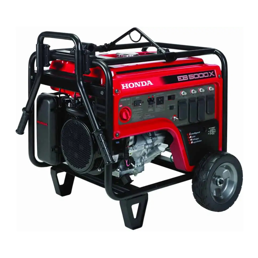
Use the illustrations on these pages to locate and identify the most frequently used controls. AC CIRCUIT PROTECTORS VOLTAGE SELECTOR SWITCH GFCI TEST BUTTON 120 V/240 V AC RECEPTACLE GFCI RESET BUTTON ENGINE SWITCH 120 V AC RECEPTACLES GROUND TERMINAL AUTO THROTTLE SWITCH AC CIRCUIT BREAKER *: Except EB4000X... - Page 13 CONTROLS & FEATURES FUEL TANK CAP CONTROL PANEL AIR CLEANER FUEL VALVE LEVER SEDIMENT CUP STARTER GRIP OIL FILLER CAP/DIPSTICK OIL DRAIN PLUG LIFTING HANGER HANDLE FUEL GAUGE SPARK PLUG STAND WHEEL MUFFLER MANUAL CHOKE LEVER...
-
Page 14: Controls
CONTROLS & FEATURES CONTROLS Engine Switch The engine switch controls the ignition system. OFF – Stops the engine. ON – Running position, and for starting. ENGINE SWITCH Starter Grip Pulling the starter grip operates the recoil starter to crank the engine. -
Page 15: Fuel Valve Lever
CONTROLS & FEATURES Fuel Valve Lever The fuel valve lever is located between the fuel tank and carburetor. The fuel valve must be in the ON position for the engine to run. After stopping the engine, turn the fuel valve to the OFF position. FUEL VALVE LEVER Voltage Selector Switch The voltage selector switch switches generator output to produce... -
Page 16: Auto Throttle System
CONTROLS & FEATURES Auto Throttle® System The Auto Throttle® system automatically reduces engine speed when all loads are turned off or disconnected. When appliances are turned on or reconnected, the engine returns to the rated speed. Switch Position Recommended to minimize fuel consumption and further reduce noise levels when no load is applied to the generator. -
Page 17: Ac Circuit Protectors
AC circuit protector ON. AC CIRCUIT PROTECTOR for Receptacle (4) AC CIRCUIT PROTECTOR for Receptacle (3) (4) 120 V/240 V 20 A (EB4000X) 120 V/240 V 30 A (EB5000X, AC CIRCUIT PROTECTOR... -
Page 18: Ac Circuit Breaker
CONTROLS & FEATURES AC Circuit Breaker The AC circuit breaker will automatically switch OFF if there is a short circuit or a significant overload at the receptacles, or if the ground fault circuit interrupter (GFCI) detects a ground fault current. The AC circuit breaker may be used to switch the generator power ON or OFF. -
Page 19: Ground Fault Circuit Interrupter (Gfci)
CONTROLS & FEATURES Ground Fault Circuit Interrupter (GFCI) All receptacles on the generator are protected by a Ground Fault Circuit Interrupter (GFCI) for protection against the shock hazard of ground fault current. The GFCI has a TEST and RESET button and is connected to the AC circuit breaker. -
Page 20: Folding Handle
CONTROL & FEATURES Folding Handle The foldable handle is intended for ease of transportation and should be folded when the generator is stationary. Do not rest objects on the extended handle. To Extend The Handle Lift handle upward. Lock lever will lock and secure the handle into place. -
Page 21: Features
If the engine stops, make sure the oil level is correct. Wait a few minutes, and then try to restart the engine. If the engine still won’t start, take the generator to your authorized servicing Honda power equipment dealer. -
Page 22: Auto Choke And Throttle Control System
The total amount of power available for each generator model is: EB4000X: 5,000 watts for up to 10 seconds EB5000X: 7,000 watts for up to 10 seconds EB6500X: 7,000 watts for up to 10 seconds... -
Page 23: Fuel Gauge
CONTROLS & FEATURES Fuel Gauge The fuel gauge is a mechanical device that measures the fuel level in the tank. The red indicator in the window will reference the level in relation to full or empty. To provide increased operating time, start with a full tank before beginning operation. -
Page 24: Before Operation
BEFORE OPERATION ARE YOU READY TO GET STARTED? Your safety is your responsibility. A little time spent in preparation will significantly reduce your risk of injury. Knowledge Read and understand this manual. Know what the controls do and how to operate them. Familiarize yourself with the generator and its operation before you begin using it. -
Page 25: Check The Engine
BEFORE OPERATION To prevent a possible fire, keep the generator at least 3 feet (1 meter) away from building walls and other equipment during operation. Do not place flammable objects close to the engine. Before beginning your pre-operation checks, be sure the generator is on a level surface and the engine switch is in the OFF position. -
Page 26: Operation
OPERATION SAFE OPERATING PRECAUTIONS Before operating the generator for the first time, review chapters GENERATOR SAFETY (see page 6) and BEFORE OPERATION (see page 22). For your safety, do not operate the generator in an enclosed area such as a garage. Your generator’s exhaust contains poisonous carbon monoxide gas that can collect rapidly in an enclosed area and cause illness or death. -
Page 27: Starting The Engine
OPERATION STARTING THE ENGINE To prevent a possible fire, keep the generator at least 3 feet (1 meter) away from building walls and other equipment during operation. Do not place flammable objects close to the engine. Operating this generator less than 3 feet (1 meter) from a building or other obstruction can cause overheating and damage the generator. - Page 28 OPERATION 3.Make sure the Auto Throttle AUTO THROTTLE SWITCH switch is in the OFF position, or more time will be required for warm up. 4.Turn the engine switch to the ON position. ENGINE SWITCH 5.Pull the starter grip lightly until you feel resistance;...
- Page 29 OPERATION 6.If you wish to use the Auto AUTO THROTTLE SWITCH Throttle system, turn the Auto Throttle switch to the ON position after the engine has warmed up for 2 or 3 minutes.
-
Page 30: Stopping The Engine
OPERATION STOPPING THE ENGINE To stop the engine in an emergency, simply turn the engine switch to the OFF position. Under normal conditions, use the following procedure. 1.Turn off or disconnect all appliances that are connected to the generator. 2.Move the AC circuit breaker to the OFF position. -
Page 31: Gfci Operation Check
5.Press the GFCI TEST button. The RESET button should extend, and the AC circuit breaker should switch to the OFF position. If the GFCI and AC circuit breaker do not function as described, take the generator to an authorized Honda generator dealer for repair. GFCI TEST BUTTON GFCI RESET BUTTON... - Page 32 ON position. The AC circuit breaker will not remain in the ON position if the RESET button is extended. If the GFCI and AC circuit breaker do not function as described, take the generator to an authorized Honda generator dealer for repair. AC CIRCUIT BREAKER GFCI RESET BUTTON...
-
Page 33: Ac Operation
OPERATION AC OPERATION If an appliance begins to operate abnormally, becomes sluggish, or stops suddenly, turn it off immediately. Disconnect the appliance, and determine whether the problem is in the appliance or the rated load capacity of the generator has been exceeded. Substantial overloading may damage the generator. - Page 34 AC CIRCUIT PROTECTORS AC CIRCUIT BREAKER PLUG *: Except EB4000X 5.Turn on the appliance. Do not exceed the current limit specified for any one receptacle. If an overloaded circuit causes the AC circuit breaker or AC circuit protector to switch OFF, reduce the electrical load on the circuit, wait a few minutes and then reset the AC circuit breaker or AC circuit protector.
-
Page 35: Ac Applications
Make sure the electrical rating of the tool or appliance does not exceed the maximum power rating of the generator. Maximum power is: EB4000X: 4.0 kVA EB5000X: 5.0 kVA EB6500X: 6.5 kVA For continuous operation, do not exceed the rated power.... -
Page 36: Ac Receptacle Selection
4A and 4B. (1)120 V 30 A (2)120 V 20 A (3)120 V 20 A (4A)&(4B)120 V/240 V 20 A (EB4000X) 120 V/240 V 30 A (EB5000X, EB6500X) *: Except EB4000X Power Producing Circuits This generator is equipped with two power generating circuits. -
Page 37: Voltage Selector Switch
Total Current Available: 30.0 A (EB4000X) 37.5 A (EB5000X) 45.8 A (EB6500X) - Page 38 Divide the load between the two sets of receptacles shown below. Balancing is necessary because each set of receptacles is powered by only one power producing circuit that can produce a maximum of amps(*). 15.0 A (EB4000X) 18.8 A (EB5000X) 22.9 A (EB6500X) Set of...
-
Page 39: Auto Throttle System
OPERATION AUTO THROTTLE® SYSTEM With the switch in the ON position, engine speed is automatically reduced when ALL loads are turned OFF or disconnected. When appliances are turned ON or reconnected, the engine returns to rated speed. In the OFF position, the Auto Throttle system does not operate. The Auto Throttle system will not respond to electrical loads of less than 1 ampere or intermittent loads such as a staple gun. -
Page 40: Standby Power
OPERATION STANDBY POWER Connections to a Building’s Electrical System Connections for standby power to a building’s electrical system must be made by a qualified electrician. The connection must isolate the generator power from utility power, and must comply with all applicable laws and electrical codes. -
Page 41: Special Requirements
OPERATION Special Requirements There may be Federal or State Occupational Safety and Health Administration (OSHA) regulations, local codes, or ordinances that apply to the intended use of the generator. Please consult a qualified electrician, electrical inspector, or the local agency having jurisdiction. •... -
Page 42: Servicing Your Generator
Remember that an authorized Honda servicing dealer knows your generator best and is fully equipped to maintain and repair it. To ensure the best quality and reliability, use only new, Honda Genuine parts or their equivalents for repair and replacement. -
Page 43: Maintenance Safety
SERVICING YOUR GENERATOR MAINTENANCE SAFETY Some of the most important safety precautions follow. However, we cannot warn you of every conceivable hazard that can arise in performing maintenance. Only you can decide whether or not you should perform a given task. Failure to properly follow maintenance instructions and precautions can cause you to be... -
Page 44: Maintenance Schedule
(1) Service more frequently when used in dusty areas. (2) These items should be serviced by your servicing dealer, unless you have the proper tools and are mechanically proficient. Refer to the Honda shop manual for service procedures. See “Honda Publications” on page 72 for ordering information. -
Page 45: Refueling
SERVICING YOUR GENERATOR REFUELING With the engine stopped, check the fuel gauge. Refill the fuel tank if the fuel level is low. Gasoline is highly flammable and explosive. You can be burned or seriously injured when handling fuel. • Stop the engine and keep heat, sparks, and flame away. -
Page 46: Fuel Recommendations
SERVICING YOUR GENERATOR UPPER LEVEL MARK (RED) FUEL LEVEL GAUGE FUEL TANK CAP FUEL FILTER FULL EMPTY UPPER LEVEL MARK (RED) After refueling, reinstall the fuel tank cap securely. FUEL RECOMMENDATIONS This engine is certified to operate on regular unleaded gasoline with a pump octane rating of 86 or higher. -
Page 47: Engine Oil Level Check
SERVICING YOUR GENERATOR ENGINE OIL LEVEL CHECK Check the oil level BEFORE EACH USE with the generator on a level surface and the engine stopped. 1.Remove the oil filler cap/dipstick and wipe it clean. 2.Insert and remove the dipstick without screwing it into the filler neck. Check the oil level shown on the dipstick. -
Page 48: Engine Oil Change
SERVICING YOUR GENERATOR ENGINE OIL CHANGE Drain the oil while the engine is warm to assure rapid and complete draining. 1.Place a suitable container below the engine to catch the used oil, and then remove the oil filler cap/dipstick, 12×15 mm drain plug, and sealing washer. -
Page 49: Engine Oil Recommendations
AMBIENT TEMPERATURE The SAE oil viscosity and service category are in the API label on the oil container. Honda recommends that you use API service category SJ or later (or equivalent) oil. -
Page 50: Air Cleaner Service
SERVICING YOUR GENERATOR AIR CLEANER SERVICE 1.Unsnap the air cleaner cover clips and open the air cleaner cover. 2.Free the hooks from the setting pins on the air cleaner case and remove the air cleaner cover to the right side of the frame pipe, taking care not to damage the air cleaner cover. - Page 51 SERVICING YOUR GENERATOR 5.Reinstall the air cleaner element in the air cleaner case. 6.Set the hooks of the air cleaner cover to the setting pins securely, and then push the air cleaner cover to lock the clips. Be sure that the cover is set securely. There must be no clearance between the air cleaner cover and air cleaner case.
-
Page 52: Air Cleaner Element Cleaning
SERVICING YOUR GENERATOR AIR CLEANER ELEMENT CLEANING A dirty air cleaner element will restrict air flow to the carburetor, reducing engine performance. If you operate the generator in very dusty areas, clean the air cleaner element more frequently than specified in the Maintenance Schedule. -
Page 53: Spark Plug Service
SERVICING YOUR GENERATOR SPARK PLUG SERVICE In order to service the spark plug, you will need a spark plug wrench (commercially available). Recommended spark plugs: BPR5ES (NGK) W16EPR-U (DENSO) To ensure proper engine operation, the spark plug must be properly gapped and free of deposits. - Page 54 SERVICING YOUR GENERATOR 3.Visually inspect the spark plug. Replace it if the electrodes are worn or if the insulator is cracked, chipped, or fouled. 4.Measure the spark plug electrode gap with a wire-type feeler gauge. Correct the gap, if necessary, by carefully bending the side electrode. The gap should be:...
-
Page 55: Spark Arrester Service
SERVICING YOUR GENERATOR SPARK ARRESTER SERVICE The spark arrester must be serviced every 100 hours to keep it functioning as designed. If the engine has been running, the muffler will be very hot. Allow the muffler to cool before servicing the spark arrester. Clean the spark arrester as follows: 1.Remove the two 5 mm screws, and remove the spark arrester. -
Page 56: Sediment Cup Cleaning
SERVICING YOUR GENERATOR SEDIMENT CUP CLEANING The sediment cup prevents dirt or water that may be in the fuel tank from entering the carburetor. If the engine has not been run for a long time, the sediment cup should be cleaned. 1.Turn the engine switch to the OFF position. -
Page 57: Storage
STORAGE STORAGE PREPARATION Proper storage preparation is essential for keeping your generator trouble-free and looking good. The following steps will help to keep rust and corrosion from impairing your generator’s function and appearance, and will make the engine easier to start when you use the generator again. - Page 58 After removal from storage, drain the stored gasoline into a suitable container, and fill with fresh gasoline before starting. * Use gasoline stabilizers that are formulated to extend storage life. Follow the manufacturer’s instructions for use. Contact your authorized Honda generator dealer for stabilizer recommendations.
- Page 59 STORAGE Draining the Fuel Tank and Carburetor Gasoline is highly flammable and explosive. You can be burned or seriously injured when handling fuel. • Stop the engine and keep heat, sparks, and flame away. • Handle fuel only outdoors. • Wipe up spills immediately. 1.Turn the fuel valve lever to the OFF position.
-
Page 60: Engine Oil
STORAGE 4.After all the gasoline has drained into the container, tighten the carburetor drain screw securely. 5.Place a suitable gasoline container below the sediment cup, and use a funnel to avoid spilling gasoline. 6.Remove the sediment cup (see page 54), and then turn the fuel valve lever to the ON position and drain the fuel from the fuel tank. -
Page 61: Storage Precautions
STORAGE STORAGE PRECAUTIONS If your generator will be stored with gasoline in the fuel tank and carburetor, it is important to reduce the hazard of gasoline vapor ignition. Select a well ventilated storage area away from any appliance that operates with a flame, such as a furnace, water heater, or clothes dryer. Also avoid any area with a spark-producing electric motor, or where power tools are operated. -
Page 62: Transporting
TRANSPORTING Do not lay the generator on its side when moving, storing, or operating it. Oil or fuel may leak and damage the engine or your property. If the generator has been running, allow the engine to cool for at least 15 minutes before loading the generator on the transport vehicle. -
Page 63: Taking Care Of Unexpected Problems
(see page 52). Spark plug wet with fuel Dry and reinstall spark plug. (flooded engine). Take the generator to an Fuel filter restricted, carburetor malfunction, ignition malfunction, authorized Honda servicing dealer, valves stuck, etc. or refer to the shop manual. -
Page 64: Engine Lacks Power
(see page 57). refueled with bad gasoline. Refuel with fresh gasoline (see page 43). Take the generator to an Fuel filter restricted, carburetor malfunction, ignition malfunction, authorized Honda servicing dealer, valves stuck, etc. or refer to the shop manual. -
Page 65: No Power At The Ac Receptacles
Internal circuit overheated. Stop the engine. Reduce the electrical load. Wait a few minutes for the internal circuit to cool down. Restart the engine. Take the generator to an Faulty generator. authorized Honda servicing dealer, or refer to the shop manual. -
Page 66: Technical Information
TECHNICAL INFORMATION Serial Number Location ENGINE SERIAL NUMBER FRAME SERIAL NUMBER Record the frame serial number and date purchased in the spaces below. You will need this information when ordering parts and when making technical or warranty inquiries. Engine serial number: Frame serial number: Date purchased:... -
Page 67: Carburetor Modification For High Altitude Operation
High altitude performance can be improved by specific modifications to the carburetor. If you always operate your generator at altitudes above 5,000 feet (1,500 meters), have your authorized Honda servicing dealer perform this carburetor modification. This engine, when operated at high altitude with the carburetor modifications for high altitude use, will meet each emission standard throughout its useful life. -
Page 68: Emission Control System Information
Carbon monoxide does not react in the same way, but it is toxic. Honda utilizes appropriate air/fuel ratios and other emissions control systems to reduce the emissions of carbon monoxide, oxides of nitrogen, and hydrocarbons.... - Page 69 • Afterburning (backfiring). • Black exhaust smoke or high fuel consumption. Replacement Parts The emission control systems on your new Honda engine were designed, built, and certified to conform with applicable emission regulations. We recommend the use of Honda Genuine parts whenever you have maintenance done.
-
Page 70: Air Index
TECHNICAL INFORMATION Air Index An Air Index Information label is applied to engines certified to an emission durability time period in accordance with the requirements of the California Air Resources Board. The bar graph is intended to provide you, our customer, the ability to compare the emissions performance of available engines. -
Page 71: Specifications
TECHNICAL INFORMATION Specifications Dimensions Model EB4000X EB5000X EB6500X Type AT type Description code EBSC EBPC EBLC Length 41.1 in 41.4 in (1,043 mm) (1,051 mm) Width 27.8 in (706 mm) Height 30.4 in (773 mm) Dry mass [weight] 188.3 lbs 212.3 lbs... -
Page 72: Wiring Diagram
TECHNICAL INFORMATION Wiring Diagram Abbreviations Wire color code Symbol Part name BLACK YELLOW AC O AC Outlet BLUE AC CB AC Circuit Breaker GREEN AuSw Auto Throttle Switch Control Box Block WHITE Current Transformer BROWN D-AVR Digital-Automatic LIGHT GREEN Voltage Regulator GRAY D-CDI Digital-CDI... - Page 73 TECHNICAL INFORMATION EB4000X: *1 ∙ EB5000X, EB6500X: *2...
-
Page 74: Consumer Information
CONSUMER INFORMATION Dealer Locator Information To find an authorized Honda Servicing Dealer anywhere in the United States: Visit our website: http://powerequipment.honda.com/dealer-locator Honda Publications Shop Manual This manual covers complete maintenance and overhaul procedures. It is intended to be used by a skilled technician. -
Page 75: Customer Service Information
CONSUMER INFORMATION Customer Service Information Honda Power Equipment dealership personnel are trained professionals. They should be able to answer any question you may have. If you encounter a problem that your dealer does not solve to your satisfaction, please discuss it with the dealership’s management.... -
Page 76: Assembly
ASSEMBLY SAFETY The Importance of Proper Assembly Proper assembly is essential to operator safety and the reliability of the machine. Any error or oversight made by the person assembling and servicing a unit can easily result in faulty operation, damage to the machine, or injury to the operator. -
Page 77: Important Safety Precautions
ASSEMBLY Important Safety Precautions • Make sure you have a clear understanding of all basic shop safety practices and that you are wearing appropriate clothing and safety equipment. When performing this assembly, be especially careful of the following: □ Read the instructions before you begin, and be sure you have the tools and skills required to perform the tasks safely. -
Page 78: Assembly
ASSEMBLY ASSEMBLY Unpacking 1.Remove the generator and loose parts box from the carton. 2.Compare the loose parts with the inventory list below. Tools Required: 12 mm wrench (2), pliers Loose Parts (Wheel kit, handle and hanger) Check all loose parts against the following list. Contact your dealer if any of the loose parts shown below are not included with your generator. -
Page 79: Wheel Kit Installation
ASSEMBLY Wheel Kit Installation 1.Install the two wheels on the axle shaft using the washers and split pins. 2.Install the axle assembly on the generator using four 8×16 mm flange bolts and 8 mm flange nuts. 3.Install the two stands on the under frame using four 8×16 mm flange bolts. -
Page 80: Handle Installation
ASSEMBLY Handle Installation 1.Install the handle folder assembly on the generator upper frame using the 8×18 mm flange bolts. 2.Install the handle assembly on the generator upper frame pipe using the 8×16 mm flange bolts, handle bush A, handle bush B, and handle lower bracket. -
Page 81: Hanger Kit Installation
ASSEMBLY Hanger Kit Installation 1.Position the hanger at the generator’s balance point as shown below. 2.Fit the end tabs of the hanger through the bracket slots, and bolt the brackets to the hanger and tighten securely. TORQUE: 17–22 lbf·ft (24–29 N·m, 2.4–3.0 kgf·m) HANGER 8×16 mm FLANGE BOLT (4) HANGER BRACKET (2) -
Page 82: Initial Use Instructions
INITIAL USE INSTRUCTIONS ENGINE OIL The generator is shipped WITHOUT OIL in the engine. 1.Place the generator on a level surface. 2.Remove the oil filler cap/dipstick. 3.Add enough oil to bring the oil level to the upper limit mark on the oil dipstick. -
Page 83: Fuel
INITIAL USE INSTRUCTIONS FUEL Add fuel to the generator in a well-ventilated area. Never refuel the engine inside a building where gasoline fumes may reach flames or sparks. Keep gasoline away from appliance pilot lights, barbecues, electric appliances, power tools, etc. Spilled fuel is not only a fire hazard, it causes environmental damage. -
Page 84: Before Operation
Please Register Your Generator If your dealer did not collect registration information from you, please take a few minutes and register your purchase with Honda. This allows us to contact you with any important updates regarding your generator. Please note registration is not required to obtain warranty service. You can register your generator by visiting the Honda Power Equipment website, www.hondapowerequipment.com and selecting Product... -
Page 85: Index
INDEX Abnormal Voltage Detection Function ........19 AC Applications ..............33 AC Circuit Breaker..............16 AC Circuit Protectors .............. 15 AC OPERATION ..............31 AC Receptacle Selection ............34 AIR CLEANER ELEMENT CLEANING.......... 50 AIR CLEANER SERVICE............48 Air Index ................68 ARE YOU READY TO GET STARTED?........ - Page 86 Ground Fault Circuit Interrupter (GFCI) ........17 Ground Terminal ..............21 Handle Installation ..............78 Hanger Kit Installation............. 79 Honda Publications ..............72 iAVR (Intelligent Auto Voltage Regulator) ........20 IMPORTANT SAFETY INFORMATION ......... 6 Important Safety Precautions ........... 75 INITIAL USE INSTRUCTIONS ...........
- Page 87 INDEX Knowledge ................22 Loose Parts ................76 MAINTENANCE SAFETY ............41 MAINTENANCE SCHEDULE ............. 42 NO POWER AT THE AC RECEPTACLES ........63 Oil Alert Function ..............19 Oil Alert System..............19 OPERATION................24 Operator Responsibility ............. 6 Overspeed Detection Function ..........19 Power Producing Circuits ............
- Page 88 INDEX SAFE OPERATING PRECAUTIONS ..........24 SAFETY ................74 SAFETY LABEL LOCATIONS............9 Safety Precautions ..............41 SEDIMENT CUP CLEANING ............. 54 Serial Number Location ............64 SERVICING YOUR GENERATOR ..........40 SPARK ARRESTER SERVICE ............ 53 SPARK PLUG SERVICE............51 Special Requirements..............
- Page 89 MEMO...
- Page 90 MEMO...
-
Page 91: Quick Reference Information
QUICK REFERENCE INFORMATION Fuel Type Unleaded gasoline with an ethanol content of no more than 10% and a pump octane rating of 86 or higher Engine Oil Type SAE 10W-30, API SJ or later (or equivalent), for general use (see page 47) Spark Plug Type BPR5ES (NGK)... - Page 92 AHM.35.2014.02 31Z23801 Printed on PRINTED IN U.S.A. 00X31-Z23-8010 Recycled Paper...