Table of Contents
Advertisement
Quick Links
Advertisement
Table of Contents

Related Manuals for HP 100B SFF


Summary of Contents for HP 100B SFF
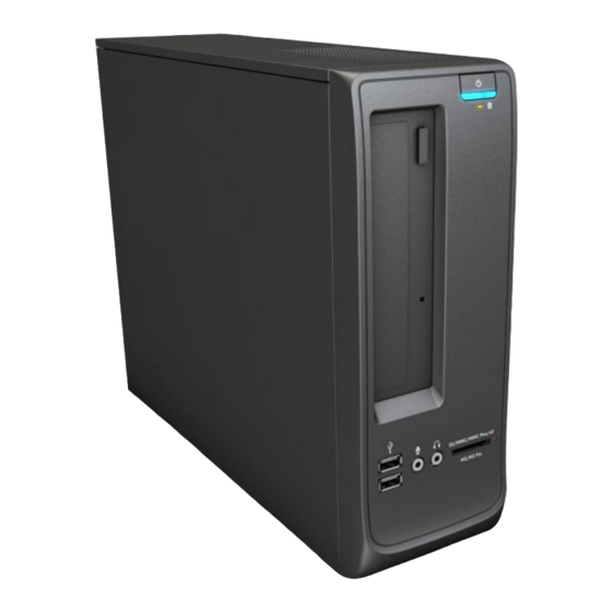
- Page 1 Maintenance & Service Guide 100B SFF PC...
- Page 2 Nothing herein should be construed as constituting an additional warranty. HP shall not be liable for technical or editorial errors or omissions contained herein. This document contains proprietary information that is protected by copyright.
-
Page 3: About This Book
About This Book WARNING! Text set off in this manner indicates that failure to follow directions could result in bodily harm or loss of life. CAUTION: Text set off in this manner indicates that failure to follow directions could result in damage to equipment or loss of information. -
Page 5: Table Of Contents
Table of contents Installing and Customizing the Software ................1 Installing the Operating System ......................1 Downloading Microsoft Windows Updates ....................2 Installing or Upgrading Device Drivers (Windows systems) ................. 2 Accessing Disk Image (ISO) Files ......................2 Protecting the Software ......................... 2 2 Computer Setup (F10) Utility .................... - Page 6 Populating DIMM Sockets ......................25 Installing DIMMs ........................26 Cable Management ........................... 28 Cable Connections ........................28 100B SFF PC ....................... 28 Drives ............................... 29 Drive Positions ........................... 29 Installing and Removing Drives ..................... 30 System Board Drive Connections ..................31 Removing the Optical Drive ....................
- Page 7 History Tab ..........................46 Errors Tab ..........................46 Help Tab ........................... 47 Saving and Printing Information in HP Vision Diagnostics ..............47 Downloading the Latest Version of HP Vision Diagnostics ..............47 Protecting the Software ........................48 8 Troubleshooting Without Diagnostics ..................49 Safety and Comfort ..........................
- Page 8 PCI Express ............................92 PCI Express ............................93 Appendix B Power Cord Set Requirements ................94 General Requirements ......................... 94 Japanese Power Cord Requirements ..................... 94 Country-Specific Requirements ......................95 Appendix C Specifications ......................96 100B SFF PC models .......................... 96 viii...
-
Page 9: Installing And Customizing The Software
If the computer was shipped with Windows 7 loaded, you will be prompted to register the computer with HP Total Care before installing the operating system. You will see a brief movie followed by an online registration form. Fill out the form, click the Begin button, and follow the instructions on the screen. -
Page 10: Downloading Microsoft Windows Updates
Cyberlink PowerDVD SD and BD – installation software for WinDVD – used to play DVD movies ● HP Insight Diagnostics OR Vision Diagnostics – software to perform diagnostic activities on your Protecting the Software To protect the software from loss or damage, keep a backup copy of all system software, applications, and related files stored on the hard drive. -
Page 11: Computer Setup (F10) Utility
2 Computer Setup (F10) Utility Computer Setup (F10) Utilities Use Computer Setup (F10) Utility to do the following: ● Change factory default settings. ● Set the system date and time. ● Set, view, change, or verify the system configuration, including settings for processor, graphics, memory, audio, storage, communications, and input devices. - Page 12 Using Computer Setup (F10) Utilities Computer Setup can be accessed only by turning the computer on or restarting the system. To access the Computer Setup Utilities menu, complete the following steps: Turn on or restart the computer. If you are in Microsoft Windows, click Start > Shut Down > Restart.
-
Page 13: Computer Setup-File
Computer Setup—File NOTE: Support for specific Computer Setup options may vary depending on the hardware configuration. Table 2-2 Computer Setup—File Option Description Table 2-2 Computer Setup—Main System Information Lists: ● Product name ● SKU number (some models) ● Processor type/speed/stepping ●... -
Page 14: Computer Setup-Storage
Computer Setup—Storage NOTE: Support for specific Computer Setup options may vary depending on the hardware configuration. Table 2-3 Computer Setup—Storage Option Description Device Lists all installed BIOS-controlled storage devices. Configuration When a device is selected, detailed information and options are displayed. The following options may be presented: CD-ROM: model, firmware version, serial number. - Page 15 Table 2-3 Computer Setup—Storage (continued) SATA Emulation Storage Options Allows you to choose how the SATA controller and devices are accessed by the operating system. There are three supported options: IDE, RAID, and AHCI (default). IDE - This is the most backwards-compatible setting of the three options. Operating systems usually do not require additional driver support in IDE mode.
-
Page 16: Computer Setup-Security
Shortcut to Temporarily Override Boot Order To boot one time from a device other than the default device specified in Boot Order, restart the computer and press (to access the boot menu) and then (Boot Order), or only (skipping the boot menu) when the monitor light turns green. After POST is completed, a list of bootable devices is displayed. - Page 17 Table 2-4 Computer Setup—Security (continued) USB Security Allows you to set Enabled/Disabled (default is Enabled) for: ● Front USB Ports ◦ USB Port 1 ◦ USB Port 2 ◦ USB Port 3 ● Rear USB Ports ◦ USB Port 1 ◦...
-
Page 18: Computer Setup-Power
Computer Setup—Power NOTE: Support for specific Computer Setup options may vary depending on the hardware configuration. Table 2-5 Computer Setup—Power Option Description SATA Power Management – Enables or disables SATA bus and/or device power management. Hardware Power Default is enabled. Management S5 Maximum Power Savings—Turns off power to all nonessential hardware when system is off to meet EUP Lot 6 requirement of less than 1 Watt power usage. - Page 19 Table 2-6 Computer Setup—Advanced (for advanced users) (continued) Bus Options On some models, allows you to enable or disable: ● PCI SERR# Generation. Default is enabled. ● PCI VGA Palette Snooping, which sets the VGA palette snooping bit in PCI configuration space;...
-
Page 20: Serial Ata (Sata) Drive Guidelines And Features
3.0 Gb/s SATA Hard Drive Cables SATA Data Cable Always use an HP approved SATA 3.0 Gb/s cable as it is fully backwards compatible with the SATA 1.5 Gb/s drives. Current HP desktop products ship with SATA 3.0 Gb/s hard drives. -
Page 21: Smart Ata Drives
SMART ATA Drives The Self Monitoring Analysis and Recording Technology (SMART) ATA drives for the HP Personal Computers have built-in drive failure prediction that warns the user or network administrator of an impending failure or crash of the hard drive. The SMART drive tracks fault prediction and failure indication parameters such as reallocated sector count, spin retry count, and calibration retry count. -
Page 22: Identifying The Chassis, Routine Care, And Disassembly Preparation
4 Identifying the Chassis, Routine Care, and Disassembly Preparation This chapter provides general service information for the computer. Adherence to the procedures and precautions described in this chapter is essential for proper service. CAUTION: When the computer is plugged into an AC power source, voltage is always applied to the system board. -
Page 23: Electrostatic Discharge Information
Electrostatic Discharge Information A sudden discharge of static electricity from your finger or other conductor can destroy static-sensitive devices or microcircuitry. Often the spark is neither felt nor heard, but damage occurs. An electronic device exposed to electrostatic discharge (ESD) may not appear to be affected at all and can work perfectly throughout a normal cycle. -
Page 24: Personal Grounding Methods And Equipment
● Place items on a grounded surface before removing them from their container. ● Always be properly grounded when touching a sensitive component or assembly. ● Avoid contact with pins, leads, or circuitry. ● Place reusable electrostatic-sensitive parts from assemblies in protective packaging or conductive foam. -
Page 25: Recommended Materials And Equipment
Recommended Materials and Equipment Materials and equipment that are recommended for use in preventing static electricity include: ● Antistatic tape ● Antistatic smocks, aprons, or sleeve protectors ● Conductive bins and other assembly or soldering aids ● Conductive foam ● Conductive tabletop workstations with ground cord of one-megohm +/- 10% resistance ●... -
Page 26: Routine Care
Routine Care General Cleaning Safety Precautions Never use solvents or flammable solutions to clean the computer. Never immerse any parts in water or cleaning solutions; apply any liquids to a clean cloth and then use the cloth on the component. Always unplug the computer when cleaning with liquids or damp cloths. -
Page 27: Cleaning The Monitor
Flat-bladed screwdriver (may sometimes be used in place of the Torx screwdriver) ● Phillips #2 screwdriver ● Diagnostics software ● HP tamper-resistant T-15 wrench (Smart Cover FailSafe Key, PN 166527-001) or HP tamperresistant bits (Smart Cover FailSafe Key, PN 166527-002) -
Page 28: Screws
If an incorrect screw is used during the reassembly process, it can damage the unit. HP strongly recommends that all screws removed during disassembly be kept with the part that was removed, then returned to their proper locations. -
Page 29: Lithium Coin Cell Battery
Batteries, battery packs, and accumulators should not be disposed of together with the general household waste. In order to forward them to recycling or proper disposal, please use the public collection system or return them to HP, their authorized partners, or their agents. -
Page 30: Removal And Replacement Procedures Small Form Factor (Sff) Chassis
5 Removal and Replacement Procedures Small Form Factor (SFF) Chassis Adherence to the procedures and precautions described in this chapter is essential for proper service. After completing all necessary removal and replacement procedures, run the Diagnostics utility to verify that all components operate properly. NOTE: Not all features listed in this guide are available on all computers. -
Page 31: Access Panel
Access Panel Prepare the computer for disassembly (Preparation for Disassembly on page 22). If the computer is on a stand, remove the computer from the stand. Loosen the thumbscrew (1), and then grasp the handle and remove the panel from the computer (2). -
Page 32: Front Bezel
Front Bezel NOTE: Computer appearance may vary. Prepare the computer for disassembly (Preparation for Disassembly on page 22). Remove the access panel (Access Panel on page 23). Lift up the three tabs on the side of the bezel (1), then rotate the bezel off the chassis (2). Figure 5-2 Removing the Front Bezel To install the front bezel, reverse the removal procedure. -
Page 33: Installing Additional Memory
The system will not operate properly if you install unsupported DIMMs. Populating DIMM Sockets There are two DIMM sockets on the system board, single channel memory with two DIMMs per channel. DIMM Socket Locations – 100B SFF PC When installing memory modules: ●... -
Page 34: Installing Dimms
DIMM Socket Locations – 100B SFF PC Figure 5-3 DIMM Socket Locations –100B SFF PC Table 6-1 Item Description Socket Color Insertion Order DIMM1 socket, Channel A Black (populate first) DIMM2 socket, Channel A Blue NOTE: A DIMM must occupy the XMM1 socket. - Page 35 Prepare the computer for disassembly (Preparation for Disassembly on page 22). Remove the access panel (Access Panel on page 23). Move any cables aside that interfere with removing the memory modules. Open both latches of the memory module socket (1), and insert the memory module into the socket (2).
-
Page 36: Cable Management
Always pull the connector - NEVER pull on the cable. Pulling on the cable could damage the cable and result in a failed power supply. Cable Connections 100B SFF PC System board connectors are color-coded to make it easier to find the proper connection. Connector Name... -
Page 37: Drives
Drives CAUTION: Make sure personal files on the hard drive are backed up to an external storage device before removing the hard drive. Failure to do so will result in data loss. Drive Positions Figure 5-5 Drive Positions Table 6-5 Drive Positions 5.25-inch external drive bay for optional drives (optical drive shown) 3.5-inch internal hard drive bay... -
Page 38: Installing And Removing Drives
Installing and Removing Drives When installing additional drives, follow these guidelines: ● The primary Serial ATA (SATA) hard drive must be connected to the dark blue primary SATA connector on the system board. ● Connect a SATA optical drive to the white SATA connector on the system board.. ●... -
Page 39: System Board Drive Connections
System Board Drive Connections Refer to the following illustrations and tables to identify the system board drive connectors. System Board Drive Connections –100B SFF PC Figure 5-6 System Board Drive Connections –100B SFF PC Table 6-6 System Board Connector System Board Label... -
Page 40: Removing The Hard Drive
Figure 5-7 Disconnecting the Optical Drive Cables Slide the drive out the front of the unit. Removing the Optical Drive NOTE: To replace the drive, reverse the removal procedure. When installing an optical drive, slide it into the drive bay until it snaps into place. Removing the Hard Drive NOTE: The system does not support Parallel ATA (PATA) hard drives. - Page 41 Press the ODD cage hook down, turn ODD cage up Figure 5-9 Optical drive button Slide the hard drive right and pull the hard drive out of the cage Figure 5-10 Hard drive screws Slide the hard drive out of the drive cage assembly. To install a hard drive, reverse the removal procedures.
-
Page 42: Front I/O Assembly
Front I/O Assembly The front I/O assembly is attached to the front of the chassis. Pull the assembly away from the chassis to remove it. Prepare the computer for disassembly (Preparation for Disassembly on page 22). Remove the access panel (Access Panel on page 23). -
Page 43: Power Switch/Led Assembly
Power Switch/LED Assembly Prepare the computer for disassembly (Preparation for Disassembly on page 22). Remove the access panel (Access Panel on page 23). Lay the computer on its side with the front facing toward you. Remove the front bezel (Front Bezel on page 24). -
Page 44: System Board
When replacing the system board, you must also change the chassis serial number in the BIOS. ● After installing a new system board, always update the system ROM to ensure that the latest version of the BIOS is being used on the computer. The latest system ROM BIOS can be found at: http:\\h18000.www1.hp.com/support/files. -
Page 45: Battery
Do not expose to temperatures higher than 140° F (60° C). Do not disassemble, crush, puncture, short external contacts, or dispose of in fire or water. Replace the battery only with the HP spare designated for this product. CAUTION: Before replacing the battery, it is important to back up the computer CMOS settings. -
Page 46: Type 1 Battery Holder
Type 1 Battery Holder Lift the battery out of its holder. Figure 5-15 Removing the battery from a type 1 holder Slide the replacement battery into position, positive side up. The battery holder automatically secures the battery in the proper position. Replace the computer access panel. -
Page 47: Restore And Recovery
6 Restore and Recovery Microsoft System Restore If you have a problem that might be due to software that was installed on your computer, use System Restore to return the computer to a previous restore point. You can also set restore points manually. NOTE: Always use this System Restore procedure before you use the System Recovery program. -
Page 48: System Recovery Options
Through the hard disk drive, by pressing the key on the keyboard during system startup. Through recovery discs that you create. Through recovery discs purchased from HP Support. To purchase recovery discs, visit http://www.hp.com/support. System Recovery from the Windows Start Menu CAUTION: System Recovery deletes all data and programs you created or installed. -
Page 49: System Recovery At System Startup
System Recovery at System Startup CAUTION: System Recovery deletes all data and programs you created or installed. Back up any important data to a removable disc. If Windows is not responding, but the computer is working, follow these steps to perform a System Recovery. -
Page 50: Recovery Discs
Recovery Discs You should create a set of recovery discs from the recovery image stored on your hard disk drive. This image contains the operating system and software program files that were originally installed on your computer at the factory. You can create only one set of recovery discs for your computer, and the discs can be used only with this computer. -
Page 51: Computer Diagnostic Features
Third party devices may not be detected by HP Vision Diagnostics. Accessing HP Vision Diagnostics To access HP Vision Diagnostics, you must create a Recovery Disc Set then boot to the CD containing the utility. It can also be downloaded from http://www.hp.com... -
Page 52: Survey Tab
HP Vision Diagnostics. If running HP Vision Diagnostics, select the appropriate language and click Continue. In the End User License Agreement page, select Agree if you agree with the terms. The HP Vision Diagnostics utility launches with the Survey tab displayed. -
Page 53: Test Tab
Memory can not be tested from within the HP Vision Diagnostics application. To test the memory in your computer, you must exit HP Vision Diagnostics, boot to either the CD or USB flash drive and select HP Memory Test from the boot menu. -
Page 54: History Tab
The Warranty ID or Failure ID is a unique error code associated with the specific error on your computer. When contacting the HP Support Center for assistance with a hardware failure, please be prepared to provide the Warranty ID or Failure ID. -
Page 55: Help Tab
The Help tab contains a Vision Help section, and a Test Components section. This tab includes search and index features. You may also review the HP End User License Agreement (EULA), as well as the HP Vision Diagnostic application version information on this tab. -
Page 56: Protecting The Software
Protecting the Software To protect software from loss or damage, you should keep a backup copy of all system software, applications, and related files stored on the hard drive. See the operating system or backup utility documentation for instructions on making backup copies of data files. -
Page 57: Troubleshooting Without Diagnostics
If you are having problems with the computer, try the appropriate solutions below to try to isolate the exact problem before calling for technical support. ● Run the HP diagnostic tool. ● Run the hard drive self-test in Computer Setup. -
Page 58: Helpful Hints
● Refer to the comprehensive online technical support at http://www.hp.com/support. To assist you in resolving problems online, HP Instant Support Professional Edition provides you with self-solve diagnostics. If you need to contact HP support, use HP Instant Support Professional Edition's online chat feature. - Page 59 ● Wake the computer by pressing any key on the keyboard or pressing the power button. If the system remains in suspend mode, shut down the computer by pressing and holding the power button for at least four seconds then press the power button again to restart the computer. If the system will not shut down, unplug the power cord, wait a few seconds, then plug it in again.
-
Page 60: Solving General Problems
Solving General Problems You may be able to easily resolve the general problems described in this section. If a problem persists and you are unable to resolve it yourself or if you feel uncomfortable about performing the operation, contact an authorized dealer or reseller. WARNING! When the computer is plugged into an AC power source, voltage is always applied to the system board. - Page 61 Computer appears locked up and will not turn off when the power button is pressed. Cause Solution Software control of the power switch is not functional. Press and hold the power button for at least five seconds until the computer turns off. Disconnect the power cord from the electrical outlet.
- Page 62 Smart Cover Lock, featured on some computers, is locked. The Smart Cover FailSafe Key, a device for manually disabling the Smart Cover Lock, is available from HP. You will need the FailSafe Key in case of forgotten password, power loss, or computer malfunction. Order PN 166527-001 for the wrench-style key or PN 166527-002 for the screwdriver bit key.
- Page 63 Poor performance is experienced. Cause Solution Lower the display resolution for the current application or Some software applications, especially games, are stressful consult the documentation that came with the application on the graphics subsystem for suggestions on how to improve performance by adjusting parameters in the application.
-
Page 64: Solving Diskette Problems
Solving Diskette Problems Common causes and solutions for diskette problems are listed in the following table. NOTE: Some computers do not support internal diskette drives. Only USB diskette drives are supported. NOTE: You may need to reconfigure the computer when you add or remove hardware, such as an additional diskette drive. - Page 65 A problem has occurred with a disk transaction. Cause Solution The directory structure is bad, or there is a problem with a file. In Microsoft Windows 7, right-click Start, click Explore, and right-click on a drive. Select Properties then select the Tools tab.
-
Page 66: Solving Hard Drive Problems
Solving Hard Drive Problems Hard drive error occurs. Cause Solution Hard disk has bad sectors or has failed. In Microsoft Windows 7, right-click Start, click Explore, and right-click on a drive. Select Properties then select the Tools tab. Under Errorchecking click Check Now. Use a utility to locate and block usage of bad sectors. -
Page 67: Solving Media Card Reader Problems
Solving Media Card Reader Problems CAUTION: Do not insert or remove memory cards when the in-use light is flashing. To do so may cause data loss, or it may permanently damage the card reader. Media card will not work in a digital camera after formatting it in Microsoft Windows 7. Cause Solution Either format the media card in the digital camera or select... - Page 68 Do not know how to remove a media card correctly. Cause Solution The computer’s software is used to safely eject the card. On the Windows desktop, open Computer, right-click on the corresponding drive icon, and select Eject. Then pull the card out of the slot.
-
Page 69: Solving Display Problems
Solving Display Problems If you encounter display problems, see the documentation that came with the monitor and to the common causes and solutions listed in the following table. Screen is blank, and monitor power light is not lit. Cause Solution Unplug and reconnect the power plug on the back of the Power cord is not properly connected. - Page 70 Monitor does not function properly when used with energy saver features. Cause Solution Monitor without energy saver capabilities is being used with Disable monitor energy saver feature. energy saver features enabled. Dim characters. Cause Solution The brightness and contrast controls are not set properly. Adjust the monitor brightness and contrast controls.
- Page 71 “No Connection, Check Signal Cable” displays on screen. Cause Solution Computer is not turned on. Press the power button on the front of the monitor. Monitor video cable is disconnected. Connect the video cable between the monitor and computer. CAUTION: Ensure that the computer power is off while connecting the video cable.
-
Page 72: Solving Audio Problems
Solving Audio Problems If the computer has audio features and you encounter audio problems, see the common causes and solutions listed in the following table. Sound does not come out of the speaker or headphones. Cause Solution Double-click the Speaker icon on the taskbar, then make Software volume control is turned down or muted. - Page 73 Sound from headphones is not clear or muffled. Cause Solution Plug the headphones into the headphone connector on the Headphones are plugged into the rear audio output front of the computer. connector. The rear audio output connector is for powered audio devices and is not designed for headphone use.
-
Page 74: Solving Printer Problems
Solving Printer Problems If you encounter printer problems, see the documentation that came with the printer and to the common causes and solutions listed in the following table. Printer will not print. Cause Solution Turn the printer on and make sure it is online. Printer is not turned on and online. -
Page 75: Solving Keyboard And Mouse Problems
Solving Keyboard and Mouse Problems If you encounter keyboard or mouse problems, see the documentation that came with the equipment and to the common causes and solutions listed in the following table. Keyboard commands and typing are not recognized by the computer. Cause Solution On the Windows 7 Desktop, click Start >... - Page 76 Mouse does not respond to movement or is too slow. Cause Solution Shut down the computer using the keyboard. Mouse connector is not properly plugged into the back of the Press the Ctrl keys at the same time (or press the computer.
- Page 77 Cursor moves too fast or too slow. Cause Solution Adjust the cursor speed: Cursor speed needs adjustment. Click Start > Control Panel > Hardware and Sound > Mouse. Click the Pointer Options tab. Adjust the Motion slider toward Slow or Fast to decrease or increase the speed at which the pointer (cursor) responds to mouse movement.
-
Page 78: Solving Hardware Installation Problems
Install the device driver from the CD provided with the device, Device drivers are not installed. or download and install the driver from the device manufacturer Web site. For HP peripheral devices, visit http://www.hp.com for the latest drivers. Device is not seated or connected properly. - Page 79 New or existing device does not work after installing a new device. Cause Solution There is a conflict with an existing device. To resolve a device conflict, you may need to disable one of the devices or uninstall an old device driver: Click Start, and click Control Panel.
-
Page 80: Solving Network Problems
Solving Network Problems Some common causes and solutions for network problems are listed in the following table. These guidelines do not discuss the process of debugging the network cabling. Wake-on-LAN feature is not functioning. Cause Solution S5 Maximum Power Saving feature (some models) is enabled Disable the S5 Maximum Power Saving option in Computer in Computer Setup. - Page 81 Network driver does not detect network controller. Cause Solution Run Computer Setup and enable network controller. Network controller is disabled. Enable the network controller in the operating system via Device Manager. Check the network controller documentation for the correct Incorrect network driver. driver or obtain the latest driver from the manufacturer’s Web site.
- Page 82 Diagnostics passes, but the computer does not communicate with the network. Cause Solution Network drivers are not loaded, or driver parameters do not Make sure the network drivers are loaded and that the driver match current configuration. parameters match the configuration of the network controller. Make sure the correct network client and protocol is installed.
-
Page 83: Solving Memory Problems
DIMMs or the system board, you must unplug the computer power cord before attempting to reseat, install, or remove a DIMM module. For those systems that support ECC memory, HP does not support mixing ECC and non-ECC memory. Otherwise, the computer will not boot the operating system. -
Page 84: Solving Cd-Rom And Dvd Problems
Solving CD-ROM and DVD Problems If you encounter CD-ROM or DVD problems, see the common causes and solutions listed in the following table or to the documentation that came with the optional device. System will not boot from CD-ROM or DVD drive. Cause Solution The device is attached to a SATA port that has been disabled... - Page 85 Cannot eject compact disc (tray-load unit). Cause Solution Disc not properly seated in the drive. Turn off the computer and insert a thin metal rod into the emergency eject hole and push firmly. Slowly pull the tray out from the drive until the tray is fully extended, then remove the disc.
- Page 86 Recording or copying CDs is difficult or impossible. Cause Solution The recording software may not let you add a track if it Disc space has been exceeded. exceeds the available space on your disc. You can make Other applications are causing a resource conflict. space available by removing one or more tracks from the list before recording the files to disc.
-
Page 87: Solving Usb Flash Drive Problems
Solving USB Flash Drive Problems If you encounter USB flash drive problems, common causes and solutions are listed in the following table. USB flash drive is not seen as a drive letter in Windows. Cause Solution The drive letter after the last physical drive is not available. Change the default drive letter for the flash drive in Windows. -
Page 88: Solving Front Panel Component Problems
Solving Front Panel Component Problems If you encounter problems with devices connected to the front panel, refer to the common causes and solutions listed in the following table. A USB device, headphone, or microphone is not recognized by the computer. Cause Solution Turn off the computer. -
Page 89: Solving Internet Access Problems
Solving Internet Access Problems If you encounter Internet access problems, consult your Internet Service Provider (ISP) or refer to the common causes and solutions listed in the following table. Unable to connect to the Internet. Cause Solution Internet Service Provider (ISP) account is not set up properly. Verify Internet settings or contact your ISP for assistance. - Page 90 Unable to connect to the Internet. Cause Solution IP address is not configured properly. Contact your ISP for the correct IP address. Cookies are corrupted. (A ―cookie‖ is a small piece of Windows 7 information that a Web server can store temporarily with the Select Start >...
-
Page 91: Solving Software Problems
If you have installed an operating system other than the factory-installed operating system, check to be sure it is supported on the system. If you encounter software problems, see the applicable solutions listed in the following table. Computer will not continue and no HP logo screen has appeared. Cause Solution POST error has occurred. -
Page 92: Post Error Messages
9 POST Error Messages This appendix lists the error messages and the various audible sequences that you may encounter during Power-On Self-Test (POST) or computer restart, the probable source of the problem, and steps you can take to resolve the error condition. POST Text Messages The section includes some text messages that may be encountered during POST. -
Page 93: Interpreting Post Diagnostic Audible Codes
DIMM module. Reseat DIMMs. Ensure that the DIMMs are installed in the correct memory sockets. Replace DIMMs one at a time to isolate the faulty module. Replace third-party memory with HP memory. Replace the system board. - Page 94 Flashing not ready (missing Flash the BIOS with the proper BIOS flash utility pause utility or BIOS image file, etc.) available from HP. Four short beeps followed by long Flashing operation has failed Flash the BIOS with the proper BIOS flash utility...
-
Page 95: Password Security And Resetting Cmos
For assistance locating the password jumper and other system board components, see the Illustrated Parts & Service Map (IPSM) for that particular system. The IPSM can be downloaded from http://www.hp.com/support. On systems with 3-pin jumpers, remove the jumper from pins 1 and 2. Place the jumper on pins 2 and 3. -
Page 96: Clearing And Resetting The Cmos
For assistance locating the CMOS jumper and other system board components, see the Illustrated Parts & Service Map (IPSM) for that particular system. The IPSM can be downloaded from http://www.hp.com/support. CAUTION: Make sure you have disconnected the AC power cord from the wall outlet. Clearing the CMOS while power is connected can damage the system board. -
Page 97: Appendix A Connector Pin Assignments
A Connector Pin Assignments This appendix contains the pin assignments for many computer and workstation connectors. Some of these connectors may not be used on the product being serviced. Ethernet BNC Connector and Icon Signal Data Ground Connector and Icon Signal +5 VDC - Data... -
Page 98: Headphone
Headphone Connector and Icon (1/8” miniphone) Signal 1 (Tip) Audio_left 2 (Ring) Power_Right 3 (Shield) Ground Line-in Audio Connector and Icon (1/8” miniphone) Signal 1 (Tip) Audio_In_Left 2 (Ring) Audio_In_Right 3 (Shield) Ground Line-out Audio Connector and Icon (1/8” miniphone) Signal 1 (Tip) Audio_Out_Left... -
Page 99: Monitor
Monitor Connector and Icon Pin Signal Pin Signal Red Analog +5V (fused) Green Analog Ground Blue Analog Not used Not used DDC Serial Data Ground Horizontal Sync Ground Vertical Sync Ground DDC Serial Clock Ground 24-Pin Power Connector Front Signal Signal Signal Signal... -
Page 100: Pci Express
PCI Express x1, x4, x8, and x16 PCI Express Connector Pin A Signal Signal Signal Signal Signal PRSNT1 JTAG3 PERST# PERp0 PERp0 +12V JTAG4 PERn0 PERn0 +12V JTAG5 REFCLK+ +3.3V REFCLKGND RSVD RSVD JTAG2 +3.3V PERn4 PERn(2) RSVD RSVD PERp5 PERp6 PERp6 PERp3... -
Page 101: Pci Express
PCI Express x1, x4, x8, and x16 PCI Express Connector Pin B Signal Signal Signal Signal Signal +12V SMDAT WAKE# +12V RSVD RSVD +3.3 V PETp2 JTAG1 PETp0 PETn2 PETp1 SMCLK 3.3vAux PETn0 PETn1 PRSNT2# PETn7 PETp6 PETp3 PETp5 PRTn6 PETn3 PETp4 PETn5... -
Page 102: Appendix B Power Cord Set Requirements
B Power Cord Set Requirements The power supplies on some computers have external power switches. The voltage select switch feature on the computer permits it to operate from any line voltage between 100-120 or 220-240 volts AC. Power supplies on those computers that do not have external power switches are equipped with internal switches that sense the incoming voltage and automatically switch to the proper voltage. -
Page 103: Country-Specific Requirements
Country-Specific Requirements Additional requirements specific to a country are shown in parentheses and explained below. Country Accrediting Agency Country Accrediting Agency Australia (1) EANSW Italy (1) Austria (1) Japan (3) METI Belgium (1) CEBC Norway (1) NEMKO Canada (2) Sweden (1) SEMKO Denmark (1) DEMKO... -
Page 104: Appendix C Specifications
C Specifications 100B SFF PC models Desktop Dimensions Height 10.62 in 27 cm Width 3.93 in 10 cm Depth 13.69 in 34.79 cm Approximate Weight 100B SFF PC 4.8KG 10.58lb Temperature Range Operating 50° to 95° F 10° to 35° C Nonoperating -22°...