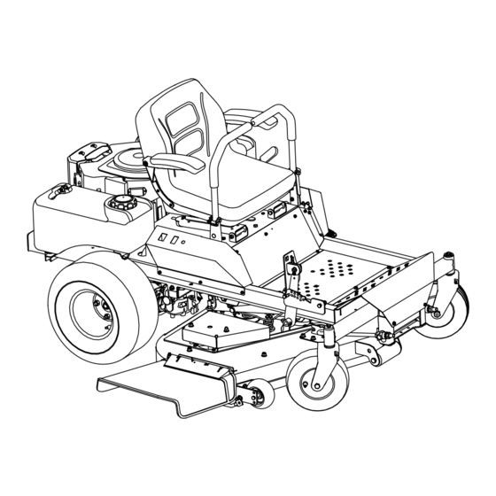
Cub Cadet Z-Force 48 Operator's Manual
Zero-turn tractor
Hide thumbs
Also See for Z-Force 48:
- Compatibility manual (3 pages) ,
- Brochure & specs (2 pages) ,
- Brochure (2 pages)
Table of Contents
Advertisement
Safe Operation Practices • Set-Up • Operation • Maintenance • Service • Troubleshooting • Warranty
O
'
M
peratOr
s
anual
Z-Force 48 & 54
WARNING
READ AND FOLLOW ALL SAFETY RULES AND INSTRUCTIONS IN THIS MANUAL
BEFORE ATTEMPTING TO OPERATE THIS MACHINE.
FAILURE TO COMPLY WITH THESE INSTRUCTIONS MAY RESULT IN PERSONAL INJURY.
CUB CADET LLC, P.O. BOX 361131 CLEVELAND, OHIO 44136-0019
Printed In USA
Form No. 769-08543
(October 15, 2012)
Advertisement
Table of Contents

Related Manuals for Cub Cadet Z-Force 48


Summary of Contents for Cub Cadet Z-Force 48
- Page 1 READ AND FOLLOW ALL SAFETY RULES AND INSTRUCTIONS IN THIS MANUAL BEFORE ATTEMPTING TO OPERATE THIS MACHINE. FAILURE TO COMPLY WITH THESE INSTRUCTIONS MAY RESULT IN PERSONAL INJURY. CUB CADET LLC, P.O. BOX 361131 CLEVELAND, OHIO 44136-0019 Printed In USA Form No. 769-08543...
-
Page 2: Table Of Contents
Visit us on the web at www.cubcadet.com See How-to Maintenance and Parts Installation Videos at www.cubcadet.com/tutorials ◊ Locate your nearest Cub Cadet Dealer at (877) 282-8684 ◊ Write to Cub Cadet LLC • P.O. Box 361131 • Cleveland, OH • 44136-0019... -
Page 3: Safe Operation Practices
Important Safe Operation Practices WARNING! This symbol points out important safety instructions which, if not followed, could endanger the personal safety and/or property of yourself and others. Read and follow all instructions in this manual before attempting to operate this machine. Failure to comply with these instructions may result in personal injury. - Page 4 A missing or damaged discharge cover can cause blade If situations occur which are not covered in this manual, use contact or thrown object injuries. care and good judgment. Contact your customer service representative for assistance. Stop the blade(s) when crossing gravel drives, walks, or roads and while not cutting grass.
- Page 5 Children • The fore/aft single-locking adjustment tracks operate on roller-bearings for smooth and almost effortless operation. Tragic accidents can occur if the operator is not alert to the The lever for seat track actuation is near the right front presence of children. Children are often attracted to the corner of the seat bottom, and allows fore/aft adjustment machine and the mowing activity.
-
Page 6: Spark Arrestor
General Service Do not change the engine governor settings or over-speed the engine. The governor controls the maximum safe Never run an engine indoors or in a poorly ventilated area. operating speed of the engine. Engine exhaust contains carbon monoxide, an odorless, Maintain or replace safety and instruction labels, as and deadly gas. -
Page 7: Safety Symbols
Safety Symbols This page depicts and describes safety symbols that may appear on this product. Read, understand, and follow all instructions on the machine before attempting to assemble and operate. Symbol Description READ THE OPERATOR’S MANUAL(S) Read, understand, and follow all instructions in the manual(s) before attempting to assemble and operate WARNING—... - Page 8 2 — S ection peration racticeS...
-
Page 9: Assembly & Set-Up
Assembly & Set-Up Contents of Crate • One Lawn Tractor • One Tractor Operator’s Manual • One Deck Wash Hose Coupler • One Engine Operator’s Manual Tractor Preparation Remove the two shoulder bolts, nuts and spacers securing the seat as shown in Figure 1-2. Remove the upper crating material from the shipping pallet, and cut any bands or tie straps securing the tractor to the pallet. - Page 10 Connecting the Battery Cables Install lanyard using existing self-tapping screw. See Figure 1-4. CALIFORNIA PROPOSITION 65 WARNING Battery posts, terminals, and related accessories contain lead and lead compounds, chemicals known to the State of California to cause cancer and reproductive harm. Wash hands after handling. Existing Self- CAUTION: When attaching battery cables, always...
- Page 11 Adjusting the Seat To adjust the position of the seat, pull up and hold the seat adjustment lever. Slide the seat forward or rearward to the desired position; then release the adjustment lever. Make sure seat is locked into position before operating the tractor. See Figure 1-7. Figure 1-7 2 —...
-
Page 12: Controls & Features
Controls & Features Storage Tray Cup Holder Throttle Control Choke Control SLOW FAST W A R N I N G START CHOKE ON NEUTRAL W A R N I N G BRAKE Parking Brake Fuel Shut-Off Valve RH Drive Fuel Tank Deck Lift Control Lever Pedal... - Page 13 Ignition Switch Throttle Control START The ignition switch is located on SLOW FAST the RH console to the right of the operator’s seat. The ignition switch has three positions as follows: The throttle control is located on the LH console to the left of the operator’s seat.
- Page 14 Fuel Shut-Off Valve Transmission Bypass Rods (Not Shown) The fuel shut-off valve is located on top of the fuel tank. When The transmission bypass rods (one for each the RH and LH turned in a clockwise direction until it stops, it will shut off the flow transmission) are located beneath the frame platform, just inside of fuel to the engine.
-
Page 15: Operation
Operation General Safety • Avoid driving too close to trees, creeks, ditches, sand traps, and other obstacles. • RECEIVE INSTRUCTION — Entirely read this operator’s • Slow down before turning and come to a complete stop manual. Learn to operate this machine SAFELY. Do not risk before any zero turn maneuver. -
Page 16: Safety Interlock System
If the interlock system should ever malfunction, do not operate the tractor. Contact your authorized Once the engine warms up, push the choke knob down Cub Cadet Dealer. into the OFF position. • The safety interlock system prevents the engine from... -
Page 17: Driving The Tractor
Driving the Tractor Stopping the Engine Place the PTO switch in the “OFF” position. WARNING! Avoid sudden starts, excessive speed Move the RH and LH drive control levers to the neutral and sudden stops. position. Engage the parking brake. Adjust the operator’s seat to the most comfortable Move the throttle control to midway between the SLOW position that allows you to operate the controls. - Page 18 Driving the Tractor Forward To turn to the left, move the left drive control lever rearward of the right lever. See Figure 1-3. WARNING! Keep all movement of the drive control levers slow and smooth. Abrupt movement of the control levers can affect the stability of the tractor and could cause the tractor to flip over, which may Forward Left Turn result in serious injury or death to the operator.
- Page 19 Driving the Tractor In Reverse Turning While Driving Rearward WARNING! To turn the tractor while driving rearward, move the control Always look behind and down on both levers as necessary so that one lever is forward of the other. The sides of the tractor before backing up.
- Page 20 Executing a Zero Turn Executing a “Y” Manuever WARNING! For low traction conditions, follow these procedures for zero When executing a zero turn, the turns (the “Y-manuever”): tractor MUST BE STOPPED. Executing a zero turn while the tractor is moving can significantly reduce To turn clockwise (front of machine moves toward RIGHT) when your control of the tractor and will cause severe turf traveling FORWARD:...
- Page 21 If a safety circuit is not working as designed, contact you Cub Cadet dealer to have the tractor inspected. DO NOT operate the tractor if any safety circuit is not functioning NOTE: Do not engage the mower deck when lowered in grass.
-
Page 22: Maintenance & Adjustment
Maintenance & Adjustments Maintenance Schedule Before Every Every Every Every After Mowing Each use 25 Hours 50 Hours 100 Hours 300 Hours Check Gasoline Level Check Hydraulic Transaxles for leaks Check Tires & Tire Pressure Check Deck, Mower and Hydro Drive Belts Check Blades and Blade Bolt Tightness Check Safety Switches for proper Operation Check Engine Intake Screen/Cover... - Page 23 OIL CHART Apply a few drops of SAE engine oil, grease, or use a spray lubricant. Apply the oil to both sides of pivot points. Wipe off any excess. Start engine and operate mower briefly to insure that oil spreads evenly. Number of Oil Points Description DAILY...
- Page 24 Maintenance Hydrostatic Transmission Your zero turn tractor is equipped with dual integrated WARNING! Before performing any maintenance or hydrostatic pumps/transaxles that are sealed and are repairs, disengage the PTO, move the drive control maintenance-free. However, this model is equipped with a levers fully outward in the neutral position, engage transmission oil expansion reservoir.
- Page 25 General Battery Information Using the Deck Wash System WARNING! WARNING! When using the deck wash system, never engage the deck from any position other than Should battery acid accidentally splatter into the operator’s seat of the tractor. Do not use an the eyes or onto the skin, rinse the affected area assistant or engage deck in the presence of any immediately with clean cold water.
- Page 26 Using the Transmission Bypass Rods Tractor Storage If for any reason the tractor will not drive or you wish to move the If your tractor is not going to be operated for an extended period tractor, the two hydrostatic transmissions are equipped with a of time (thirty days to approximately six months), the tractor bypass rod that will allow you to manually move the tractor short should be prepared for storage.
-
Page 27: Pivot Bracket
Sharpen the blades so that the mower will be ready to use To adjust the height of the drive control levers: when needed. Remove the nuts from the control lever mounting bolts. Protect the metal surfaces. Repair scratches with the See Figure 1-5. - Page 28 Brakes Measure blade-to-ground height at the front tip of the right blade. To obtain an accurate measure, align blades in NOTE: The parking brakes normally do not need to be adjusted. parallel with mower centerline, (i.e. front to back). To adjust either brake individually, loosen the jam nuts on the Measure blade-to-ground height at the front tip of the left cable near the brake arm on the transaxle.
- Page 29 Off-Season Storage Removing the Riding Mower from Storage Check the engine oil. Riding Mower Storage Fully charge the battery, lower riding mower off blocks, If your riding mower is not going to be operated for an extended and inflate the tires to the recommended pressure. period of time (thirty days to approximately six months), the riding Remove the spark plugs and wipe them off.
-
Page 30: Service
NEG). Move the cable away from the negative battery post. the electrical system checked by your Cub Cadet Service Dealer. Remove the hex cap screw and sems nut securing the red... -
Page 31: Replacing The Blades
Remove the four hair pins from the right and left side of the Remove the blade drive belt from all the pulleys. deck lift bracket. See Figure 1-3. Reverse the process to install the belt. See Figure 1-5 for proper belt routing. Deck Lift Bracket Hair Pin... - Page 32 Remove the blade. order to change the tractor’s transmission drive belt. See your To replace the blade reverse the above process and tighten Cub Cadet dealer to have the transmission drive belt replaced. nut to 100-120 lb ft. Tractor Creeping NOTE: Add a small amount of multi-purpose grease to the bolt threads to avoid corrosion and galvenic action.
-
Page 33: Troubleshooting
Troubleshooting Problem Cause Remedy Excessive vibration 1. Cutting blade loose or unbalanced. 1. Tighten blade and spindle. 2. Damaged or bent cutting blade. 2. Replace blade. Uneven cut 1. Deck not leveled properly. 1. Perform side-to-side deck adjustment. 2. Dull blade. 2. -
Page 34: Replacement Parts
Choke Cable (877) 282-8684 Phone to locate your nearest Cub Cadet dealer to order replacement parts or a complete Parts Manual (have your full model number and serial number ready). Parts Manual downloads are also available free of charge at www.cubcadet.com. - Page 35 (877) 282-8684 Phone to locate your nearest Cub Cadet dealer to order replacement parts or a complete Parts Manual (have your full model number and serial number ready). Parts Manual downloads are also available free of charge at www.cubcadet.com. 9 — R...
-
Page 36: Attachments & Accessories
Attachments & Accessories The following attachments and accessories are compatible with your Zero-Turn tractor. See your dealer or the retailer from which you purchased your tractor for information regarding price and availability. WARNING: Model 19A70030100 front-weight kit is required when operating any lap bar steering RZT model equipped with a compatible grass collector. - Page 37 Notes...
-
Page 38: Warranties
FEDERAL and/or CALIFORNIA EMISSION CONTROL WARRANTY STATEMENT YOUR WARRANTY RIGHTS AND OBLIGATIONS MTD Consumer Group Inc, the United States Environmental Protection Agency (EPA), and, for those products certified for sale in the state of California, the California Air Resources Board (CARB) are pleased to explain the emission (evaporative and/or exhaust) control system (ECS) warranty on your outdoor 2006 and later small off-road spark-ignited engine and equipment (outdoor equipment engine) In California, new outdoor equipment engines must be designed, built and equipped to meet the State’s stringent anti-smog standards (in other states, 1997 and later model year equipment must be designed, built, and equipped to meet the U.S. - Page 39 Add-on or modified parts that are not exempted by the Air Resources Board may not be used. The use of any non-exempted add-on or modified parts by the ultimate purchaser will be grounds for disallowing a warranty claims. MTD Consumer Group Inc will not be liable to warrant failures of warranted parts caused by the use of a non-exempted add-on or modified part.
- Page 40 Contact MTD Products Limited, Kitchener, ON N2G 4J1, call 1-800- The limited warranty set forth below is given by Cub Cadet LLC with 668-1238 or log on to our website at www.mtdcanada.com. respect to new merchandise purchased or leased and used in the...