Table of Contents
Advertisement
Operator's Manual
IMPORTANT: READ SAFETY RULES AND INSTRUCTIONS CAREFULLY
Warning
: This unit is equipped with an internal combustion engine and should not be used on or near any unimproved
forest-covered, brush-covered or grass-covered land unless the engine's exhaust system is equipped with a spark
arrester meeting applicable local or state laws (if any). If a spark arrester is used, it should be maintained in effective
working order by the operator. In the State of California the above is required by law (Section 4442 of the California Public
Resources Code). Other states may have similar laws. Federal laws apply on federal lands. A spark arrester for the
muffler is available through your nearest engine authorized service dealer or contact the service department, P.O. Box
361131 Cleveland, Ohio 44136-0019.
CUB CADET LLC P.O. BOX 361131 CLEVELAND, OHIO 44136-0019 [www.cubcadet.com]
PRINTED IN U.S.A.
S
ERIES
TRACTOR
MODEL 5252
5000
FORM NO. 769-00867I
(7/06)
Advertisement
Table of Contents

Related Manuals for Cub Cadet TRACTOR 5252


Summary of Contents for Cub Cadet TRACTOR 5252
- Page 1 Resources Code). Other states may have similar laws. Federal laws apply on federal lands. A spark arrester for the muffler is available through your nearest engine authorized service dealer or contact the service department, P.O. Box 361131 Cleveland, Ohio 44136-0019. CUB CADET LLC P.O. BOX 361131 CLEVELAND, OHIO 44136-0019 [www.cubcadet.com] PRINTED IN U.S.A. 5000...
-
Page 2: Table Of Contents
The dealer has trained service personnel familiar with the latest servicing information, is equipped with the latest tools, and has a complete line of genuine Cub Cadet service parts which assure proper fit and high quality. -
Page 3: Recording Model And Serial Number Information
Serial Number ROPS Information Plate: ROPS Serial No. TRACTOR MODEL PLATE XXXXXXXXXXX XXXXXXXXXX Model Number Mfg. Date CUB CADET LLC P. O. BOX 361131 www.cubcadet.com CLEVELAND, OH 44136 DEALER LOCATOR PHONE NUMBER: 877-282-8684 Mfg. Date (Serial No.) Spec. No. Serial No. -
Page 4: Important Safe Operation Practices
IMPORTANT SAFE OPERATION PRACTICES WARNING: THIS SYMBOL POINTS OUT IMPORTANT SAFETY INSTRUCTIONS WHICH, IF NOT FOLLOWED, COULD ENDANGER THE PERSONAL SAFETY AND/OR PROPERTY OF YOURSELF AND OTHERS. READ AND FOLLOW ALL INSTRUCTIONS IN THIS MANUAL BEFORE ATTEMPTING TO OPERATE YOUR UNIT. FAILURE TO COMPLY WITH THESE INSTRUCTIONS MAY RESULT IN PERSONAL INJURY. -
Page 5: Slope Operation
Debris may build up on the mower deck or contact the engine exhaust presenting a potential fire hazard. • only accessories approved machine by Cub Cadet. Read, understand and follow instructions provided approved accessory. • Use the roll bar and seat belt for safe operation. -
Page 6: Operating The Pto
3. CHILDREN • Tragic accidents can occur if the operator is not alert to the presence of children. Children are often attracted to the machine. Never assume children will remain where you last saw them. • Keep children out of the mowing area and in watchful care of an adult other than the operator. - Page 7 • Keep all nuts, bolts and screws tight to be sure the equipment is in safe working condition. • Never tamper with safety devices. Check their proper operation regularly. • After striking a foreign object, stop the engine, and thoroughly inspect the mower for any damage.
-
Page 8: Safety Labels
SAFETY LABELS WARNING AVOID SERIOUS INJURY OR DEATH GO UP AND DOWN SLOPES, NOT ACROSS. AVOID SUDDEN TURNS. DO NOT OPERATE UNIT WHERE IT COULD SLIP OR TIP. IF MACHINE STOPS GOING UPHILL, STOP PTO AND BACK DOWN HILL SLOWLY. DO NOT MOW WHEN CHILDREN OR OTHERS ARE AROUND. -
Page 9: Section 1: Controls And Features
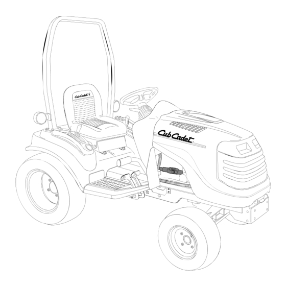
SECTION 1: CONTROLS AND FEATURES Steering Wheel Throttle Handle PTO Switch Ignition Switch Brake Pedal Reverse Pedal G. Forward Pedal * Steering Wheel, Seat, and ROPS Transparent for Clarity HOURS 1/10 FUEL x1000 Figure 1 Hand Holds Hydraulic Lift Lever Cup Holder Amber Hazzard Light Seat Adjustment Lever... - Page 10 NOTE: References to LEFT and RIGHT indicate that side of the tractor when facing forward while seated in the drivers seat. Reference to FRONT indicates the grille end of the tractor; to REAR, the tow plate end. A. Steering Wheel The steering wheel is centered on the dash panel, and used to change the direction (left or right) of the tractor while driving.
- Page 11 G. Forward Pedal Forward Pedal Symbol Figure 6 The forward control pedal is located on the right running board below the brake pedal. Slowly press down on the pedal to start moving forward. The forward ground speed of the tractor is directly affected by the distance the pedal is depressed.
- Page 12 S. Differential Lock Pedal Diff. Lock Pedal Symbol Figure 8 Located at the front of the left running board, the differential lock pedal engages the transmission differential lock. The differential lock is used to gain additional trac- tion when operating the tractor on wet or loose soil. When the pedal is depressed the rear wheels of the tractor are prevented from rotating independently of one another.
- Page 13 If the oil level is within the operating range, but the light remains on, contact your Cub Cadet dealer. NOTE: The oil pressure indicator may illuminate when the key switch is turned to the on position, but should turn off when the engine is started.
-
Page 14: Section 2: Operation
• In the event of an accident, have the ROPS carefully inspected and, if necessary, replaced by your Cub Cadet dealer. Do not attempt to repair the ROPS. MODELS EQUIPPED WITH A FOLDING ROPS The foldable ROPS feature allows the operator to quickly lower the ROPS to operate in areas where there is low overhead clearance. - Page 15 If the interlock system should ever malfunction, do not operate the tractor. Contact your authorized Cub Cadet Dealer. The safety interlock system prevents the engine from cranking or starting unless the brake pedal is fully depressed, and the PTO is “OFF”.
- Page 16 If the noise continues, increase the engine speed to mid-throttle and allow the engine to run for several minutes. If the noise persists, contact your Cub Cadet dealer. WARNING: If the starter disengages the engine flywheel, but the engine does...
- Page 17 DRIVING THE TRACTOR WARNING: Avoid sudden starts, exces- sive speed and sudden stops. WARNING: Do not leave the seat of the tractor without disengaging the PTO and engaging the parking brake. If leaving the tractor unattended, turn the ignition key off and remove key. •...
- Page 18 USING THE HI/LO RANGE SHIFT LEVER WARNING: tractor stopped before engaging or disengag- ing the transmission Hi/Lo range shift lever. Shifting while the tractor is in motion will cause damage to the transmission. WARNING: Always maintain a tractor speed that allows for complete control and stability of the machine.
- Page 19 • Fully depress and hold the differential lock pedal to engage the transmission differential lock. Release the pedal to disengage the differential lock. See Figure 18. DIFFERENTIAL LOCK PEDAL (Depress and Hold to Engage) Figure 18 NOTE: Because of the drive load on the internal engagement mechanism, releasing the differential lock pedal...
- Page 20 USING THE PTO REVERSE OVERRIDE SWITCH The PTO reverse override switch, located on the left fender, allows the PTO to operate while the tractor is traveling in the reverse direction. See Figure 21. PTO REVERSE OVERRIDE SWITCH Figure 21 • The PTO should first be engaged using the PTO switch on the dash panel.
- Page 21 REMOVING THE REAR PTO COVER The rear PTO cover is a safety feature designed to prevent items from accidentally being caught by the rotating shaft. The cover should be removed only when the rear PTO is being utilized. To remove and reinstall the cover, proceed as follows: •...
- Page 22 To counterbalance three point hitch mounted equipment, a weight bracket/bumper kit and cast iron weights are available from your Cub Cadet dealer. Refer to the Weighting Table for the proper ballast to be added to the front of the tractor.
-
Page 23: Section 3: Adjustments
SECTION 3: ADJUSTMENTS ADJUSTING THE SEAT For the comfort of the operator, a single lever adjustable seat is provided to set the fore to aft position of the seat. Adjust the seat to the most comfortable position that allows you to operate all controls and pedals. - Page 24 • The length of the upper hitch link is normally determined by the design of each implement. To adjust the upper hitch link, loosen the lock- ing lever and turn the adjustment tube as shown in Figure 28. After the appropriate length is attained, tighten the locking lever.
- Page 25 ADJUSTING THE BRAKES The tractor brakes are adjusted at the factory and should experience minimal wear if the tractor is operated normally. However, all brake pads are subject to wear and at some point the brake linkage may have to be adjusted. Check the brakes as follows: •...
-
Page 26: Section 4: Tractor Maintenance
20 Qts. (5.0 Gal.) Needed 737-3034 (14.5 Oz. Cartridge) Description Viscosity 5W-20 † Use High 5W-30 † Quality Engine Oil Cub Cadet 10W-30 † 737-3030A (1Qt.) Use Cub Cadet 737-3120 (1 Qt.) 737-3121 (1 Gal.) Use Cub Cadet 251H EP Grease... - Page 27 LUBRICATION AND MAINTENANCE CHART (ILLUSTRATION)
-
Page 28: Lubrication And Maintenance Chart
LUBRICATION AND MAINTENANCE CHART Ref. Operation to be Performed Check Engine Oil Level Check Air Cleaner Clean Air Cleaner Foam Precleaner Element Change Engine Oil and Replace Oil Filter Retorque Front Wheel Lug Bolts and Rear Wheel Lug Nuts Check Transmission Oil Level Replace Hydrostatic Transmission Oil Filter Replace Hydraulic System Filter... - Page 29 ACCESSING THE ENGINE COMPARTMENT WARNING: If the tractor has been recently operated, engine surfaces will be HOT. Allow the engine to cool before opening the hood, or use extreme caution to avoid burns when the hood is open. Locate the hood notch at the front of the tractor. Depending on which type of hood latch is installed on your tractor, raise the hood as follows: •...
- Page 30 • Loosen the cable clamp of the black negative battery lead, then lift the negative cable and its terminal cover off the negative battery post (marked NEG). Move the cable away from the negative battery post. • Repeat the above procedure to remove the cable and cover from the positive battery post (marked POS).
- Page 31 Figure 37 If you have a recurring problem with blown fuses, have the tractor’s electrical system checked by your Cub Cadet dealer. Main Fuse The main fuse in the tractor wire harness protects the tractor’s entire electrical system. A blown main fuse will prevent battery current from passing though the harness.
- Page 32 Tractors with Electric Fuse Center Instrument Panel Fuses The instrument panel’s circuitry is protected by the two fuses in the fuse center. If the instrument panel does not function properly, check the fuses. Pull the two fuses from the fuse center and check their condition.
-
Page 33: Checking Transmission/Hydraulic System Oil Level
Insert a funnel (preferably one with a flexible spout) into the fill hole of the transmission housing. • Add Cub Cadet Drive System Plus oil until the oil level can be seen through the sight glass. Do not overfill the transmission. IMPORTANT: Always use Cub Cadet Drive System Plus oil to ensure correct formulation. - Page 34 • Remove the old hydrostatic filter by turning it counterclockwise, and immediately replace with the new filter. Turn the filter clockwise by hand until the gasket contacts the filter base; then tighten the filter an additional 1/2 to 3/4 turn. •...
- Page 35 • Pour Cub Cadet Drive System Plus oil into the transmission housing until the oil level can be seen through the sight glass. Do not overfill the transmission.
- Page 36 PROTECTIVE STRUCTURE (ROPS) Periodically (at least every six months) visually inspect the ROPS for damage and loose fasteners. If damage is noted, contact your Cub Cadet dealer. If an accident has occurred which may have damaged the ROPS, have the ROPS thoroughly inspected by your Cub Cadet dealer.
- Page 37 Emptying the fuel system: • Prior to putting the tractor in storage, monitor fuel consumption with the goal of running the fuel tank empty. • If a large volume of fuel is left-over, the fuel line can be disconnected at the fuel filter and the leftover fuel drained into an approved container.
-
Page 38: Section 5: Engine Information And Maintenance
SECTION 5: ENGINE INFORMATION AND MAINTENANCE FEDERAL AND CALIFORNIA EMISSION CONTROL SYSTEMS SMALL OFF-ROAD EQUIPMENT ENGINES The U.S. Environmental Protection Agency (EPA), the California Air Resources Board (CARB), and Kohler Co. are pleased to explain the Federal and California Emission Control Systems Warranty on your small off-road equipment engine. For California, engines produced in 1995 and later must be designed, built and equipped to meet the state’s stringent anti-smog standards. - Page 39 ENGINE MAINTENANCE WARNING: Use care when servicing any component in the engine area. If the engine has recently been operated, components will be hot and could cause burns. Allow the engine to cool before servicing. WARNING: Before servicing the engine, place the tractor on a level surface, stop the engine, engage the parking brake, and remove the key from the...
- Page 40 CHANGING THE ENGINE OIL AND FILTER WARNING: Because the engine is run prior to draining the oil, the engine may be hot. Use caution to avoid burning yourself on engine surfaces. The engine oil and oil filter should be changed after every 100 hours of operation.
- Page 41 SERVICING OIL COOLER - IF EQUIPPED Inspect and clean the oil cooler, located next to the oil filter, after every 100 hours of operation. Clean debris from the fins of the oil cooler with a brush or using compressed air. See Figure 50. OIL COOLER Figure 50 CHECKING THE AIR CLEANER...
- Page 42 • Slip the precleaner fully onto the paper ele- ment and reinstall the paper element onto the air cleaner base. • Install the element cover and secure with the wing nut. • Reinstall the air cleaner cover and secure with the retainer knob.
-
Page 43: Section 6: Mower Deck
SECTION 6: MODELS WITH FACTORY INSTALLED 60" MOWER DECK This section applies only to those models with the factory equipped 60 inch mower deck. Skip this section and refer to your mower deck Owner’s Manual for all other models. DECK LEVELING ADJUSTMENTS The 60"... - Page 44 Front To Back Leveling The front to back pitch of the deck is normally determined by the deck wheels when the deck is operated as designed with its wheels on the ground. However, the deck pitch should be checked to ensure an even cut when mowing uneven terrain, or when mowing with the deck wheels off the ground.
- Page 45 SETTING THE CUTTING HEIGHT The deck cutting height is set by positioning the left and right caster wheel axles in one of the five index hole settings of the deck height adjustment bracket. The index hole settings range in 1/2 inch increments from a cutting height of approximately 1-1/2 inches (top hole) to 3-1/2 inches (bottom hole).
- Page 46 INTERNAL COTTER PIN CHECK CHAIN Figure 61 • Disconnect the fixed link from the RH lift arm by removing the internal cotter pin and clevis pin. Reinstall the clevis pin and internal cotter pin in the fixed link to avoid their loss. See Figure 62. INTERNAL COTTER PIN CLEVIS PIN...
- Page 47 INTERNAL COTTER PIN REAR DECK CLEVIS PIN WHEEL Figure 65 • From the right side of the tractor, grasp the fixed link and make certain it is clear of the right lift arm. Refer to Figure 62. • Holding the fixed link upward, maneuver the fixed link between the tire and fender while sliding the deck out from beneath the right side of the tractor.
- Page 48 DECK MAINTENANCE Cleaning And Blade Care Use the Deck Wash System as follows: WARNING: When using the deck wash, never engage the deck from any position other than the operator’s seat of the trac- tor. Do not use an assistant or engage deck in the presence of bystanders.
- Page 49 3&4 SPINDLE BELT REPLACEMENT A worn spindle belt will affect the quality of cut from the mower deck and should be replaced. Referring to Figure 69 and Figure 70, replace the spindle belt as follows: Remove Spindle Belt • Remove the hex cap screws securing the LH belt cover to the deck.
- Page 50 Install New Spindle Belt 1. Lift the gear box/mounting bracket assembly to install the belt around the rear of the drive pulley and through the center opening of the mounting bracket. 2. Position the gear box mounting bracket on the deck mounting plate and secure with the four hex cap screws and hex flange lock nuts.
- Page 51 MOWER DECK LUBRICATION GUIDE NOTE: We do not recommend the use of a pressure washer or garden hose to clean your unit. They may cause damage to spindles; pulleys; or bearings. The use of water will result in shortened life and reduce serviceability.
-
Page 52: Section 7: Specifications
MOWING WARNING: To avoid possible injury, never direct the discharge of material toward bystanders or allow anyone near the machine while in operation. Although the area has been supposedly cleared of foreign objects, small objects may be picked up and discharged by the mower. For best results it is recommended that the first two laps should be cut with the discharge thrown towards the center. -
Page 53: Specifications
Oil ........ -
Page 54: Section 8: Optional Equipment And Accessories
When purchasing your tractor, you likely had it equipped for your particular needs at the time. You may wish to obtain additional equipment or accessories to perform other tasks. Refer to the table below for a list of optional equipment and accessories currently available through your Cub Cadet dealer. DESCRIPTION Front Hitch Kit 54"... -
Page 55: Warranty Statements
CALIFORNIA EMISSION CONTROL WARRANTY STATEMENT The California Air Resources Board and MTD Consumer Group Inc are pleased to explain the evaporative emission control system warranty on your 2006 lawn mower. In California, new lawn mower must be designed, built and equipped to meet the State’s stringent anti-smog standards. MTD Consumer Group Inc must warrant the EECS on your lawn mower for the period of time listed below provided there has been no abuse, neglect or improper maintenance of your lawn mower. -
Page 56: Cub Cadet Llc
Contact MTD Products Limited, Kitchener, ON N2G 4J1, or call 1-800-668-1238 or log on to our Web site at www.mtdcanada.com. Cub Cadet LLC at P.O. Box 361131, Cleveland, Ohio 44136-0019, or call 1-877-282- 8684, or MTD Canada Ltd. KITCHENER, ON N2G 4J1; Phone 1-800-668-1238...