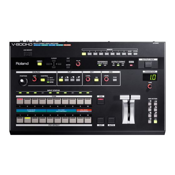
Roland V-800HD Owner's Manual
Multi-format video switcher
Hide thumbs
Also See for V-800HD:
- Specifications (4 pages) ,
- Brochure & specs (8 pages) ,
- Reference manual (20 pages)
Table of Contents
Advertisement
Owner's Manual
Before using this unit, carefully read the sections entitled: "IMPORTANT SAFETY INSTRUCTIONS" (p.2),
"USING THE UNIT SAFELY" (p. 3), and "IMPORTANT NOTES" (p. 5). These sections provide important
information concerning the proper operation of the unit. Additionally, in order to feel assured that you
have gained a good grasp of every feature provided by your new unit, owner's manual should be read in
its entirety. The manual should be saved and kept on hand as a convenient reference.
Copyright © 2012 ROLAND CORPORATION
All rights reserved. No part of this publication may be reproduced in any form without the written
permission of ROLAND CORPORATION.
* Roland is either registered trademark or trademark of Roland Corporation in the United States and/or other countries.
* All product names mentioned in this document are trademarks or registered trademarks of their respective owners.
Advertisement
Table of Contents

Related Manuals for Roland V-800HD


Summary of Contents for Roland V-800HD
- Page 1 All rights reserved. No part of this publication may be reproduced in any form without the written permission of ROLAND CORPORATION. * Roland is either registered trademark or trademark of Roland Corporation in the United States and/or other countries. * All product names mentioned in this document are trademarks or registered trademarks of their respective owners.
-
Page 2: Important Safety Instructions
WARNING: To reduce the risk of fire or electric shock, do not expose this apparatus to rain or moisture. The lightning flash with arrowhead symbol, within an CAUTION equilateral triangle, is intended to alert the user to the RISK OF ELECTRIC SHOCK presence of uninsulated dangerous voltage within the DO NOT OPEN product s enclosure that may be of sufficient magnitude to... -
Page 3: Using The Unit Safely
• When using the unit with a rack or stand recommended by Roland, the rack or stand must be carefully placed so it is • If smoke or unusual odor occurs level and sure to remain stable. If not using a rack or stand, •... - Page 4 Before using the unit in a foreign country, consult with your ..............................retailer, the nearest Roland Service Center, or an authorized Avoid climbing on top of the unit, or placing heavy objects on it. Roland distributor, as listed on the “Information” sheet.
-
Page 5: Important Notes
Do not use this unit to create Depending on the way in which the electrical appliance is used, power video that might cause these types of health problems. Roland Corpo- supply noise may cause this unit to malfunction or may produce ration will accept no responsibility for any such health problems that audible noise. -
Page 6: Table Of Contents
Contents Check the Included Items................8 About the Multi-view Monitor ...............9 Connecting the Monitor............................9 Selecting an Output Format for the Multi-view Monitor ................. 9 About the Menu Displays ............................ 9 About the Display on the Multi-view Monitor ...................10 About Power Supply..................11 About the Ground Terminal..........................11 About the Cord Hook ............................12 Turning the Power On and Off.........................13... - Page 7 Menu Operations ..................51 Appendices....................52 Main Specifications ..............................52 Name Plate ................................52 About Remote Control............................53 About Rack Mounting ............................53 About the Input Template..........................53 Troubleshooting..............................54 Dimensions ................................55 V-800HD Version 1.50 Added Functions........... 56 Index ......................60...
-
Page 8: Check The Included Items
MMP (Moore Microprocessor Portfolio) refers to a patent portfolio concerned with microprocessor architecture, which was developed by Technology Properties Limited (TPL). Roland has licensed this technology from the TPL Group. -
Page 9: About The Multi-View Monitor
HDMI Selecting an Output Format for the Multi-view Monitor You can select an output format for the monitor connected to the V-800HD. Depending on the monitor you are using, select one from below. Output Y/Cb/Cr signal Hold down [1] of the MEMORY buttons and turn the power on. -
Page 10: About The Display On The Multi-View Monitor
About the Multi-view Monitor About the Display on the Multi-view Monitor When the source device is connected to the V-800HD and turned on, the output video and the source video are displayed as shown below. fig.multi-view.eps CH 1 CH 2... -
Page 11: About Power Supply
(see figure) with an external ground. When the unit is grounded, a slight hum may occur, depending on the particulars of your installation. If you are unsure of the connection method, contact the nearest Roland Service Center, or an authorized Roland distributor, as listed on the “Information”... -
Page 12: About The Cord Hook
About Power Supply About the Cord Hook Secure the power cord in place using the cord hook as shown below. This can help prevent power loss due to the plug being pulled out if the power cord is accidentally yanked. Connect the power cord to the AC IN connector. -
Page 13: Turning The Power On And Off
* When still images are saved to the internal memory, booting of this unit will take longer because of preparations. Connect the peripheral devices. Connect video cameras or other equipment. Make the connections while the power to all equipment, including the V-800HD, is turned off. -
Page 14: Part Names And Functions
* Open the sliding cover only when you are using the USB port. When this is not in use, be sure to keep the sliding cover closed to protect the connector inside. Setup Section Use these menu controls to change settings on the V-800HD. Scaling Section You can zoom in/out the screen or adjust the display location. When you are applying Picture-in-Picture, you can use controls in this section to adjust the display location and size of the inset screen (p. - Page 15 The indicator flashes when the V-800HD cannot synchronize with the external device. • OUTPUT FORMAT This indicates the output format (p. 26) of the V-800HD. The corresponding combinations of the SD, HD, and RGB indicators are as follows. 480i, 576i...
-
Page 16: Rear Panel
15 16 POWER Switch This turns the power to the V-800HD on and off. MIDI IN and OUT/THRU Connectors You can use these when you remote control the unit from an external MIDI device (a device compatible with MIDI VISUAL CONTROL or the like), or when using the unit to perform remote control of another device. - Page 17 Connect an external source device for synchronization to the REFERENCE IN connector. When supplying a synchronizing signal to an external device via the V-800HD, use the REFERENCE THRU connector. * For information on using an external source device for synchronizing, refer to “Connecting a Clock Source” (p. 24).
-
Page 18: Signal Flow
Part Names and Functions Signal Flow The internal signal flow of the V-800HD is as shown below. fig.signal-flow.eps Composite Composite Composite Composite DVI-I/HDMI DVI-I/HDMI DVI-I/HDMI DVI-I/HDMI RGB/ RGB/ RGB/ RGB/ Component Component Component Component Shared Shared Shared Shared Shared Shared... -
Page 19: Connecting External Equipment
1600x1200/60 Hz, 1920x1200/60 Hz (Reduced Blanking), 480/59.94i, 576/50i, 480/59.94p, 576/50p, 720/59.94p, 720/50p, 1080/ 59.94i, 1080/50i, 1080/59.94p, 1080/50p Composite 480/59.94i, 576/50i The V-800HD automatically detects the input format. For information on output format, refer to “Selecting the Output Format” (p. 26). -
Page 20: Connecting Source Equipment
You can connect 3G-SDI, HD-SDI or SD-SDI source equipment to the SDI IN connectors. If a signal is input that has an aspect ratio different form the V-800HD’s output format, the image fills the screen at the output (default setting). You can also use the menus (p. 51) to select Letterbox, Crop, or Squeeze. - Page 21 Connecting External Equipment Connecting source equipment to a COMPOSITE IN connector requires changing the setting on the V-800HD. Use the procedure described below to change the source from SDI to composite. Display the Input menu. Press the [MENU] button to display the menu. Use the [CURSOR] buttons to select [Input], then press the [ENTER] button to display the Input menu.
-
Page 22: Connecting A Computer Or Hdmi Equipment
* For equipment capable of HDMI output, make the connection using a conversion cable. By default, the V-800HD does not support HDCP (High-bandwidth Digital Content Protection). When inputting video to which HDCP is applied, refer to “Inputting HDCP Signals” (p. 29) and change the settings on the V-800HD. - Page 23 Connecting External Equipment Connecting source equipment to RGB/COMPONENT IN connectors requires changing a setting on the V-800HD. Use the procedure described below to change the source from DVI to RGB/Component. Display the Input menu. Press the [MENU] button to display the menu. Use the [CURSOR] buttons to select [Input], then press the [ENTER] button to display the Input menu.
-
Page 24: Connecting A Clock Source
The V-800HD supports the external clocks shown below. To synchronize with an external clock, select [Reference] in System menu and set the value to [External]. • Black burst (frame synchronization) • Bi-level synchronization, tri-level synchronization The composite output from SD OUT jack always synchronizes to the V-800HD's internal clock regardless to the setting of [Reference] parameter. -
Page 25: Connecting Output Equipment
* NTSC or PAL video is output from the SD OUT connector, irrespective of the setting for output format on the V-800HD. fig.connect-recorder.eps When HDCP is set to [ON] (p. 29), output from the V-800HD will be DVI-D/HDMI signal only. The HDCP will be applied to DVI-D/HDMI only. Tally Output The V-800HD is equipped with two D-Sub 15-pins TALLY connectors. -
Page 26: Selecting The Output Format
Selecting the Output Format When the procedure in “Inputting HDCP Signals” (p. 29) has been followed to set the HDCP mode to [ON], output from the SDI OUT, SD OUT, and RGB/COMPONENT OUT connectors will be stopped. Note, however, that HDCP-applied output from the DVI-D/HDMI OUT connectors and output to the multi-view monitor will continue. - Page 27 Selecting the Output Format Changing the Format of the Main Output This changes the output format of the SDI OUT connectors and DVI-D/HDMI OUT connectors. This setting is shown by the [OUTPUT FORMAT] indicators. Display the Output menu. Press the [MENU] button to display the menu. Use the [CURSOR] buttons to select [Output], then press the [ENTER] button to display the Output menu.
- Page 28 * Output from the SD OUT connector is always 480/59.94i or 576/50i, irrespective of the setting for output format. About the Setting for the Output Source On the V-800HD, you can select PGM, PVW, or AUX as the output source. Display the Output menu and select an output connector. Then you can select [PGM], [PVW] or [AUX].
-
Page 29: Inputting Hdcp Signals
Inputting HDCP Signals By default, the V-800HD does not support HDCP (High-bandwidth Digital Content Protection). This means that HDCP-applied signals from Blu-ray Disc players and the like cannot be input. When inputting signals to which HDCP is applied, follow the procedure shown below to change the setting. - Page 30 Inputting HDCP Signals About the HDCP Indicator The [HDCP] indicator on the top panel operates as described below. • It lights up when an HDCP compatible device is connected as the output device. • It flashes when nothing is connected or when the connected device is not compatible with HDCP. •...
-
Page 31: Basic Operations
Basic Operations Using Buttons to Switch the Video Applying Transition Effects Using the [AUTO] button, you can apply transition effects during video switching. The transition effects are applied according to the settings of transition time and wipe pattern. Move the video fader all the way. Before the transition, move the video fader all the way toward either the front or the back. - Page 32 Basic Operations Select the channel you want to output next (standby). Use the cross-points on the [PST/EFFECT] side to choose the channel you want to output next. Pressing the button makes it light up in green. On the multi-view monitor, the selected channel is displayed with a green border around it. The video on the selected channel is also displayed in the [PVW] section.
-
Page 33: Using The Fader To Switch The Video
Basic Operations Using the Fader to Switch the Video When you use the [AUTO] button to switch, the transition effect is applied according to the setting of transition time. Using the video fader, you can control the transition time manually. Move the video fader all the way. -
Page 34: Applying Fade To Final Output
Basic Operations Applying Fade to Final Output You can use the [OUTPUT FADE] button to apply a fade to the final output of the V-800HD. Applying a fade makes the output video gradually disappear (fade-out) or appear (fade-in). fig.output-fade.eps Apply a fade-out. -
Page 35: Compositing The Video
Compositing the Video Picture-in-Picture (PinP) This displays an inset screen superimposed upon a background picture. Use the dial and joystick of the SCALING section to adjust the size and position of the inset screen. Luminance Key/Chroma Key/External Key (KEY) This performs compositing with a key-extracted video superimposed upon a background video. Use the [LEVEL] dial to adjust the amount of keying. - Page 36 Making a second press of the [PinP] button you pressed in step 3 also makes the inset screen disappear. You can use the menus to move the displayed position inside the inset screen. For information on the details of menus and their items, download “Reference Manual” from the following Roland website. http://www.rolandsystemsgroup.net/...
-
Page 37: Compositing Using Luminance/Chroma Key
Compositing the Video Compositing Using Luminance/Chroma Key You can perform compositing using luminance key or chroma key. * By default, black extraction is applied. You can select a different color using the menus (p. 51). fig.key-image.eps Black or White Blue or Green Luminance Key Chroma Key Select the background channel. - Page 38 Compositing the Video Adjust the amount of keying. While viewing the preview, turn the [LEVEL] dial in the KEY section to adjust the amount of keying. * You can use the menus to change the degree of edge blur. At the Key menu, adjust [Gain]. Also, when you are using chroma key, you can use [Hue] to adjust the extraction color.
-
Page 39: Compositing Using Dsk
Compositing the Video Compositing Using DSK By default, channel 8 is set as the source for the DSK. Also, by default, the unit is set to extract black. A white logo or text on black background can be extracted clearly. * You can change the DSK source channel or extraction color using the menus (p. - Page 40 Compositing the Video Output the composited results. Press the [DSK] button to output the results of compositing. The logo or text fades in. The fade time depends of your setting of transition time. fig.DSK-button.eps Switch the background picture. You can change the background picture while continuing to display a logo or text unchanged. Use the buttons on the [PST/ EFFECT] side to select the standby video, then use the [AUTO] or [CUT] button or the video fader to change the background picture.
-
Page 41: About Other Features
Using the [SIZE] dial in the SCALING section, you can enlarge or reduce the view of the picture. You can also use the [POSITION] joystick to change the display position. * On the V-800HD, you can enlarge or reduce the picture within a range of 10% to 1,000%. Enlarging/Reducing the Source Picture Put the picture you want to enlarge or reduce into standby. -
Page 42: Changing The Multi-View Labels
About Other Features Changing the Multi-view Labels You can change the text strings for channel names and the like displayed on the multi-view monitor. Up to 8 characters of text can be displayed. Display the System menu. Press the [MENU] button to display the menu. Use the [CURSOR] buttons to select [System], then press the [ENTER] button to display the System menu. -
Page 43: Saving Settings To Memory Buttons
Saving Settings to MEMORY Buttons You can save the current settings to a MEMORY button. The V-800HD’s internal memory contains banks from 1 to 8, and up to 8 sets of settings can be saved in each bank, for a total of up to 64. -
Page 44: Using A Usb Memory Device
About Other Features Using a USB Memory Device Connecting and Formatting a USB Memory Device Carefully insert the USB memories all the way in-until it is firmly in place. fig.connect-USB-memory.eps * Open the sliding cover only when you are using the USB port. When this is not in use, be sure to keep the sliding cover closed to protect the connector inside. -
Page 45: Saving Settings On A Usb Memory Device
Saving Settings on a USB Memory Device You can copy data saved in the V-800HD’s internal memory to a USB memory device formatted on the V-800HD. A batch copy of all data in internal memory from 1-1 to 8-8 is carried out at this time. -
Page 46: Using Still-Image Files
Using Still-image Files On the V-800HD, you can use still-image files in the ways described below. To use a still-image file, first import it into the V- 800HD’s internal memory. Direct output from a USB memory device is not possible. - Page 47 About Other Features Display the menu for loading still images. At [USB Memory], select [Still Image], then press the [ENTER] button. * If the target menu is not displayed, press the left or right [CURSOR] button to change the page. fig.USB-memory-menu.eps Select the assignment destination for the still image.
-
Page 48: Creating A Still Image From Final-Output Video
About Other Features Creating a Still Image from Final-output Video You can create a still image from the V-800HD’s output video and save it to internal memory (Output Capture). * The created still image cannot be saved to a USB memory device. -
Page 49: Changing Cross-Points
About Other Features Changing Cross-Points You can assign a source channel to any cross-point button ([1] through [10]). You can also cancel the assignments and disable button operations. fig.cross-point-concept.eps Ch.1 Ch.2 Ch.3 Ch.4 Ch.5 Ch.6 Ch.7 Ch.8 Ch.9 Ch.10 Ch.1 Ch.2 Ch.3 Ch.4... -
Page 50: Returning To The Factory-Default State
About Other Features Returning to the Factory-default State This returns various settings to their factory defaults. If following the instructions for a procedure results in operation that differs from what is described in the Owner’s Manual, execute a factory reset. * Executing a factory reset causes all setting values saved up to then to be lost. -
Page 51: Menu Operations
Menu Operations The V-800HD’s setting menus are displayed on the multi-view monitor. Menu operations follow the flow described below. For information on the details of menus and their items, download “Reference Manual” from the following Roland website. http://www.rolandsystemsgroup.net/ Display the menu. -
Page 52: Appendices
Appendices Main Specifications fig.specification-E.eps Video Processing Output Connectors Processing Analog Video Y:Pb:Pr, 4:4:4, 10 bits Composite (BNC type) x 1 Component (HD DB-15 type) x 1 480/59.94i, 576/50i, Supported Video * Combined use with Analog RGB 480/59.94p, 576/50p Formats * Progressive only 720/59.94p, 720/50p HD DB-15 type x 1 1080/59.94i, 1080/50i... -
Page 53: About Remote Control
• Never use any screws except the removed ones to block the screw holes. Using other screws may cause malfunction. • When installing the rack-mount angles, turn off the power to the V-800HD and detach the power cord and all connection cables. Also, be sure to install using the original screws. -
Page 54: Troubleshooting
Still-image data cannot be imported. Is the data of a format and size that the V-800HD can recognize (p. 46)? Also, data cannot be recognized unless the file name contains no more than eight single-byte alphanumeric characters and the file extension (.bmp) is present. -
Page 55: Dimensions
Appendices Dimensions fig.dimensions.eps 445.1 Unit : mm 115.9... -
Page 56: V-800Hd Version 1.50 Added Functions
Internal, External, Input SDI 1, ... Input SDI 4 • The output vsync of the V-800HD synchronizes with the input signal when the value of System -> Reference is Input SDI 1, ... Input SDI 4. In this case, the system latency is minimized. If you want to synchronize the input/output fields, execute the settings below. - Page 57 - Wipe setup - Input connector selection Automatic Memory Save • If this is turned on, the current status of the V-800HD is saved to memory 1-1 automatically. The status is loaded at next booting and the status returns. Menu Items Setting Value System ->...
- Page 58 Supports Multi-view monitor not compatible with HDCP • As the multi-view monitor, now you can connect HDCP non-compatible product. • However, of HDCP of the V-800HD is turned on, the multi-view screen is filled with plain blue. It can display the menu screen only.
-
Page 60: Index
Index AUTO ....................15 Scaling ....................14 SDI ....................19–20 Setup ....................14 Sharing ..................... 24 chroma key ..................37 Source Monitors ................9 Clock Source .................. 24 Still-image ..................46 Component ................19, 22 Composite ................19–20 Compositing ................14, 35 cord hook .................. -
Page 61: Federal Communications Commission
For EU Countries This product complies with the requirements of EMCD 2004/108/EC and LVD 2006/95/EC. For the USA FEDERAL COMMUNICATIONS COMMISSION RADIO FREQUENCY INTERFERENCE STATEMENT This equipment has been tested and found to comply with the limits for a Class A digital device, pursuant to Part 15 of the FCC Rules. - Page 62 For EU Countries For EU Countries This product is intended for use in the following Electromagnetic environments: E1: residential, E2: commercial and light industrial, E3: urban outdoors, E4: controlled EMC environment, ex. recording studio (broadcasting studio) which are specified in EN55103-1 and EN55103-2.