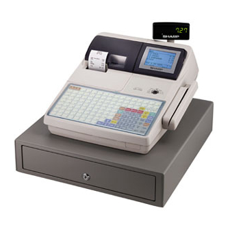
Sharp UP-600 Service Manual
Sharp up-600 cash register service manual
Hide thumbs
Also See for UP-600:
- Instruction manual (230 pages) ,
- Service manual (83 pages) ,
- Programming manual (51 pages)
Table of Contents
Advertisement
CHAPTER 1. SPECIFICATIONS ................................................................1 - 1
CHAPTER 2. OPTIONS ..............................................................................2 - 1
CHAPTER 3. SERVICE PRECAUTION ......................................................3 - 1
CHAPTER 4. SRV. RESET AND MASTER RESET ....................................... 4 - 1
CHAPTER 5. DIAGNOSTICS SPECIFICATIONS.......................................5 - 1
CHAPTER 6. CIRCUIT DESCRIPTION ......................................................6 - 1
CHAPTER 7. TCP/IP I/F PWB DESCRIPTION...........................................7 - 1
CHAPTER 8. CIRCUIT DIAGRAM ..............................................................8 - 1
CHAPTER 9. PWB LAYOUT.......................................................................9 - 1
Parts marked with "
" are important for maintaining the safety of the set. Be sure to replace these parts with specified
ones for maintaining the safety and performance of the set.
SERVICE MANUAL
CONTENTS
SHARP CORPORATION
UP-600
MODEL
SRV Key : LKGIM7113RCZZ
PRINTER : DP-750
(For "U & A" version)
This document has been published to be used
for after sales service only.
The contents are subject to change without notice.
Advertisement
Table of Contents

Related Manuals for Sharp UP-600


Summary of Contents for Sharp UP-600
- Page 1 SERVICE MANUAL UP-600 MODEL SRV Key : LKGIM7113RCZZ PRINTER : DP-750 (For "U & A" version) CONTENTS CHAPTER 1. SPECIFICATIONS ..............1 - 1 CHAPTER 2. OPTIONS ................2 - 1 CHAPTER 3. SERVICE PRECAUTION ............3 - 1 CHAPTER 4. SRV. RESET AND MASTER RESET ........4 - 1 CHAPTER 5.
-
Page 2: Chapter 1. Specifications
CHAPTER 1. SPECIFICATION 2) KEY TOP NAME 1. APPEARANCE Standard key top External view KEY TOP DESCRIPTION Customer display 0-9,00 Numeric keys Front view (Pop-up type) Journal cover Decimal Point key Operator display Receipt paper Clear key Contrast control @/FOR Multiplication key Ribbon cover Power switch... -
Page 3: Chapter 2. Options
- - - - - - - - - - - - - - - - - - - - - - - - - - - - - - - - - - - - - - - - - - - - - - - - - - - - - - - Optional key top KEY TOP DESCRIPTION... - Page 4 3) PROGRAMMING KEY LAYOUT 3. DISPLAY 1) OPERATOR DISPLAY • Screen example 1 (REG mode) Server code Scroll guidance: When a transaction information occupies more than 5 lines, scroll key(s) appears to indicate you can SBTL Mode name scroll to the direction. CA/AT Status area 1: : The shaded area contains the character keys which are...
-
Page 5: Keys And Switches
Screen save mode • Manager key (MA) • Submanager key (SM) When you want to save the electric power or save the display’s life, use the screen save function. This function can turn the LCD off when a server does not operate the POS terminal for an extended period of time. -
Page 6: Model
5. PRINTER (DP-750) 3) PAPER • Paper roll dimensions: 44.5 0.5mm in width, 83mm in diameter 1) SPECIFICATIONS • Paper quality: Journal/ Receipt • Part number: DP-750 Bond paper (paper thickness: 0.06 to • No. of stations: 0.09mm, paper weight: 52.3 to 64g/m •... - Page 7 7. RS232 INTERFACE This machine has two RS232 standard ports for communication to PC, Hand scanner (ER-A6HS1) and etc. 1) PORT 1 (CH1) (CN402) 2) PORT2 (CH2) (CN403) Connector type: D-SUB 9pin Connector type: Modular jack RJ45 8pin Data rate: max. 38,400 bps Data rate: max.
- Page 9 TM-T88/85, TM-T88 (2), TM-T80 TM-U200, TM-300 Slip printer TM-295 Scale I/F Coin dispenser Color kitchen monitor CAT terminal 1: Please consult with your Sharp regional sales manager. 4. SERVICE OPTIONS NAME PARTS CODE PRICE DESCRIPTION Mode key grip cover For MA key only...
- Page 10 Purpose 1 : Used for servicing and repairing of options (such as the ER-A5RS) which are connected with the main body op- tion connector. [Procedure 1] Use an insulator base as shown in the shaded section when perform- ing servicing. UP-600 Loop back connectors UKOG-6705RCZZ Expansion PWB ER-A5RS (CKOG-6708RCZZ)
-
Page 11: Chapter 3. Service Precaution
1) INTRODUCTION Turn on the power switch of the UP-600. The application software of the UP-600 is written in the flash ROM. In the following cases, writing of the application software into the flash The following display is shown and the IPL procedure is started. - Page 12 This Specification document describes the explanation about "POSU- PC and UP-600 are connected by RS232. TILITYTOOL.EXE and "02FD.EXE". Connect the CH2 port of the UP-600 to the RS-232 interface of the "POSUTILITYTOOL.EXE"and "02FD.EXE" works on Windows 95/98 of PC and they have the following Functions by connecting UP-600 with RS232.
- Page 13 Select the ROM object Files by clicking the "Add Files.." button. Push the "SEND" button. Program data is received from the P.C. automatically. Program data is sent to the UP-600 automatically. The UP-600 displays. IPL from Serial I/O Connected IRDA 115200...
- Page 14 ALL RAM Data DownLoad : Go to "9" ALL RAM Data UpLoad Enter the SRV mode. Connect the P.C. and the UP-600 (CH2) via RS232. (Fig 1) Select " 2 SETTING ". Select " 14 BACKUP SEND" The UP-600 displays...
- Page 15 The initial Window is shown. The SETTING menu is shown. Push the "Exit" Button. Execute the " Service Reset " on the UP-600 3. NOTE FOR HANDLING OF LCD • The LCD elements are made of glass. Use extreme care when handling the LCD.
-
Page 16: Chapter 4. Srv. Reset And Master Reset
CHAPTER 4. SRV. RESET AND MASTER RESET The SRV key is used for operating in the SRV mode. MRS-2 (Master resetting 2) Used to clear all memory and keyboard contents. This reset returns all programming back to defaults. The keyboard 1. - Page 17 3) Turn on the AC switch. 4) While holding down the JOURNAL FEED key and MRS-3 key, turn to the (SRV) position from the (SRV’) position. MRS-3 key : UP-600=[CANCEL] key UP-700=[PLU72] key 5) The product serial No. input window is displayed as shown below.
-
Page 18: Chapter 5. Diagnostics Specifications
This Diag Program consists of a number of Diag. programs for the service ROMs, and SSp circuit. RAM&ROM&SSP is selected on the UP-600, which facilitate the PWB check, process check and the op- MAIN MENU, the following sub-menu screen appears. The cursor eration check of the system during servicing. - Page 19 Symbol/PartsCod) - - - - - - - - - - - - - - - - - - - - - - - - - - - - - - - - - - - - - - - - - - - - - - - - - - - - - - - Display Display The capacity checked is displayed in units of 64KB.
- Page 20 Data (ASCII) is stored in the following formats: D1FFFFH : CHECK SUM correction DATA 31FFE0H~31FFEFH : Model name CODE (Example: "UP-600", This SERVICE ROM is used to write data into FLASH ROM and if to be displayed until DATA becomes 00H.)
- Page 21 DIP SW of the decimal number. RS232 interface board. The RS232 on the main PWB of the UP-600 is fixed to CH1 and CH8. It is therefore necessary for the ER-A5RS to set the channel to CH2 - CH7.
- Page 22 ER-A5RS CON3 (RSCN1) iii. TIMER CHECK (RS232 ON BOARD TIMER) Before starting the check ii, perform the RCVDT start of the timer S1-1 S1-2 S1-3 CHANNEL you want to check and set to 5 ms. Make sure:: Disabled • No TRQ- is generated during the implementation of check ii. No setting allowed (Standard RS) •...
- Page 23 4)-3. CH2 Check PATTERN 1 Checking The procedure for checking, display and the method of exiting the programs are the same as for the CH1 check. 4)-4. CH3 Check Checking The procedure for checking, display and the method of exiting the "No Connect"...
- Page 24 DIAGNOSTICS v. Horizontal stripe pattern with 1-dot spacing The program tests the LCD, popup and pole displays of the UP-600. The following menu appears on the screen. The cursor shown in reverse video can be moved using the up/down arrow keys. Move the cursor to the menu item you want to execute and select by pressing the Enter key to execute the corresponding Diag.
- Page 25 How to exit the program. 5)-4. PRINTER Check Checking You can exit the program by pressing the ENTER key when the final test pattern is shown on the screen or by pressing the CAN- The printer prints on the RECEIPT/JOURNAL PRINTER. CEL key during checking.
- Page 26 The program performs the TCP/IP stack test. The screen displays the operating status of the paper end sensor The test requirements are as follows: and paper near end sensor of the receipt/journal printer. • UP-600 Display • 10BASE-T cable (for data transfer testing) •...
- Page 27 Input 3 sets of 3-digit decimal numbers through the keyboard of the ECR and press the ENTER key. Following the SHARP maker code (08, 00, 1F), the 3 sets of numbers input through the keyboard are converted into hexadeci- mal numbers. The program then writes a total of 6 bytes of MAC address into dual port RAM (800000H - ).
- Page 28 Set the satellite machines first, and then set the master machine. DATA Trans.(MA) • The Diag of the UP-600 uses a private IP address. Each IP ad- INPUT MA T-NO. : XX The terminal No. you dress is unique on the Internet. When building a private network, entered is displayed.
- Page 29 Checking 7) MCR & DRAWER Diagnostics i. The master machine sends data of the following format con- The program checks the MCR and drawer. sisting of 2-byte sequence No. and 254-byte AAH data to the The following menu appears on screen. satellite machine.
- Page 30 7)-2. Drawer 1 Check Checking The program turns on the drawer 1 solenoid, senses the value of the drawer open sensor every 100 ms, and displays the operating status. Display DRAWER 1 Check Open Sensor : OPEN (or CLOSE) ±3µs (Allowance) 21.6 26 26.4...
-
Page 31: Chapter 6. Circuit Description
CHAPTER 6. CIRCUIT DESCRIPTION 1. HARDWARE BLOCK DIAGRAM DRAWER x 2 FLASH RS232 CH8 H8/510 Max.2MB RS232 CH1 S-RAM(STD) Max.4MB UP-S02MB: UP-P16DP SYSTEM (POLE-DISP) S-RAM(STD) UP-S04MB: Controller Max.512KB (MPCA9) CKDC9 KEY/SW/POP PRINTER Controller (DP-750) CKDC9 MCR UNIT UP-E13MR LCD UNIT Controller M66271 Optional... - Page 32 Symbol/PartsCod) - - - - - - - - - - - - - - - - - - - - - - - - - - - - - - - - - - - - - - - - - - - - - - - - - - - - - - - 2.
- Page 33 1)-2. Block diagram P27/A23 P26/A22 Data bus Port 1 P25/A21 P24/A20 P23/A19 P22/A18 P21/A17 P20/A16 EXTAL XTAL Clock Watch oscillator dog timer H8/500 CPU STBY Interruption controller 16bit free running Refresh controller timer x 2ch RFSH BREQ BACK Wait state 8bit timer controller WAIT...
- Page 34 1)-3. Pin description Signal Signal Symbol Function Symbol Function name name /RES /RESET Reset signal Non-maskable interrupt input MCRINT MCR interrupt signal for SSP interrupt input. CKDC interface shift enable /SHEN Data bus signal Data bus Data bus Data bus –...
- Page 35 2) G.A.(MPCA9) 2)-1. Pin configuration ST3# DOT3 ST2# DOT2 ST1# DOT1 TTHR RTS3# DTR3# RXRDY3 TRXRDY3 TXD3 BWR# TXRDY3 BRD# TRXC3 BRAS RXD3 BRAS# BUSY3# EXINT3# EXINT2# EXINT1# EXINT0# EXWAIT# DSF2# VWAIT# DSF1# DSCX# OPTCS# INT3# IPLON INT2# RXC1 INT1# RXD1 INT0# DSR1#...
- Page 36 2)-2. Block diagram A23~A0 D7~D0 /AS,/RD,/WR PHAI,/RESET USEL2~USEL0, UTST# MPCA9 INT4#~INT0# IRQ1# MPCA TXD5,RXD5 MCRINT DTR5#,RTS5# WAIT# FROS1#,EPROM1# DSR5#,CTS5# CD5#,CI5# RASPN1,2 DSEX# RXDH,TXDH,SCKH OSO1,OSI1 USACK DBTST MD1,MD2 IRQ0# SSPRQ# HTS2,SCK2,STH2 RXD4,RXC4,DSR4# RXD2,RXC2,DSR2# DOT1,DOT2 DOT3,DOT4 RXD1,RXC1,DSR1# DOT5,DOT6 DOT7 IPLON OPTCS# DOTEN,RJMTR VMEMC#,VIOC# DSF2# PCUT#,FCUT#...
- Page 37 2)-3. Pin description Name IN/OUT Description Name IN/OUT Description OSI1 System clock (7.37MHz) Address bus 7 for PB-RAM (NU) UASCK USAT clock to CPU Address bus 6 for PB-RAM (NU) MPCA test pin (GND) Address bus 5 for PB-RAM (NU) MPCA test pin (GND) Address bus 4 for PB-RAM (NU) PHAI...
- Page 38 Name IN/OUT Description Name IN/OUT Description DSR5# RS-232 ch1 DSR signal DOT8 Printer dot signal 8 (NU) CTS5# RS-232 ch1 CTS signal RXD5 RS-232 ch1 RXD signal DOT9 Printer dot signal 9 (NU) TXD5 RS-232 ch1 TXD signal Thermal head serial return data (NU) DTR5# RS-232 ch1 DTR signal DTCS...
- Page 39 3)-1. General description Dot display controller chip select — The CKDC9 is a 4-bit microcomputer developed for the UP-600 and provides functions to control the real-time clock, keys, and displays. VCKDC — The basic functions of the CKDC7 are shown below.
- Page 40 4)-2. Pin configration Name Description Name Description MPU data bus 10 IOCS# Chip select input for control register MPU data bus 11 HWR# High write strobe input MPU data bus 12 LWR# Low write strobe input MPU data bus 13 Read strobe input MPU data bus 14 MCS#...
- Page 41 3. ADDRESS MAP 2) 0PAGE AREA The 0page area consists of four spaces: the ROM mapped area, 1) TOTAL MEMORY SPACE internal and external I/O areas. The address map of the total memory space is shown below. As you The ROM mapped area has been devised for the following purposes: can see, the memory space is divided into the following 5 blocks: Simplifying the procedure for booting the IPL program 0page area (including the I/O area)
-
Page 42: Customer Display
4. LCD DISPLAY 5. CUSTOMER DISPLAY The UP-600 uses a 320 x 240 dot monochromatic LCD for the main The UP-600 can incorporate a UP-P16DP for the customer display. display and VGAC (M66271) for the display controller which is con- nected to H8/510 in the ISA bus connection mode. - Page 43 8. SSP CONTROL The figure below shows a typical pseudo SRAM interface in the UP- The UP-600 uses flash memory in the place of EPROM, so it is 600. possible to rewrite the contents of the flash memory in changing the S RAM(Standard) program.
- Page 44 11. CKDC9 reset from MAIN RESET INT4 SHEN TXD2(P87) TXDI HTS1 The UP-600 uses one CKDC9 for the CKDC PWB and one CKDC9 SCK1 SCK2(P83) SCKI STH1 RXD2(P84) RXDI CKDC9 for the for POLE display (option) to carry out the following control...
- Page 45 The reset sequence block diagram is shown below. Note that the 8 PULSE RESET signal (system reset) and CKDCR signal (CKDC reset) are different from each other. 14. DRAWER The UP-600 can use up to 2 optional external drawers. SLIDE 1) DRAWER SOLENOID DRIVE CKDCR (CKDC reset) P34 ∼...
- Page 46 15. TCP/IP STACK 1) CPU INTERFACE The CPU interface for the USART (8251) and magnetic card reader The LAN of the UP-600 uses as the protocol Ethernet, which supports (MCM-21) in the UP-600 system is shown below. TCP/IP. The interface with the TCP/IP board is achieved through 2 interrupt 8251 x 2 signals and dual-port RAM.
-
Page 47: Chapter 7. Tcp/Ip I/F Pwb Description
The serial number and adjustment byte are stored in an area of 4 Dual-Port LD0~LD7 LD0~LD7 bytes from the address H’0007C000. FLASH 512k byte <The serial number is acquired according to Sharp’s in-house 4k byte Data Bus specification(SS).> LA0~LA11 LA0~LA18 RAM : [S-RAM 1Mbits] <Access Time=70ns>... - Page 48 Symbol/PartsCod) - - - - - - - - - - - - - - - - - - - - - - - - - - - - - - - - - - - - - - - - - - - - - - - - - - - - - - - 4.
- Page 49 • Phase calculation mode 1)-2. Block Diagram Figure 1. is a block diagram of the SH7014. – 2-phase encoder calculation processing Compare Match Timer (CMT) (Two Channels): • 16-bit free-running counter • One compare register • Generates an interrupt request upon compare match Watchdog Timer (WDT) (One Channel): •...
- Page 50 Signal Signal Remarks Remarks name name PE14 PE14 N.U. (GND) PE15 FLASH write Status DATA Bus Address Bus DATA Bus XTAL XTAL Oscillator connection terminal Mode terminal LA10 EXTAL EXTAL Oscillator connection terminal LA11 Mode terminal 2 LA12 N.U. (+5V) LA13 LA14 Mode terminal 1...
- Page 51 2) LAN CONTROLLER (RTL8019AS) 2)-3. Pin Configuration 2)-1. Features: • 100-pin PQFP 66 BA21 [PNP] 65 JP • 67 BA20 [BS0] 64 AUI Supports PnP auto detect mode 68 BA19 [BS1] 63 LED2 [LED_TX] 69 BA18 [BS2] • 62 LED1 [LED_RX] [LED_CRS] Compliant to Ethernet II and IEEE802.3 10Base5, 10Base2, 70 VDD 61 LED0 [LED_COL] [LED_LINK]...
-
Page 52: Memory Map
Signal Signal Remarks Remarks name name IOWB /MWE Memory Write SD10 SD10 N.U. (Pull-Down) SMEMRB SMEMRB N.U. (Pull-Up) N.U. (Pull-Down) SMEMWB SMEMWB N.U. (Pull-Up) N.U. (Pull-Down) RSTDRV RSTDRV Hardware Reset SLOT16 SLOT16 Pull-Down /CS3 Chip Select INT7 INT7 N.U. (Pull-Down) IOCHRDY /WAIT Wait to CPU... - Page 53 6. INTERFACE WITH HOST CPU 1) SIGNAL LINES The following signal lines are required for the interface with the host CPU. Signal name Description Connected to Connection pin A0~A11 Address Bus from host CPU DP-RAM A0R~A11R D0~D7 Data Bus from host CPU DP-RAM D0R~D7R Read signal from host CPU...
- Page 54 2) DATA COMMUNICATION 7. LAN CONTROL Data is transmitted from the host CPU to the TCP/IP board or vice This board fixes RTL8019AS to the 8-bit mode on hardware. versa through the dual-port SRAM. If data is written into the same address of the dual-port SRAM from both sides or written into and RTL8019AS read from the same address from both sides, data is not assured.
- Page 55 9. CONNECTOR PIN TABLE 10. SWITCH SETTING The board has two switches on it: program loading EPROM(Master ROM) 1) HOST I/F CONNECTOR selection switch (SW1) and flash memory write protect switch (SW2). Pin No. Signal name Pin No. Signal name 1) LOCATION OF SWITCHES The two switches are located on the board as shown below.
- Page 56 MAC ADDR & FIRM Ver. Read SW2 : [GND] [VCC] MAC ADDR & FIRM WRITE 3) Set the mode switch of the UP-600 to SRV position. DATA Trans. (MA) 4) Turn ON the AC switch of the UP-600. DATA Trans. (SA)
- Page 57 XX YY ZZ Press the CANCEL key to exit. MAC Address : Hexadecimal number Turn OFF the AC switch of the UP-600. Remove the EPROM (Master ROM) from the TCP/IP I/F PWB Input the MAC address and press the ENTER key.
- Page 58 2) READING THE MAC ADDRESS & FIRMWARE PROGRAM 1) Set the mode switch of the UP-600 to SRV position. Display : [MAC ADD&FIRM Ver. Read] 2) Display : [SRV MODE] MAC ADDR & FIRM Ver. READ MAC ADDRESS: READING 08 00 1F XX YY ZZ...
- Page 60 Symbol/PartsCod) - - - - - - - - - - - - - - - - - - - - - - - - - - - - - - - - - - - - - - - - - - - - - - - - - - - - - - -...
- Page 78 Symbol/PartsCod) - - - - - - - - - - - - - - - - - - - - - - - - - - - - - - - - - - - - - - - - - - - - - - - - - - - - - - -...
- Page 79 2. CKDC PWB 3. DISPLY & MCR PWB 1) A side 2) B side 4. RS232 RELAY PWB 1) A side 2) B side...
- Page 80 5. IPL ROM PWB 1) A side 2) B side 6. TCP/IP RELAY PWB 7. VR PWB 8. POP UP DISPLY 9. LCD I/F PWB...
- Page 81 10. TCP/IP I/F PWB A side B side...
- Page 82 - - - - - - - - - - - - - - - - - - - - - - - - - - - - - - - - - - - - - - - - - - - - - - - - - - - - - - - © COPYRIGHT 2001 BY SHARP CORPORATION All rights reserved. Printed in Japan.
- Page 83 CHAPTER 4. Troubleshooting................ 29 PARTS GUIDE (PRINTER ASSEMBLY : KI-OB2014RC01) APPLICATION MODEL : UP-600 ("U" & "A" version) Parts marked with " " are important for maintaining the safety of the set. Be sure to replace these parts with specified ones for maintaining the safety and performance of the set.
-
Page 84: Table Of Contents
Symbol/PartsCod) - - - - - - - - - - - - - - - - - - - - - - - - - - - - - - - - - - - - - - - - - - - - - - - - - - - - - - - INTRODUCTION This manual explains the operation principles and servicing procedures for the Citizen dot matrix printer DP750 series. -
Page 85: Chapter 1. Printer Handling And Maintenance
CHAPTER 1. Printer Handling and Maintenance (1) If printer paper other than the recommended (7) Removing paper paper is used, print quality and service life Remove the paper only after printer operation cannot be guaranteed. has ceased. Pull the paper straight out in the same direction Make sure that the paper width and quality are within specifications. -
Page 86: Chapter 2. Specifications And Operation Principles
CHAPTER 2 . Specifications and Operation Principles 2-1 General Specifications Rating Item Remarks Printing method Serial impact dot matrix printer Printing direction Bi-directional printing Approx. 3.0 lines/second m10% Printing speed ˚ 24.0 V DC, 25 C, continuous printing Receipt side: 108 dots/216 positions Total number of dots Journal side: 108 dots/216 positions Validation: 248 dots/495 positions... - Page 87 Item Rating Remarks Printer paper Roll paper Width: 44.5 0.5 mm, outer diameter: max. Ø 83 mm 135 - 210 mm (W) x min. 70 mm (H) Single-line validation Validation paper Take-up device Built-in Connection principle Pin connector Service life Mechanism MCBF 4 million lines, maximum 8 million lines Head...
-
Page 88: Mechanism Outline
2-3-2 Sensor Assembly 2-2 Mechanism Outline The sensor assembly is comprised of 3 sensors; The mechanism of this printer can be divided the dot pulse sensor (DP), home position sensor into 9 blocks. (HP) and reset pulse sensor (RP). • Drive force transmission assembly •... -
Page 89: Print Head Assembly
(2) Head drive assembly Head assembly Carriage Carriage drive pulley Timing belt assembly Carriage drive pulley Carriage drive gear 2-3-3 Print Head Assembly Bevel gear 2 Bevel gear 1 (1) Print control Printing is carried out by the print head comprising of 9 solenoids and moving from left to right. -
Page 90: Paper Feed Assembly
2-3-4 Paper Feed Assembly 2-3-5 Ribbon Cassette Assembly (1) Paper feed mechanism (1) Ribbon cassette feed mechanism Ribbon cassette PF latches Pressure rollers Worm wheel PF roller Ribbon drive shaft assembly PF solenoid assembly PF gear PF armature Ribbon drive gear Idling gear 2 Reduction gear 1... -
Page 91: Paper Take-Up Assembly
2-3-6 Paper Take-up Assembly (3) Take-up mechanism types (1) Paper take-up mechanism Spool Spool gear Type which is the same height as the main unit Winder timing belt Idle gear 2 Winder pulleys Spool holder assembly Type which is lower than the height of the main unit (2) Near-end detection mechanism Roll paper Roll paper core... -
Page 92: Connectors
2-4 Connectors 2-4-2 Terminal Functions 2-4-1 Terminal Layout Terminal name Function Connector type Printer side: Molex 5342-30T2 Print solenoid #3 Host side: Molex 5320-30AT2 VM COM. Motor (-) VM COM. Pin arrangement diagram Print solenoid #7 Motor on/off signal Print solenoid COM. Home position sensor output Print solenoid COM. -
Page 93: Terminal Circuit Diagram
2-4-3 Terminal Circuit Diagram Print solenoid #3 Motor (-) 24 V GND Print solenoid #7 Motor ON/OFF signal Print solenoid COM. (VS) H.P. (home position pulse) Print solenoid COM. (VS) D.P. (dot pulse) Print solenoid #5 Motor (+) (+24 V) Print solenoid #2 (reserved) Print solenoid #1... -
Page 94: Chapter 3. Disassembly And Assembly
CHAPTER 3. Disassembly and Assembly Please observe the following precautions when (1) Screw nuts on fastening screws (M3x10 hex socket performing maintenance. screws) and insert screws into paper guide (U). Make sure that nuts fit snugly into V-shaped cutouts on Note paper guide (U). - Page 95 (3) Fit PF housing with mounted platen assembly into paper guide (U) and fasten it with fastening screws (A) (M3x6) and other fastening screw (M3x8). Note: 1. When performing assembly procedures, PF clutch spring 2 push the PF housing down until it is secured by the four hooks on the paper guide (U).
- Page 96 (10) Mount the PF latch 2 onto PF shaft from the receipt (12) Insert the PF shaft assembly into the PF housing side, and the PF roller assembly from the journal side. and apply ORELUBE G-1/3 to the left and right fixing lever (L)and (R).
- Page 97 (13) Mount fixing levers (L) and (R) and PF gear on to (17) Apply FLOIL G-337 to the PF armature tip. Then the PF shaft assembly, and fasten with E-rings (E4). mount the PF solenoid assembly to the PF housing (14) Attach the fixing lever spring to fixing levers (L) and fasten it with fixing screws (M3x8).
- Page 98 (19) Install four paper side guide plates on the bottom (23) Apply ORELUBE G-1/3 to the pivot of the main of paper guide (U). frame assembly. Mount the carriage drive gear and carriage drive pulley and fasten with E-ring (E2.5). E-ring Carriage drive gear Carriage drive pulley...
- Page 99 (24) Apply ORELUBE G-1/3 to the pivot of the pulley (28) Apply ORELUBE G-1/3 to the fastening boss of the drive assembly. Mount the carriage drive pulley and stamp lever plate in the paper guide (L) assembly and fasten with E-ring (E2.5). to the three slits contacting the plate.
- Page 100 (30) Mount the motor assembly and motor spacer on to the right side of the main frame assembly and fasten with fastening screws (M3x5). Note: Mount the motor so that the lead wires are on the bottom side. Motor assembly E-ring Motor spacer Main frame...
- Page 101 (35) Apply ORELUBE G-1/3 to the four pivots on the Bevel gear 2 Reduction gear 4 assembly frame (R) support plate assembly and on the ribbon Rear cushion Reduction gear 2 drive shaft mount hole. E-ring Apply ORELUBE G-1/3 Washer Reduction gear 1 Frame (R) support plate assembly...
- Page 102 (42) Pull the winder timing belt onto the winder pulley Rear cushion assembly. (43) Install the frame (R) support plate assembly on to the main frame assembly and fasten with fastening screws (M3x8). Winder pulley assembly Main frame Winder assembly timing belt Frame (R) support plate assembly...
- Page 103 (52) Mount the felt on the carriage and install in the main frame assembly with the carriage shaft inserted from the left side. Note: 1. Moisten the felt with Mobile 1. Fastening 2. When installing, start from a position screw Boss (There is a boss in the where the carriage drive pin is parallel to...
- Page 104 (57) Place the insulating sheet and transistor on the main PCB assembly, and fasten with the fastening screw (M3x10). Note: When installing, bend the transistor legs at a right angle, in alignment with the soldering holes on PCB. (58) Screw the nut (M3) on to the fastening screw (M3x10) and fasten the FFC fixer plate.
- Page 105 (61) Loosen the fastening screw of the frame (R) support plate assembly and engage the winder timing belt Head cable Head assembly on the winder pulley of the winder assembly. Then Cable engage the winder assembly boss in the main frame fixing sheet assembly hole, and fasten with fastening screws (M3x6).
- Page 106 (65) Insert the ribbon plate spring in the ribbon plate (68) Install the grounding spring in the PF housing assembly. assembly and the main frame assembly front center. (66) Mount the head cover on the main frame assembly Note: 1. Insert the grounding spring between the and fasten with fastening screws (M3x5).
-
Page 107: Adjustment
(69) Install the 2-station housing cover on the PF housing 3-4 Adjustment assembly and fasten with fastening screws (M3x8). There are six adjustment items for this printer, as listed below. Perform the adjustments in the listed Fastening screw order. 2-station housing cover (1) Print speed adjustment (2) Platen/head gap adjustment... -
Page 108: Platen/Head Gap Adjustment
(3) Adjustment 3-4-3 Bi-directional Printing Shift Adjustment Adjust the print speed adjustment VR on the (1) Procedure solder side of the main PCB assembly until cycle Perform bidirectional printing. Judge the results A falls within the range shown below. and rotate the motor shaft while holding the timing disc stationary, until there is no printing Value of A Adjustment procedure... -
Page 109: Rp/Hp Waveform Check
3-4-4 RP/HP Waveform Check (1) Procedure Perform bi-directional printing and use an oscilloscope to measure the phase shift A between the reset pulse (RP) waveform and home position pulse (HP) waveform. (2) Check points RP waveform: Connector pin 26 HP waveform: Connector pin 6 GND: Connector pin 24 (3) Adjustment... -
Page 110: Head Assembly Replacement
3-5 Head Assembly Replacement Head cover 3-5-1 Disassembly Procedure Fastening (1) Remove printer from the POS/ECR. screw (2) Remove the ribbon cassette. (3) Push the right and left fixing lever and open the PF housing assembly. Ribbon cassette Fastening screw PF housing assembly (5) Move the ribbon plate as follows. -
Page 111: Assembly Procedure
3-5-2 Assembly Procedure Ribbon plate (1) Plug the head cable into the head assembly connector. Note: Make sure that the head cable is pushed Fastening screw fully into the connector. (2) Insert the head assembly into the carriage guide. Just before the assembly is fully seated, push the bent section of the head cable into the carriage slit. - Page 112 (5) Reinstall the ribbon plate by reversing the disassembly procedure. Protrusion Note: Make sure that ribbon plate fastening screw section is on the inside of the main Main frame assembly frame assembly. Fastening screw Head cover Ribbon plate Fastening section Fastening screw Fastening...
-
Page 113: Chapter 4. Troubleshooting
Head movement problem... - Page 114 Head movement problem Print problem...
- Page 115 Print problem Paper feed problem...
- Page 116 Paper feed problem Ribbon feed problem...
- Page 117 DP-750 Parts guide 1 Mechanism etc No.1 PRICE PART PARTS CODE DESCRIPTION RANK MARK RANK 1 0 C Z C 3 4 0 1 - 6 3 7 / Transistor (2SD1637) 2 0 C Z E 1 1 1 3 0 - 0 5 / Screw (PTH(ST),M3×5) 3 0 C Z E 1 1 1 3 0 - 0 6 D Screw (PHT(ST),M3×6)
- Page 118 DP-750 1 Mechanism etc No.1 52 41 RCP00390 – 2 –...
- Page 119 DP-750 2 Mechanism etc No.2 PRICE PART PARTS CODE DESCRIPTION RANK MARK RANK 3 0 C Z E 1 1 1 3 0 - 0 6 D Screw (PHT(ST),M3×6) 4 0 C Z E 1 1 2 3 0 - 0 6 U Screw (PHT(PT),M3×6) 5 0 C Z E 1 1 2 3 0 - 0 8 / Screw (PHT(PT),M3×8)
- Page 120 DP-750 2 Mechanism etc No.2 40 9 RCP003901 – 4 –...
- Page 121 © COPYRIGHT 2001 BY SHARP CORPORATION All rights reserved. Printed in Japan. No part of this publication may be reproduced, stored in a retrieval system, or transmitted. In any form or by any means, electronic, mechanical, photocopying, recording, or otherwise, without prior written permission of the publisher.