Sharp AR-M160 Service Manual
Sharp digital copier service manual
Hide thumbs
Also See for AR-M160:
- Operation manual (96 pages) ,
- Online manual (33 pages) ,
- Software setup manual (20 pages)
Table of Contents
Advertisement
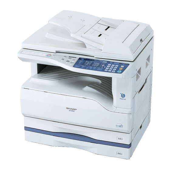
AR-M160
(With RSPF installed)
[ 1 ] GENERAL . . . . . . . . . . . . . . . . . . . . . . . . . . . . . . . . . . . . . . . . . 1 - 1
[ 2 ] SPECIFICATIONS . . . . . . . . . . . . . . . . . . . . . . . . . . . . . . . . . . . 2 - 1
[ 3 ] CONSUMABLE PARTS. . . . . . . . . . . . . . . . . . . . . . . . . . . . . . . 3 - 1
[ 4 ] EXTERNAL VIEWS AND INTERNAL STRUCTURES . . . . . . . 4 - 1
[ 5 ] UNPACKING AND INSTALLATION . . . . . . . . . . . . . . . . . . . . . . 5 - 1
[ 6 ] ADJUSTMENTS . . . . . . . . . . . . . . . . . . . . . . . . . . . . . . . . . . . . 6 - 1
[ 7 ] SIMULATIONS . . . . . . . . . . . . . . . . . . . . . . . . . . . . . . . . . . . . . 7 - 1
[ 8 ] USER PROGRAMS . . . . . . . . . . . . . . . . . . . . . . . . . . . . . . . . . 8 - 1
[ 9 ] TROUBLE CODE LIST . . . . . . . . . . . . . . . . . . . . . . . . . . . . . . . 9 - 1
[10] MAINTENANCE . . . . . . . . . . . . . . . . . . . . . . . . . . . . . . . . . . . 10 - 1
[11] DISASSEMBLY AND ASSEMBLY . . . . . . . . . . . . . . . . . . . . . . 11 - 1
[12] FLASH ROM VERSION UP PROCEDURE . . . . . . . . . . . . . . 12 - 1
[13] ELECTRICAL SECTION . . . . . . . . . . . . . . . . . . . . . . . . . . . . . 13 - 1
Parts marked with "
" are important for maintaining the safety of the set.
Be sure to replace these parts with specified ones for maintaining the safety and performance of the set.
AR-M205
CONTENTS
SHARP CORPORATION
CODE : 00ZARM205/A1E
DIGITAL COPIER
MODEL
This document has been published to be used for
after sales service only.
The contents are subject to change without notice.
AR-M160
AR-M205
Advertisement
Table of Contents

Related Manuals for Sharp AR-M160


Summary of Contents for Sharp AR-M160
- Page 1 CODE : 00ZARM205/A1E DIGITAL COPIER AR-M160 AR-M160 AR-M205 MODEL AR-M205 (With RSPF installed) CONTENTS [ 1 ] GENERAL ......... 1 - 1 [ 2 ] SPECIFICATIONS .
-
Page 3: Table Of Contents
CONTENTS [1] GENERAL [8] USER PROGRAMS 1. Note for servicing ......1-1 1. -
Page 4: General
[1] GENERAL •poorly ventilated 1. Note for servicing Pictogram The label ( ) in the fusing area of the machine indicates the following: : Caution, risk of danger : Caution, hot surface A. Warning for servicing •exposed to direct sunlight •The fusing area is hot. -
Page 5: Specifications
250 sheets paper feed unit AR-D24 (1) SPF/R-SPF 250 sheets x 2 paper feed unit AR-D25 Standard/Option Option AR-SP6 AR-M160 only SPF: AR-SP6 (AR-M160 only) RSPF AR-RP6 AR-M205 only RSPF: AR-RP6 (AR-M205 only) Original cover AR-VR5 Document load 40 sheets (Thickness 4mm or less) - Page 6 2 steps (D → D / D → S enable only when RSPF is installed) Option Paper weight 56 ~ 90 g/m² (15 ~ 21 lbs.) Not available for AR-M160 Moisture preserving None heater N. Paper exit / finishing Paper empty detection Available...
- Page 7 O. Additional functions R. External view External dimensions 590 x 577 x 520 mm(AR-M205) (W x D x H) 590 x 577 x 470 mm(AR-M160) Occupying area 590 x 531mm Auto tray switching (W x D) (When the manual tray is installed.)
-
Page 8: Consumable Parts
[3] CONSUMABLE PARTS 1.Supply system table A.USA/CANADA/Latin America Name Content Life Product name Remark Toner cartridge(Black) Toner 160K AR-202MT Life setting by A4 6% document <With IC> (Toner: Net Weight 537g) Vinyl bag Developer Developer 500K AR-202MD (Developer : Net Weight 400g) Drum kit Drum AR-202DR... -
Page 9: Environmental Conditions
2. Environmental conditions 3. Production number identification A. Transport conditions <Toner cartridge> (1) Transport conditions The label on the toner cartridge shows the date of production. Production Serial Year/ Ver.No. place number Month/ Temperature (2) Storage conditions <Drum cartridge> The lot number, printed on the front side flange, is composed of 6 digits, each digit showing the following content: Temperature B. -
Page 10: External Views And Internal Structures
[4] EXTERNAL VIEWS AND INTERNAL STRUCTURES 1. Appearance Document feeder cover (when the SPF/ Document glass Handles RSPF is installed) /document cover (when the document cover is installed) Power switch Operation panel Paper output tray Front cover Paper trays Side cover Side cover handle Bypass tray guides Bypass tray... -
Page 11: Operation Section
3. Operation Section SCAN ON LINE ORIGINAL TO COPY XY- ZOOM DUAL PAGE COPY The AR-M160 is shown below. ON LINE ZOOM PAPER SIZE DUAL 5½ PAGE COPY TRAY AUTO PRESET SCAN MENU key SCAN key/indicator ON LINE key/indicator ORIGINAL TO COPY key/indicators... -
Page 12: Motor, Solenoid, Clutch
4. Motor, solenoid, clutch Name Code Function operation Mirror motor Drives the optical mirror base (scanner unit). Shifter motor SHTM Shifts the paper exit tray. Toner motor Toner supply Duplex motor Switchback operation and paper exit motor in duplex. Cooling fan motor Cools the inside of the machine. -
Page 13: Sensor, Switch
5. Sensor, switch Name Code Function operation Mirror home position sensor MHPS Detects the mirror (scanner unit) home position. Side door switch DSWR Side door open detection Paper exit sensor (paper exit side) POD1 Detects paper exit. Shifter home position sensor SFTHP Shifter home position detection Paper exit sensor (DUP side) -
Page 14: Pwb Unit
6. PWB unit Name Function operation Copy lamp Inverter PWB Copy lamp control I / F PWB USB1.1, IEEE1284 I/F CCD sensor PWB Image scanning Main control PWB Main control PWB Tray PWB Shifter motor control IMC2 PWB Electronic sort, USB2.0 << Option:AR-EB7>> 2nd cassette PWB 2nd cassette control High voltage PWB... -
Page 15: Cross Sectional View
7. Cross sectional view Name Function/Operation Copy lamp Image radiation lamp Copy lamp unit Operates in synchronization with No. 2/3 mirror unit to radiate documents sequentially. LSU unit Converts image signals into laser beams to write on the drum. Lens unit Reads images with the lens and the CCD. -
Page 16: Unpacking And Installation
[5]UNPACKING AND INSTALLATION 2) Open the front cover. •Hold the both sides and pull down to open. 1.Installing conditions A.Copier installation Do not install your copier in areas that are: •damp, humid, or very dusty •exposed to direct sunlight •poorly ventilated •subject to extreme temperature or humidity changes, e.g., near an air conditioner or heater. -
Page 17: Removal And Storage Of Fixing Screw
B.Toner cartridge installation 4.Removal and storage of fixing screw 1) Shake the toner cartridge several times horizontally, and remove the 1) Lift the knob and gently pull out the tray. tape. Do not hold the shutter lever when shaking. After removing the tape, do not tilt or shake the toner cartridge. 4 or 5 times Shutter Tape... -
Page 18: Changing The Copy Paper Size In The Tray
5. Changing the copy paper size in the tray 4) Squeeze the lock lever of the front guide and slide the front guide to match the width of the paper, and move the left guide to the Note appropriate slot as marked on the tray. •The paper size setting cannot be changed when the machine has stopped temporarily due to running out of paper or a misfeed, or during Left guide... -
Page 19: Adjustments
[6]ADJUSTMENTS 1.Adjustment item list Section Adjustment item Adjustment procedure/SIM No. Process Developing doctor gap adjustment Developing doctor gap adjustment section MG roller main pole position adjustment MG roller main pole position adjustment Developing bias voltage check Main charger voltage check Mechanism Image position adjustment SIM-50... - Page 20 (3)Developing bias voltage check B.Mechanism section Note: Use a digital multi-meter with an internal resistance of 10MΩ or Note: If a jam error or paper empty occurs during copying in the more. adjustment by the simulation, the image data are not saved, and therefore recopying is required.
- Page 21 9) Measure the distance H between the paper lead edge and the image <Adjustment specification> print start position. Set the image print start position set value Adjustment Spec (Exposure display <<AUTO+MAIN CASSETTE LAMP>> ON) again. mode value value range •1 step of the set value corresponds to about 0.1mm shift. OC image lead PHOTO R/0.1...
- Page 22 c.Rear edge void adjustment (SIM50-1, SIM50-19) <Duplex mode adjustment> 1) Set a scale as shown in the figure below. 2nd print surface (auto duplex) off-center adjustment: SIM50-10<<TEXT+MAIN CASSETTE>> A4(8.5" x 11") <Adjustment specification> Mode Set value Specifi- cation range Paper off AUTO Add 1: Single:...
- Page 23 2) Loosen the copy lamp unit wire fixing screw. 4) Loosen the set screw of the scanner drive pulley which is not in contact with No. 2/3 mirror base unit positioning plate. 5) Without moving the scanner drive pulley shaft, manually turn the scanner drive pulley until the positioning plate is brought into contact with No.
-
Page 24: Rear Side
(3)Main scanning direction (FR direction) distortion 4) Loosen the mirror base drive pulley fixing screw on the front frame side or on the rear frame side. adjustment This adjustment must be performed in the following cases: •When the mirror base drive wire is replaced. When La <... - Page 25 1) Making of a test sheet Make test sheet by drawing parallel lines at 10mm from the both When La > Lb ends of A3 (11" x 17") white paper as shown below. (These lines Shift the mirror base B rail upward by the half of the must be correctly parallel to each other.) difference of La - Lb.
- Page 26 <Adjustment specification> Note: Since the printed copy is used as a test chart, put the scale in parallel with the edge lines. Note: A judgment must be made with 200mm width, and must not be 2) Set the test chart on the SPF and make a normal (100%) copy. made with 100mm width.
- Page 27 R side Duplex: <Adjustment specification> (SPF mode) Reduce 1: Center ±3.5mm(PHOTO lamp) 0.1mm shift Density Display Exposure Sharp Gray Set value to L side mode lamp level Chart output range Auto Auto "2" is slightly The greater the 1 ~ 99 copied.
-
Page 28: Simulations
[7] SIMULATIONS 3. List of simulations Main 1. Entering the simulation mode Contents code code Perform the following procedure to enter the simulation mode. Mirror scanning operation "#" key Interrupt key "C" key Interrupt key Mirror home position sensor (MHPS) status display Main code Start key Sub code... - Page 29 Main Main Contents Contents code code code code Jam total counter clear Image lead edge adjustment Trouble memory clear Copy lead edge position adjustment (SPF/RSPF) SPF counter clear Paper off-center adjustment Duplex print counter clear Document off-center adjustment Paper feed counter clear Memory reverse position adjustment in duplex copy Drum counter clear Rear edge void adjustment in duplex copy...
-
Page 30: Contents Of Simulations
4. Contents of simulations Main Contents Details of operation code code Mirror scanning operation When the [START] key is pressed, the home position is checked in the first place, and the mirror base performs A3 full scanning once at the set magnification ratio speed. During this scanning, the set magnification ratio is displayed. - Page 31 Main Contents Details of operation code code SPF PS release solenoid operation The SPF PS release solenoid (CLH) is turned ON for 500msec and OFF for 500msec. This operation check is repeated 20 times. After completion of the process, the machine goes to the sub code input standby mode. When the [Interrupt] key is pressed during the process, the machine goes to the sub code input standby mode.
- Page 32 Main Contents Details of operation code code Paper feed solenoid operation When this simulation is executed, the sub code is displayed on the 7-seg LED and the lamp check corresponding to the solenoid lights up. Select a solenoid with the tray select key (the lamp corresponding to the solenoid lights up) and press the [START] key, and the machine repeats operation of ON for 500ms and OFF for 500ms.
- Page 33 Main Contents Details of operation code code Duplex motor forward rotation The duplex motor is driven in forward direction (in the paper exit direction) for 30 sec. check During the process, the display section displays the sub code. After completion of the process, the machine goes into the sub code input standby mode. When the [Interrupt] key is pressed, the machine goes into the sub code input standby mode.
- Page 34 Main Contents Details of operation code code Mini maintenance preset display The mini maintenance cycle data is acquired and displayed on the 7-seg display. (Valid only when the destination is When the [Interrupt] key is pressed, the machine goes into the sub code input standby mode. set to Japan AB series) When the [CA] key is pressed, the simulation is terminated.
- Page 35 Main Contents Details of operation code code Drum counter clear When the [START] key is pressed, the drum count and the drum roasting time are reset to zero, and the drum counter value is displayed on the 7-seg LED. When the [Interrupt] key is pressed, the machine goes into the sub code input standby mode.
- Page 36 Main Contents Details of operation code code Count mode setting When any key input is made, it is displayed on the display section. When the [START] key is pressed, the set code data are acquired and stored to the count mode set variable and in the EEPROM, and the machine goes into the sub code input standby mode.
- Page 37 Main Contents Details of operation code code Cancel of stop at drum life over When this simulation is executed, the current set code number is displayed. Enter the desired code number and press the [START] key to set the code number. Code number Setting Stop at drum life over...
- Page 38 Main Contents Details of operation code code Fusing temperature setting When the simulation is terminated, the current set value is displayed. When the [%] key is pressed, (During normal copy) the setting is changed. When the [START] key is pressed, the set content is written into the EEPROM and the machine goes into the sub code input standby mode.
- Page 39 Main Contents Details of operation code code Copy density adjustment (300dpi) Used to set the copy density for each mode. (Operating procedure) When this simulation is executed, warm-up and shading are operated, and the current set value is displayed in two digits. (Default [50]) The density LED is not lighted.
- Page 40 Main Contents Details of operation code code Copy exposure level adjustment, Used to adjust the shift amount and the inclination value for each density level (1 ~ 5) when the individual setting (Text) 600dpi exposure mode is the TEXT mode (including TS) •The shift amount is the same as the gamma (gradation), and is used to set the overall brightness.
- Page 41 Main Contents Details of operation code code Image contrast adjustment Used to adjust the contrast for each mode. (300dpi) (Operating procedure) When this simulation is executed, warm-up and shading are performed, and the current set value is displayed in two digits. (Default: 50) The density LED is not lighted.
- Page 42 Main Contents Details of operation code code SPF exposure correction Used to adjust the exposure correction amount in the SPF mode (for the OC mode). (Operating procedure) When this simulation is executed, the current set value is displayed. Enter the adjustment value with the 10-key and press the [START] key. The entered set value is stored and a copy is made.
- Page 43 Main Contents Details of operation code code Main scanning/sub scanning Used to adjust the magnification ratio in the main scanning direction (front/rear) and the sub direction magnification ratio scanning direction. adjustment Enter the adjustment value with the 10-key and press the [START] key, and the entered value is saved a copy is made.
- Page 44 Main Contents Details of operation code code Image lead edge adjustment Used to adjust the copy image position and the lead edge void amount on the copy paper. This adjustment is made by adjusting the image scan start position at 100% and the print start position (resist roller ON timing).
- Page 45 Main Contents Details of operation code code Paper off-center adjustment Used to adjust the positions of copy images on copy paper and the center offset position when scanning the document. (Operating procedure) When this simulation is executed, the current set value is displayed. Enter the adjustment value with the 10-key and press the [START] key, and the entered value is stored and a copy is made.
- Page 46 Main Contents Details of operation code code Duplex copy rear edge void Used to adjust the rear edge void amount in duplex copy. adjustment (Operating procedure) When this simulation is executed, the current set value is displayed in two digits. (Adjustment range: 1 ~ 99, Center value: 50) When the set value is increased by 1, the void amount is increased by about 0.1mm.
- Page 47 Main Contents Details of operation code code Shading check The detection level of the white plate for shading is displayed. (Operating procedure) When the [START] key is pressed in the sub code input standby mode, the mirror base unit moves to the white plate for shading and the copy lamp is lighted.
-
Page 48: User Programs
[8] USER PROGRAMS The user programs allow the parameters of certain functions to be set, changed, or canceled as desired. 1. List of user programs This copier has the following user programs. Program Program name Description Default Parameters Auto clear time "Auto clear time"... - Page 49 Program Program name Description Default Parameters Layout in 2 IN 1 copy* Use this setting to select the layout pattern when two original pages 1 (Pattern 1) are copied onto a single sheet of paper. 2 (Pattern 2) 2 IN 1 copy Pattern 1 Pattern 1 Pattern 2...
-
Page 50: Setting The User Programs
Program Program name Description Default Parameters Use close paper size When this function is enabled, printing in printer mode will 0 (OFF) automatically continue using a different size of paper if the specified 1 (ON) size of paper runs out in all trays. This feature does not function in copy mode. -
Page 51: Trouble Code List
[9]TROUBLE CODE LIST 2.Details of trouble codes Main Details of trouble 1.Trouble code list code code Content IMC PWB communication trouble Main code Content Detail An abnormality occurs in communication code between the MCU PWB and the IMC PWB. IMC PWB communication trouble Cause IMC PWB-MCU PWB harness abnormality IMC PWB trouble... - Page 52 Main Details of trouble Main Details of trouble code code code code Content Interface error (Overrun) in communication with Content Shading trouble (White correction) the IMC PWB Detail The CCD white scan level is abnormal when Detail An overrun error occurs in communication the shading.
- Page 53 Main Details of trouble Main Details of trouble code code code code Content Copy lamp lighting abnormality Content Heat roller low temperature detection Detail The copy lamp does not turn on. Detail When the fusing temperature is lower than 150C° after 55sec from the start of warming Cause Copy lamp abnormality Copy lamp harness abnormality...
- Page 54 Main Details of trouble Main Details of trouble code code code code Content Main motor lock detection Content Counter check sum error (EEPROM) Detail The main motor does not rotate. Detail Check sum error of the counter area in the The motor lock signal is detected for 1sec or EEPROM more after rotation of the main motor.
-
Page 55: Maintenance
[10] MAINTENANCE 1. Maintenance table X:Check(Clean, adjust, or replace when required.) O:Clean :Replace :Adjust :Lubricate Unit name Part name When calling 100K 150K Drum peripheral OPC drum Cleaning blade Side seal F/R MC unit (MC charging electrode) (MC grid) (MC case) Transfer wire Transfer paper guide MC guide sheet (Cleaning blade attached) -
Page 56: Maintenance Display System
2. Maintenance display system C. DV seal attachment procedure Toner Life, Remaining a. Press and hold the density adjustment quantity LIGHT key for more than 5 sec, and the check *1 machine will enter the user program mode. b. Press and hold the "%" key for more than 5 sec, and the remaining quantity will be displayed on the copy quantity display in one of the following levels:... -
Page 57: Disassembly And Assembly
[11]DISASSEMBLY AND ASSEMBLY B.Charger wire Installation: The spring tip must be between two reference ribs. WARNING Before performing the disassembly procedure, be sure to •The charger wire must be free from twist or bending. remove the power cord to prevent against an electric shock. •Be sure to put the charger wire in the V groove. -
Page 58: Optical Section
2.Optical section C.Inverter PWB for copy lamp Note: When disassembling or assembling the optical unit, be careful not to touch the mirror and the reflector. Content Table glass Copy lamp unit Inverter PWB for copy lamp Copy lamp Lens unit Wire A.Table glass B.Copy lamp unit... - Page 59 E.Lens unit F.Wire Note: Do not remove screws which are not indicated in the figure. If the height of the base plate is changed, it cannot be adjusted in the market. Note: The CCD/lens unit is factory-adjusted before shipping. Since these adjustments cannot be performed in the market. Never touch the screws other than screw 2) of the CCD/lens unit.
-
Page 60: Fusing Section
3.Fusing section C.Thermistor Installation: When installing the thermistor, be sure to face the installing Contents projection (A) toward the installing surface. Fusing unit Check that the thermistor is in contact with the upper heat Thermostat roller. Thermistor Heater lamp Upper heat roller Separation pawl Lower heat roller Separation pawl... - Page 61 Floil(GU2) Grease(JFE552) F.Separation pawl Assembly: Put the fusing harness (A) on the heater lamp (B) as shown in the figure and fix them together.<R>Place the fusing harness inside the rib (C). E.Upper heat roller Disassembly: There are three pawls on the fusing cover. Remove the screws and slide the fusing cover to the right to remove.
-
Page 62: Paper Exit Section
G.Lower heat roller 4.Paper exit section Assembly: When installing the paper guide (3) before fusing, fix the Content paper guide fixing plate with screws temporarily so that the Ozone filter paper guide fixing plate (2) is in contact with the frame Cooling fan bottom under fusing (A). - Page 63 C.Paper exit unit D.Paper exit sensor / duplex sensor (A)Exit sensor (B)Duplex sensor E.Transport roller AR-M205 DISASSEMBLY AND ASSEMBLY 11-7...
-
Page 64: Mcu
F.Paper exit roller 5.MCU Assembly: Insert the spring pin so that the waveform (A) of the spring Content pin faces in the longitudinal direction of the paper exit MCU disassembly drive gear long hole (B).<R>Be sure to insert two ribs (C) A.MCU disassembly into the groove (D). -
Page 65: Lsu
7.LSU 8. Tray paper feed section/Paper transport section Content LSU unit Content Interface frame unit A.LSU unit Drive unit Solenoid (paper feed solenoid,, resist roller solenoid) Resist roller clutch / Resist roller Paper feed clutch/Paper feed roller (Semi-circular roller) A.Intermittent frame unit Assembly: Do not miss the door lock pawl. - Page 66 B.Drive unit D. Resist roller clutch/Resist roller Assembly: Move down the clutch pawl as shown below, and avoid the clutch and install. E. Paper feed clutch/Paper feed roller (Semi-circular roller) Moricote X56020 Grease G-484 C. Solenoid (paper feed solenoid, resist roller solenoid) AR-M205 DISASSEMBLY AND ASSEMBLY 11-10...
-
Page 67: Manual Multi Paper Feed Section
9.Manual multi paper feed section B. Manual multi paper feed Content Manual transport roller/Manual paper feed roller Manual multi paper feed Manual feed solenoid Manual transport clutch Pressure plate unit Manual paper feed clutch A.Manual transport roller/Manual paper feed roller Note: Push the lever at the right edge of the multi frame cover to the right upper side and remove it. - Page 68 D. Manual transport clutch F. Manual paper feed clutch Note: Push the lever at the right edge of the multi frame cover to the right upper side and remove it. E.Pressure plate unit AR-M205 DISASSEMBLY AND ASSEMBLY 11-12...
-
Page 69: Power Section
10.Power section C. High voltage P.W.B. Content Power unit Power fan High voltage P .W.B. Power P.W.B. Power switch A.Power unit D. Power P.W.B. E. Power switch B. Power fan AR-M205 DISASSEMBLY AND ASSEMBLY 11-13... -
Page 70: Developing Section
11.Developing section C.MG roller Contents Developing box Developing doctor MG roller A.Developing box B.Developing doctor Adjustment: Developing doctor gap adjustment Adjustment: MG roller main pole position adjustment Note: Attach it to fit with the attachment reference when replacing the DV blade. -
Page 71: Process Section
12.Process section 13.Others Contents Contents Drum unit Operation P.W.B. Main charger unit Tray interface P .W.B. Cleaning blade 2nd tray paper entry sensor / Paper empty sensor 2nd tray paper feed solenoid / Transport solenoid A.Drum unit 2nd tray transport clutch 2nd tray transport roller 2nd tray paper feed clutch 2nd tray paper feed roller... - Page 72 C. 2nd tray paper entry sensor / Paper empty sensor D. 2nd tray paper feed solenoid / Transport solenoid B. Tray interface P.W.B. E.2nd tray transport clutch AR-M205 DISASSEMBLY AND ASSEMBLY 11-16...
- Page 73 F. 2nd tray transport roller H. 2nd tray paper feed roller G. 2nd tray paper feed clutch I. Main motor AR-M205 DISASSEMBLY AND ASSEMBLY 11-17...
- Page 74 J. I/F P.W.B. L. Paper empty sensor M. Paper feed roller K. Paper entry sensor When removing the paper feed roller, operate the paper feed clutch with SIM 6-1, and keep the paper feed roller down as shown in the figure above for operation.
-
Page 75: Flash Rom Version Up Procedure
[12]FLASH ROM VERSION UP PROCEDURE 1.Preparation 3) PC side: Boot the maintenance program. Select the model icon. Write the download data (the file with the extension dwl) to the main body of AR-M205/M160. Necessary files for download • Maintenance.exe (Maintenance software) •... -
Page 76: Installation Procedure
7) PC side: 12) After-process: Terminate the maintenance program, and turn on the Double click "Special (MCU/MCU2/FAX)" in the main tree item to power of the main body. develop the sub tree items, and double click "DWL Download" in the sub tree items. - Page 77 3) Check that the following display is shown. 6) Check that the path to the folder which includes the maintenance tool Select "Install from a list or the specific location" and press the NEXT driver (Pegasus.inf) is shown, and press the NEXT button. button.
- Page 78 3) Check that the new hardware search wizard is shown. Press the 7) Specify the folder which includes the maintenance tool driver NEXT button. (Pegasus.inf), and press the OPEN button. Check that the path to the folder which includes the maintenance tool driver (Pegasus.inf) is properly displayed, and press the OK button.
-
Page 79: Electrical Section
[13] ELECTRICAL SECTION 1.Block diagram High-speed USB2.0 MM_BI0/BI1/PH_B MM_AI0/AI1/PH_A TM+,TM- /MMRDY /MMRDY /MMD AR-M205 ELECTRICAL SECTION 13-1... -
Page 80: Circuit Descriptions
2.Circuit descriptions c. IEEE1284 circuit The IEEE1284 driver is used to perform interface between the ASIC A. Main PWB (MCU) (engine) and the host. (1) Operation circuit IEEE1284 a. General Centronics driver The operation circuit is composed of the key matrix circuit and the dis- connector ASIC IC403... - Page 81 (1) Noise filter circuit (3) Inverter and control circuit (Flyback converter system) The filter circuit is composed of L and C. It reduces common noises and normal mode noises generated from the AC line. The common noise means that generated in each line for GND. Its noise component is delivered through C001, C003, and C007 to GND.
- Page 82 The control circuit is subject to negative feedback from the secondary side as shown in fig (4). A photo coupler (PC002) is employed to insulate between the primary side and the secondary side to feed back the control signal to the primary side. When the output voltage is increased by energy transmission from T001, the voltage detected by R109 and R111 is compared with the reference voltage of IC102.
-
Page 83: Actual Wiring Diagram
3.Actual wiring diagram ACTUAL WIRING DIAGRAM 1/7 35FE-BT-VK-N (WHITE) B7B-PH-K-S (RED) B18B-PHDSS-B (WHITE) 22FE-BT-VK-N (WHITE) 22FE-BT-VK-N (WHITE) Option AUDITOR B3B-PH-K-SX 24FMN-BTRK-A (WHITE) B3B-PH-K-BK (BLACK) (BLACK) B5B-PH-K-S B3B-PH-K-S B6B-PH-K-S (WHITE) (WHITE) 1-171825-2 (WHITE) 13FE-BT-VK-N (WHITE) 13FE-BT-VK-N IMSA-9610S- (WHITE) (BLACK) AR-M205 ELECTRICAL SECTION 13-5... - Page 84 ACTUAL WIRING DIAGRAM 2/7 AR-M205 ELECTRICAL SECTION 13-6...
- Page 85 ACTUAL WIRING DIAGRAM 3/7 SPF INTERFACE AR-M205 ELECTRICAL SECTION 13-7...
- Page 86 ACTUAL WIRING DIAGRAM 4/7 AR-M205 ELECTRICAL SECTION 13-8...
- Page 87 ACTUAL WIRING DIAGRAM 5/7 AR-M205 ELECTRICAL SECTION 13-9...
- Page 88 ACTUAL WIRING DIAGRAM 6/7 NEUTRAL LIVE AR-M205 ELECTRICAL SECTION 13-10...
- Page 89 ACTUAL WIRING DIAGRAM 7/7 AR-M205 ELECTRICAL SECTION 13-11...
- Page 90 LEAD-FREE SOLDER The PWB’s of this model employs lead-free solder. The “LF” marks indicated on the PWB’s and the Service Manual mean “Lead-Free” solder. The alphabet following the LF mark shows the kind of lead-free solder. Example: <Solder composition code of lead-free solder> Solder composition Solder composition code Solder composition...
-
Page 91: Circuit Diagram
AR-200M Japan only AR-160M Japan only AR-M205 Except Japan AR-M160 Except Japan AR-5220 MODEL Except Japan CONTENTS 1. MAIN PWB ......... . . 1 . - Page 92 0.1u 0.1u 0.1u 0.1u 0.1u 100p C287 100p C286 100p C285 100p 100p 100p N.M. N.M. 100p N.M. P64/IRQ0 P60/DREQ0/CS4 P65/IRQ1 P61/TEND0/CS5 P66/CS6/IRQ2 P62/DREQ1 P67/CS7/IRQ3 P63/TEND1 PA7/A23/IRQ7 P27/PO7/TIOCB5 PA6/A22/IRQ6 P26/PO6/TIOCA5 PA5/A21/IRQ5 P25/PO5/TIOCB4 PA4/A20/IRQ4 P24/PO4/TIOCA4 P23/PO3/TIOCD3 PA3/A19 P22/PO2/TIOCC3 PA2/A18 P21/PO1/YICOB3 PA1/A17 P20/PO0/TIOCA3 PA0/A16 WDTOVF...
- Page 93 0.1u 0.1u 0.1u 0.1u 0.1u 0.1u 0.1u 0.1u 0.1u 0.1u 0.1u UDZS3.9B 0.1u 0.1u 0.1u 2200p C270 0.1u UDZS3.9B 0.1u 0.1u 0.1u 2200p C269 0.1u UDZS3.9B 1608size) 1000p( C268 470p C310 UDZS3.9B 470p C309 470p C308 C267 1608size) 1000p( 470p C307 470p C306...
- Page 94 AR-M205/M160/l5220 – 3 –...
- Page 95 100p C118 100p C117 N.M. C110 100p C116 100p C109 100p C115 100p C108 100p C114 100p C107 100p C113 100p 100p C106 100p C112 100p 100p C105 0.1u C111 0.1u C262 100p 100p C104 0.1u 0.1u C103 10kJ R204 10kJ R203 10kJ...
- Page 96 KDS121 DAN202U KDS121 DAN202U KDS120 DAP202U AR-M205/M160/l5220 – 5 –...
- Page 97 AR-M205/M160/l5220 – 6 –...
- Page 98 AR-M205/M160/l5220 – 7 –...
- Page 99 470J R186 470J R205 5VEN 10kJ R180 KDS120 DAP202U N.M. C254 KDS121 DAN202U N.M. C253 N.M. C239 N.M. C238 N.M. C237 N.M. C236 N.M. C235 N.M. C273 N.M. C274 N.M. C275 N.M. C276 N.M. C277 N.M. C278 N.M. C279 N.M. C280 KDS121 DAN202U...
- Page 100 470J R189 470J R209 470J R188 470J R208 20kJ R200 470J R191 470J R207 470J R190 470J R206 KDS121 DAN202U KDS120 DAP202U 10kJ R197 N.M. R196 R195 N.M. R194 KDS121 DAN202U KDS120 DAP202U KDS121 DAN202U KDS120 DAP202U 20kJ R193 470J R192 470J R210...
- Page 101 AR-M205/M160/l5220 – 10 –...
- Page 102 AR-M205/M160/l5220 – 11 –...
- Page 103 AR-M205/M160/l5220 – 12 –...
- Page 104 AR-M205/M160/l5220 – 13 –...
- Page 105 N.M. N.M. N.M. N.M. N.M. N.M. N.M. AR-M205/M160/l5220 – 14 –...
- Page 106 /Q14 DATA1 /Q15 /Q13 DATA2 /Q12 DATA3 /Q11 DATA4 /Q10 DATA5 /Q16 GND5 /Q32 GND4 /Q31 GND3 /Q30 GND2 /Q29 GND1 /Q28 /Q27 CLOCK /Q19 /Q21 /LATCH /Q23 /Q22 /STROBE /Q18 /Q20 /Q17 /Q26 /Q24 /Q25 Dig3 Dig2 Dig1 AR-M205/M160/l5220 –...
- Page 107 Shield AR-M205/M160/l5220 – 16 –...
- Page 108 AR-M205/M160/l5220 – 17 –...
- Page 109 AR-M205/M160/l5220 – 18 –...
- Page 112 COPYRIGHT 2003 BY SHARP CORPORATION All rights reserved. All rights reserved. All rights reserved. Printed in Japan. Printed in Japan. Printed in Japan. No part of this publication may be reproduced, No part of this publication may be reproduced, No part of this publication may be reproduced,...