AMX Modero ViewPoint MVP-5200i Operation/Reference Manual
Modero viewpoint touch panel with intercom, 5.2" and 5”
Hide thumbs
Also See for Modero ViewPoint MVP-5200i:
- Operation/reference manual (202 pages) ,
- Installation manual (36 pages) ,
- Datasheet (2 pages)

Related Manuals for AMX Modero ViewPoint MVP-5200i


Summary of Contents for AMX Modero ViewPoint MVP-5200i
- Page 1 Operation/Reference Guide MVP-5200i ® ® Modero ViewPoint Touch Panel with Intercom, 5.2" and 5” Touch Panels L a s t R e v i s e d : 8 / 1 7 / 2 0 1 2...
- Page 2 AMX is not responsible for products returned without a valid RMA number. AMX is not liable for any damages caused by its products or for the failure of its products to perform. This includes any lost profits, lost savings, incidental damages, or consequential damages.
- Page 3 LICENSE GRANT. AMX grants to Licensee the non-exclusive right to use the AMX Software in the manner described in this License. The AMX Software is licensed, not sold. This license does not grant Licensee the right to create derivative works of the AMX Software.
- Page 4 FCC Information This device complies with Part 15 of the FCC Rules. Operation is subject to the following two conditions: (1) this device may not cause harmful interference, and (2) this device must accept any interference received; including interference that may cause undesired operation. Federal Communications Commission (FCC) Statement This equipment has been tested and found to comply with the limits for a Class B digital device, pursuant to Part 15 of...
-
Page 5: Table Of Contents
Modero Setup and System Settings ............... 20 Accessing the Setup and Protected Setup Pages............20 Setting the Panel’s Device Number ................21 Wireless Settings - Wireless Access Overview ............21 MVP-5200i Modero® ViewPoint® Touch Panel with Intercom, 5.2 and 5”... - Page 6 Security Settings ......................55 Protected Setup Navigation Buttons ..............57 System Settings Page....................57 Wireless Settings Page ....................59 Security Modes ....................... 61 Open ..........................62 WEP..........................62 WPA-PSK Settings ......................64 MVP-5200i Modero® ViewPoint® Touch Panel with Intercom, 5.2 and 5”...
- Page 7 Gesture VNC/Mouse Support ..................99 Gesture Custom Event ....................99 Enabling or Disabling the Gesture Custom Event ............99 ^GCE............................99 Page Commands ....................100 @APG ............................100 @CPG ............................100 MVP-5200i Modero® ViewPoint® Touch Panel with Intercom, 5.2 and 5”...
- Page 8 ^BMF ............................114 ^BMI ............................116 ^BML ............................116 ^BMP ............................116 ^BNC ............................117 ^BNN............................117 ^BNT............................117 ^BOP ............................117 ^BOR ............................118 ^BOS ............................118 ^BPP ............................118 MVP-5200i Modero® ViewPoint® Touch Panel with Intercom, 5.2 and 5”...
- Page 9 MVP Panel Lock Passcode Commands ................ 127 ^LPC............................127 ^LPR ............................127 ^LPS ............................127 Text Effects Names....................128 Button Query Commands ..................128 ?BCB............................129 ?BCF ............................130 ?BCT ............................130 ?BMP ............................131 MVP-5200i Modero® ViewPoint® Touch Panel with Intercom, 5.2 and 5”...
- Page 10 ^VKS ............................141 Embedded codes ....................142 Panel Setup Commands ..................143 @PWD ............................. 143 ^PWD ............................. 143 Dynamic Image Commands................... 144 ^BBR ............................144 ^RAF ............................144 ^RFR ............................144 MVP-5200i Modero® ViewPoint® Touch Panel with Intercom, 5.2 and 5”...
- Page 11 ^PHN-AUTOANSWER ......................150 ^PHN-MSGWAITING ....................... 150 ^PHN-PRIVACY ........................150 ^PHN-REDIAL.......................... 150 ^PHN-TRANSFERRED ......................150 ?PHN-AUTOANSWER......................151 ^PHN-CALL ..........................151 ^PHN-DTMF ..........................151 ^PHN-HANGUP........................151 ^PHN-HOLD ..........................151 ?PHN-LINESTATE ........................151 MVP-5200i Modero® ViewPoint® Touch Panel with Intercom, 5.2 and 5”...
- Page 12 Special Escape Sequences ................... 164 Complex Script Support ..................166 Appendix B: Wireless Technology ..............169 Overview of Wireless Technology................. 169 Terminology......................170 802.1x ......................... 170 AES..........................170 CERTIFICATES (CA) ..................... 170 MVP-5200i Modero® ViewPoint® Touch Panel with Intercom, 5.2 and 5”...
- Page 13 Panel Doesn’t Respond To Touches ................177 Battery Will Not Hold Or Take A Charge ..............177 MVP-5200i Isn’t Appearing In The Online Tree Tab ............ 178 MVP Can’t Obtain a DHCP Address ................178 My WEP Doesn’t Seem To Be Working ............... 178 NetLinx Studio Only Detects One Of My Connected Masters ........
- Page 14 Table of Contents MVP-5200i Modero® ViewPoint® Touch Panel with Intercom, 5.2 and 5”...
-
Page 15: Introduction
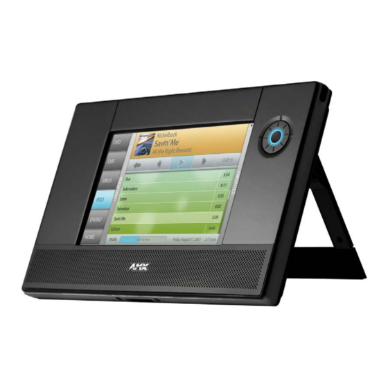
Introduction Overview The MVP-5200i is a wireless-only ergonomic device capable of VoIP intercom telephone communications, quick wakeup and connection time, extended battery life for longer operation between charges and includes a 5.2" Color Active LCD to display a 800 x 480 pixel image with 262,144 colors. Models includes a 5.2" Color Active LCD to display a 800 x 480 pixel image with 262,144 colors, available in black (FG5966-01) and white (FG5966-02), or a 5.0"... - Page 16 Introduction The MVP-5200i comes with an integrated rear "kickstand", allowing it to be used and displayed away from a Charging Station if necessary (FIG. 2). It also comes with a pre-installed 802.11g WPA/WPA2 SDIO wireless card. Kickstand DC power jack Mini-USB port FIG.
- Page 17 • Horizontal: + 60° (left from center) and - 60° (right from center) FG5966-03 & FG5966-04: • Vertical: + 50° (up from center) and - 70° (down from center) • Horizontal: + 70° (left from center) and - 70° (right from center) MVP-5200i Modero® ViewPoint® Touch Panel with Intercom, 5.2 and 5”...
- Page 18 Transmit IR over 20 feet (6.10 m) from the panel. • IR emitters on G4 panels share the device address number of the panel. • Transmits AMX fixed frequencies at 38KHz and 455KHz and user programmable frequencies from 20KHz to 1.5MHz Operating/Storage •...
-
Page 19: Memory
Basic Operation The MVP-5200i is operated using both its integral touchscreen and the navigation wheel on the right side of the device. If the device has gone into its Standby Mode, a touch of the touchscreen or of the button wheel will reactivate it. -
Page 20: Navigation Wheel
Calibration page (page 75). If the MVP-5200i needs to be shut down or reset for any reason, press and hold down the wheel center button until the popup stating “panel shutting down” appears or the screen goes dark. Continuously holding down the... -
Page 21: Navigation Wheel Behavior In Each Power Mode
Shut Down (Off) Charging Same as Sleep Mode The navigation wheel may also be programmed to initiate specific commands. For more information, please see the Programming section on page 95. MVP-5200i Modero® ViewPoint® Touch Panel with Intercom, 5.2 and 5”... -
Page 22: Turning On The Mvp-5200I
Kick Stand Since the MVP-5200i device is designed to be a unit used away from its charging station, it has an extendable "kickstand" on the back of the unit (FIG. 2). This may be opened by physically lifting the free end of the kick stand away from the device. -
Page 23: Accessories
• MVP-WCS-52: Wall Charging Station (FG5966-1X) Powering the MVP-TCS-52 The MVP-TCS-52 uses a PS3.0 power supply (included with the MVP-5200i touch panel or available separately from www.amx.com) to provide direct power for the MVP panel both for standard functions and for charging its internal battery. -
Page 24: Connections And Wiring
Charging Station. The charger pins in the bottom of the cradle (FIG. 7) must be in contact with the connector on the bottom of the MVP-5200i for it to start recharging. The MVP panel will stop recharging automatically once the battery has achieved its maximum charge. -
Page 25: Wall Charging Station
FIG. 8 MVP-WCS-52-GB Wall Charging Station - Front The features of the MVP-WCS-52 include: Full charging of a docked MVP-5200i in approximately 4.5 hours Touch panel code lock for security Integrated docking alignment guides for easy docking ... -
Page 26: Unlocking The Touch Panel
Wall Charging Station: Press the Security Release button (see FIG. 9). A password keypad will pop up on the MVP-5200i screen. Enter a password in the password keypad and press Enter. Wait for the Wall Charging Station to pivot the touch panel away from the wall. -
Page 27: Recharging
Slide the device into the Wall Charging Station cradle bottom-first and make sure the device is fully seated in the Charging Station. Press the top of the MVP-5200i back until it clicks. The touch panel is now locked into the Charging Station, and the station will automatically charge the device’s battery. (Please refer to the Power Management Page section on page 50 to check on the battery charge status.) - Page 28 The maximum recommended torque to screw in the wings on the plastic back box is 105 IN-OZ [74 N-CM]. Applying excessive torque while tightening the wing screws, such as with powered screwdrivers, can strip out the wings or damage the plastic back box. MVP-5200i Modero® ViewPoint® Touch Panel with Intercom, 5.2 and 5”...
- Page 29 Insert the two installation screws from the MVP-WCS-52 Installation Kit into the screw holes in the interior compartment of the device and tighten them to anchor the device to the box (FIG. 13). MVP-5200i Modero® ViewPoint® Touch Panel with Intercom, 5.2 and 5”...
- Page 30 Wall Charging Station. The neodymium magnets will hold it in place. To remove the MVP-5200i, unlock the touch panel (see the Unlocking the Touch Panel section on page 12 for more information) and wait for the touch panel to pull away from the Wall Charging Station. Once it has been released, grip it by the top of the device, and pull it free from the Charging Station.
-
Page 31: Installing The Optional Metal Rough-In Box
MVP-5200i Modero® ViewPoint® Touch Panel with Intercom, 5.2 and 5”... -
Page 32: Other Mvp-Wcs-52 Installations
To avoid this, the box may be installed with adhesive. Test an unobtrusive spot on the back of the box with a sample of the adhesive to check for any adverse reactions before installing the device. MVP-5200i Modero® ViewPoint® Touch Panel with Intercom, 5.2 and 5”... -
Page 33: Configuring Communication
Studio and TPDesign4 programs. In the example below (FIG. 15), three MVP-5200i devices are shown at varying distances from the two AP gateways. As with any other AP network, the gateways are spaced so as to allow a maximum wireless coverage for the three devices. -
Page 34: Ir Communication
Configuring Communication IR Communication In certain situations, the MVP-5200i may be used as an infrared remote device for other AMX controllers. The device can transmit IR over 20 feet (6.10 m) from the panel at frequencies of 38KHz, 455KHz, and 1.2MHz. -
Page 35: Setting The Panel's Device Number
Wireless Settings page will not work until the panel is rebooted. MVP touch panels connect to a wireless network through their use of the pre-installed AMX 802.11g wireless interface card. This allows users to communicate with an Access Point (AP). The AP communication parameters must match those of the pre-installed wireless interface card installed within the panel. -
Page 36: Configuring Wireless Network Access
Configuring Communication Configuring Wireless Network Access The first step in connecting the MVP-5200i to a wireless network is to configure the wireless communication parameters within the device’s Wireless Settings page. This page only configures the card to communicate to a target AP: the device must still be directed to communicate with the correct Master. -
Page 37: Wireless Communication Using A Static Ip Address
Security (if detectable - such as WEP, OPEN and UNKNOWN) - security protocol enabled on the displaying the individual APs’ signal level. Signal - MAC Address - Unique identification of the transmitting Access Point FIG. 20 Site Survey page MVP-5200i Modero® ViewPoint® Touch Panel with Intercom, 5.2 and 5”... - Page 38 If more are detected, then they will be enabled as appropriate so that the user can scroll through the list. Access points using channel 8 should never be used, as the MVP-5200i may receive too much interference from other devices in the area.
-
Page 39: Step 2: Configure The Card's Wireless Security Settings
The Wireless Site Survey page will note the available security of each AP. If your AP is not configured for Open security, you will not be able to connect in this security mode. MVP-5200i Modero® ViewPoint® Touch Panel with Intercom, 5.2 and 5”... - Page 40 The Signal Level bar should provide some information regarding the strength of the connection to a Access Point. If no signal is displayed, configuration of the network could be required. MVP-5200i Modero® ViewPoint® Touch Panel with Intercom, 5.2 and 5”...
-
Page 41: Automatically Setting Ssid
Abc. The alpha-numeric string is AMX by default, but can later be changed to any 32-character entry. This string must be duplicated within the Network Name (SSID) field on the AP. As an example, if the SSID is TECHPUBS, this word and the case within must match both the Network Name MVP-5200i Modero®... -
Page 42: Configuring Multiple Wireless Touch Panels To Communicate To A Target Ap
As an example, all panels should be set to Default Key #1 and be using aa:bb:cc.as the Current Key string value. This same Key value and Current Key string should be used on the target AP. Repeat steps 1 - 3 on each panel. MVP-5200i Modero® ViewPoint® Touch Panel with Intercom, 5.2 and 5”... -
Page 43: Ethernet Over Usb
Under IP address, provide an IP address. Ensure that it is in the same subnet as the IP address given to the usb0 interface on the MVP-5200i, but make sure that it has a different node number. The IP address cannot be the same as the panel`s USB IP address. - Page 44 FIG. 29 Found New Hardware Wizard while searching for the driver Once the system finds the driver, it displays its choice (FIG. 30). Click Finish to complete the driver installation. MVP-5200i Modero® ViewPoint® Touch Panel with Intercom, 5.2 and 5”...
- Page 45 IP address to the corresponding interface on the Windows side. Usually, this IP address is a random value and in a totally different subnet. The user may set the Windows network properties for the Ethernet over USB interface to have a specific address whenever the Windows XP system detects an MVP-5200i with an assigned IP address.
-
Page 46: Configure A Virtual Netlinx Master Using Netlinx Studio
Click the Communications Settings button to open the Communications Settings dialog (FIG. 33). FIG. 33 Communications Settings dialog Click the NetLinx Master radio button in the Platform Selection section. Click the Virtual NetLinx Master radio button in the Transport Connection Option section. MVP-5200i Modero® ViewPoint® Touch Panel with Intercom, 5.2 and 5”... -
Page 47: Wireless
Set the Username and select Done. Select the blank field Password to open the keyboard. Set the Password and select Done. Press the Back button to return to the Protected Setup page. MVP-5200i Modero® ViewPoint® Touch Panel with Intercom, 5.2 and 5”... -
Page 48: Master Connection To A Virtual Master
PC to communicate with a panel. Everything else, such as the Authentication, is greyed out because the procedure is not being made through the Master’s UI. MVP-5200i Modero® ViewPoint® Touch Panel with Intercom, 5.2 and 5”... - Page 49 Master, virtual or not. A Virtual Master system value can be set within the active AMX software applications such as NetLinx Studio, TPD4, or IREdit. Press the Master IP/URL field to open a Keyboard and enter the IP Address of the PC used as the Virtual Master.
-
Page 50: Using G4 Web Control To Interact With A G4 Panel
Refer to the G4 Web Control Settings Page section on page 76 for more detailed field information. Verify your NetLinx Master (ME260/64 or NI-Series) has been installed with the latest firmware KIT file from www.amx.com. Refer to the NetLinx Master instruction manual for more detailed information on the use of the new Web-based NetLinx Security. - Page 51 Press the on-screen Reboot button to save any changes and restart the device. Verify that the NetLinx Master’s IP Address and System Number have been properly entered into the Master Connection section of the System Settings page. MVP-5200i Modero® ViewPoint® Touch Panel with Intercom, 5.2 and 5”...
-
Page 52: Using The Netlinx Master To Control The G4 Panel
If the Master has been previously configured for secured communication, click OK to accept the AMX SSL certificate, if SSL is enabled, and then enter a valid username and password into the fields within the Login dialog. Click OK to enter the information and proceed to the Master’s Manage WebControl Connections window. - Page 53 Enter the Web Control session password into the Session Password field (FIG. 44). This password was previously entered into the Web Control Password field within the G4 Web Control page on the panel. MVP-5200i Modero® ViewPoint® Touch Panel with Intercom, 5.2 and 5”...
- Page 54 A small circle appears within the on-screen G4 panel page and corresponds to the location of the mouse cursor. A left-mouse click on the computer-displayed panel page equates to an actual touch on the target G4 panel page. MVP-5200i Modero® ViewPoint® Touch Panel with Intercom, 5.2 and 5”...
-
Page 55: Setup Pages
Setup Pages Overview The MVP-5200i features on-board Setup pages. Use the options in the Setup pages to access panel information and make various configuration changes. To access the Setup pages, press the center button of the navigation wheel and hold for 3 to 5 seconds (FIG. -
Page 56: Navigation Buttons
Press to access the Audio Settings page in order to adjust audio parameters on the panel. Press to access the Power Management page in order to monitor battery status in the panel. FIG. 47 Setup Page Navigation Buttons MVP-5200i Modero® ViewPoint® Touch Panel with Intercom, 5.2 and 5”... -
Page 57: Protected Setup Pages
The Information button allows access of both the Project Information page, which contains data on the TPDesign4 file being used with the MVP-5200i, and the Panel Information page, which contains detailed information on the panel itself. To access these pages: Press and hold the Information button until the Project Information button and the Panel Information button slide from the left. - Page 58 Receivers tab). • For example, if you set the AMX IR 38K Port to 7 and then put a button on the panel with a channel code of 5 and a port of 7 , it will trigger the IR code in slot 5 of the AMX IR 38K Port.
-
Page 59: Panel Information Page
Bulb Hours: Displays the number of hours elapsed with the display on full power. Screen Width: Displays the screen width (in pixels). MVP-5200i = 640 pixels. Screen Height: Displays the screen height (in pixels). MVP-5200i = 480 pixels. Screen Refresh Rate: Displays the video refresh rate applied to the incoming video signal. - Page 60 Displays the shutdown string used during a panel’s Shutdown mode. File System: Displays the amount of Compact Flash memory available on the panel. RAM: Displays the available RAM (or Extended Memory module) on the panel. MVP-5200i Modero® ViewPoint® Touch Panel with Intercom, 5.2 and 5”...
-
Page 61: Time & Date Settings Page
FIG. 50 Time and Date Settings page The MVP-5200i does not have an on-board clock, so the only way to modify a panel’s time without altering the Master is via NetLinx Code. Features on this page include: Time &... -
Page 62: Audio Settings Page
Press the bargraph to the left or right of the graph marker to adjust the volume level in one-percent increments (range 0 - 100), or press the bargraph and hold to move the graph marker to the desired level. MVP-5200i Modero® ViewPoint® Touch Panel with Intercom, 5.2 and 5”... -
Page 63: Wav Files - Supported Sample Rates
• The Mute button mutes the Line-In volume. WAV files - Supported Sample Rates The following sample rates for WAV files are supported by MVP-5200i panels: Supported WAV Sample Rates • 48000 Hz •... -
Page 64: Power Management Page
A value of Off disables this feature. Range = 15, 30 minutes; 1, 2, 3, 4 hours Default = Off MVP-5200i Modero® ViewPoint® Touch Panel with Intercom, 5.2 and 5”... - Page 65 • Disabled - Clicking on this button activates the brightness limit set on the panel, conserving battery power. Activating this feature causes the panel to function at 80% of full brightness and overrides the Panel Brightness value set on the Setup page. MVP-5200i Modero® ViewPoint® Touch Panel with Intercom, 5.2 and 5”...
- Page 66 Setup Pages MVP-5200i Modero® ViewPoint® Touch Panel with Intercom, 5.2 and 5”...
-
Page 67: Protected Setup Pages
Opens a keypad used to view or change the device name of the panel. Synchronize Panel Opens a confirmation dialog popup window that asks to synchronize the IP Names: Hostname and G4 Web Control Name values to the Device Name. MVP-5200i Modero® ViewPoint® Touch Panel with Intercom, 5.2 and 5”... - Page 68 • Remove User Pages - Removes all TPD4 touch panel pages currently on the panel, including the pre-installed AMX Demo pages. This option invokes a Confirmation dialog, prompting you to confirm your selection before removing the panel pages.
-
Page 69: Security Settings
• Login failure attempt pauses 4 seconds before another login attempt is allowed. • After 3 consecutive unsuccessful SSH login attempts, login lockout is enabled for 15 minutes. • Login and logout audit logging is enabled. • DoD login banner is enabled. MVP-5200i Modero® ViewPoint® Touch Panel with Intercom, 5.2 and 5”... - Page 70 For more information on configuring AMX devices for a secure environment, please refer to the guide Security Profiles: Configuring AMX Devices For Installation Into a Secure Environment, available at www.amx.com.
-
Page 71: Protected Setup Navigation Buttons
The icon in the upper-right corner of each Protected Setup page provides a constant visual indication of current connection status. Note: a Lock appears on the icon if the panel is connected to a secured NetLinx Master. MVP-5200i Modero® ViewPoint® Touch Panel with Intercom, 5.2 and 5”... - Page 72 IP Address and Subnet Mask keypads. Refer to the Ethernet Over USB section on page 29 for more detailed information on using the System Settings page. MVP-5200i Modero® ViewPoint® Touch Panel with Intercom, 5.2 and 5”...
-
Page 73: Wireless Settings Page
This unique address identifies the wireless Ethernet card in the panel (read- only). Active Roaming on When enabled, connection allows active roaming between APs by switching Channels 1,6,11 between channels 1, 6, and 11 if the other channel is unavailable. MVP-5200i Modero® ViewPoint® Touch Panel with Intercom, 5.2 and 5”... - Page 74 • AP SIte Survey Refer to the Configuring Wireless Network Access section on page 22 for more information on configuring the panel for wireless network access using the various security options. MVP-5200i Modero® ViewPoint® Touch Panel with Intercom, 5.2 and 5”...
-
Page 75: Security Modes
(FIG. 60) offers EAP-LEAP (page 66), EAP-FAST (page 68), EAP-PEAP (page 69), EAP-TTLS (page 71), and EAP-TLS (page 72). FIG. 59 Wireless Security: Simple Mode FIG. 60 Wireless Security: Enterprise Mode MVP-5200i Modero® ViewPoint® Touch Panel with Intercom, 5.2 and 5”... -
Page 76: Open
26 characters in length. The length of the key entered determines the level of WEP encryption employed (64 or 128-bit). 128-bit keys may be used if supported by the internal wireless card. MVP-5200i Modero® ViewPoint® Touch Panel with Intercom, 5.2 and 5”... - Page 77 Refer to the Configuring Wireless Network Access section on page 22 and the Using the Site Survey Tool section on page 23 for further details on these security options. MVP-5200i Modero® ViewPoint® Touch Panel with Intercom, 5.2 and 5”...
-
Page 78: Wpa-Psk Settings
Refer to the Configuring Wireless Network Access section on page 22 for details on these security options. Refer to the Using the Site Survey Tool section on page 23 for more information on using this tool. MVP-5200i Modero® ViewPoint® Touch Panel with Intercom, 5.2 and 5”... -
Page 79: Eap Security & Server Certificates - Overview
If no server certificate will be used, this field should be left blank. If the field contains a file name, then a valid certificate file with the same file name must be previously installed on the panel. Otherwise the authentication process will fail. MVP-5200i Modero® ViewPoint® Touch Panel with Intercom, 5.2 and 5”... -
Page 80: Eap-Leap
This works in tandem with the Password string which is similar to the password entered to gain access to a secured workstation. Typically, this is in the form of a username such as jdoe@amx.com. Password: Opens an on-screen keyboard. Enter the network password string specified... - Page 81 Protected Setup Pages FIG. 62 EAP-LEAP sample Cisco System Security page MVP-5200i Modero® ViewPoint® Touch Panel with Intercom, 5.2 and 5”...
-
Page 82: Eap-Fast
This works in tandem with the Password string which is similar to the password entered to gain access to a secured workstation. Typically, this is in the form of a username such as: jdoe@amx.com. Anonymous Identity: Opens an on-screen keyboard to enter an IT provided alphanumeric string which (similar to the username) is used as the identity, but that does not represent a real user. -
Page 83: Eap-Peap
This works in tandem with the Password string, which is similar to the password entered to gain access to a secured workstation. Typically, this is in the form of a username such as jdoe@amx.com. Password: Opens an on-screen keyboard to enter the network password string specified... - Page 84 • Save - store the new security information, apply changes, and return to the previous page. Refer to the EAP Authentication section on page 184 and the Using the Site Survey Tool section on page 23 for further details on these security options. MVP-5200i Modero® ViewPoint® Touch Panel with Intercom, 5.2 and 5”...
-
Page 85: Eap-Ttls
This works in tandem with the Password string which is similar to the password entered to gain access to a secured workstation. Typically, this is in the form of a username such as: jdoe@amx.com. Anonymous Identity: Opens an on-screen keyboard. Enter an IT provided alpha-numeric string which (similar to the username) used as the identity, but that does not represent a real user. -
Page 86: Eap-Tls
This works in tandem with the Password string, which is similar to the password entered to gain access to a secured workstation. Typically, this is in the form of a username such as: jdoe@amx.com. Certificate Authority: When pressed, the panel displays an on-screen Certificate Authority (CA) File Location keyboard, for entering the name of the certificate authority file which is used to validate the server certificate. -
Page 87: Client Certificate Configuration
PEM (Privacy Enhanced Mail) DER (Distinguished Encoding Rules) PKCS12 (Public Key Cryptography Standard #12) PKCS12 files are frequently generated by Microsoft certificate applications. Otherwise, PEM is more common. MVP-5200i Modero® ViewPoint® Touch Panel with Intercom, 5.2 and 5”... - Page 88 Certificate Types Supported by the Modero Firmware Configuration Field Name Certificate File Type Supported Certificate Authority field PEM and DER Client Certificate field PEM and DER Private Key field .PEM, DER, and PKCS12 MVP-5200i Modero® ViewPoint® Touch Panel with Intercom, 5.2 and 5”...
-
Page 89: Calibrate Page
Press and hold the center button on the navigation wheel for 6 seconds to access the Calibrate page (see FIG. 53). Press the crosshairs in turn. If the crosshairs are not touched within ten seconds, the MVP-5200i will return to the Protected Setup page. -
Page 90: G4 Web Control Settings Page
Displays the maximum number of users that can be simultaneously connected Connections: to this panel via VNC. Default = 1. Current Connection Displays the number of users currently connected to this panel via VNC. Count: MVP-5200i Modero® ViewPoint® Touch Panel with Intercom, 5.2 and 5”... - Page 91 Refer to the Using G4 Web Control to Interact with a G4 Panel section on page 36 for instructions on using the G4 Web Control page with the web-based NetLinx Security application. MVP-5200i Modero® ViewPoint® Touch Panel with Intercom, 5.2 and 5”...
-
Page 92: Other Settings
Clears all files previously stored in the flash memory cache. Image Cache Status RAM Max Size: The maximum size allocated to the RAM cache. RAM Current Size: The size of the current RAM cache contents. MVP-5200i Modero® ViewPoint® Touch Panel with Intercom, 5.2 and 5”... -
Page 93: Password Settings Page
Use the UP/DN buttons to scroll through the list of saved User Access user names and passwords. MVP-5200i Modero® ViewPoint® Touch Panel with Intercom, 5.2 and 5”... - Page 94 Enter the new password into the Password keyboard and press Done. To view all previous instances of users accessing the device: From the Password Settings page, press the Enable button to highlight it. The MVP-5200i will record all successful and unsuccessful attempts to access the touch panel.
-
Page 95: Sip Settings Page
Port Number: The option displays the port you use to connect to the proxy server. The stan- dard SIP port is 5060, but some providers use different ports. MVP-5200i Modero® ViewPoint® Touch Panel with Intercom, 5.2 and 5”... - Page 96 This field is optional. Save/Cancel: • Save - store the new security information, apply changes, and return to the previous page. • Cancel - discard changes and return to the previous page. MVP-5200i Modero® ViewPoint® Touch Panel with Intercom, 5.2 and 5”...
-
Page 97: Tools
Protected Setup Pages Tools Press and hold the Tools button to access the MVP-5200i’s Panel Logs, Panel Statistics, and Connection Utility buttons. Each of these buttons opens a separate page, covered in detail below. The Tools button menu will remain visible for three seconds, regardless of whether or not the button continues to be held. -
Page 98: Panel Statistics Page
Displays the percentage of connection time via Ethernet. Wireless Statistics: Displays the percentage of connection time via wireless connections. Clear: Clears all fields on the Panel Statistics page. Refresh: Refreshes all data on the Panel Statistics page. MVP-5200i Modero® ViewPoint® Touch Panel with Intercom, 5.2 and 5”... -
Page 99: Connection Utility Page
Lists the number of responses received from the AP. Responses Missed: Lists the number of responses missed by the AP. Close: Closes the Connection Utility page and returns to the Protected Setup page. MVP-5200i Modero® ViewPoint® Touch Panel with Intercom, 5.2 and 5”... - Page 100 Protected Setup Pages MVP-5200i Modero® ViewPoint® Touch Panel with Intercom, 5.2 and 5”...
-
Page 101: Upgrading Firmware
This is due to the unique configuration of the device. The first major change from other AMX devices is that the MVP-5200i uses dynamic Setup Pages for its displays. Instead of requiring a separate Setup Page project built within TPDesign 4, the MVP-5200i uses only a single set of Setup Pages for all of its supported resolutions. - Page 102 Click the Edit Settings button on the Communications Settings dialog to open the Virtual NetLinx Master Settings dialog (FIG. 73). FIG. 73 Virtual NetLinx Master Settings Within this dialog, enter the Master System number. The default is 1. MVP-5200i Modero® ViewPoint® Touch Panel with Intercom, 5.2 and 5”...
-
Page 103: Step 3: Confirm And Upgrade The Firmware Via The Usb Port
Virtual System. The default System value is 1. Right-click on the System entry (FIG. 74) and select Refresh System to re-populate the list. Verify the panel appears in the OnLine Tree tab of the Workspace window. MVP-5200i Modero® ViewPoint® Touch Panel with Intercom, 5.2 and 5”... - Page 104 The panel-specific firmware is shown on the right of the listed panel. Download the latest firmware file from www.amx.com and then save the Kit file to your computer. Note that each Kit file is intended for download to its corresponding panel.
- Page 105 Confirm that the panel has been properly updated to the correct firmware version. Verify you have downloaded the latest firmware file from www.amx.com and then save the Kit file to your computer. MVP-5200i Modero® ViewPoint® Touch Panel with Intercom, 5.2 and 5”...
-
Page 106: A Special Note For Network Interface Connections
172.16.0.2 will show up across the PC’s network switches as the PC’s source address. In some cases, network administrators will notice the NIC connection and reconfigure any PC that has connected to the MVP-5200i. Business, college, and government installations are the type of installations that would be most affected, and most home installations would not be affected. - Page 107 Moving the Local Area Connection In the lower Bindings for Local Area Connection field, unselect ALL bindings by clicking on the checkboxes by each binding to remove the checks from each box (FIG. 80). MVP-5200i Modero® ViewPoint® Touch Panel with Intercom, 5.2 and 5”...
- Page 108 Upgrading Firmware FIG. 80 Bindings for Local area list detail When finished, click OK to close the Advanced Settings window and save all changes. MVP-5200i Modero® ViewPoint® Touch Panel with Intercom, 5.2 and 5”...
-
Page 109: Programming
Programming Overview You can program the MVP-5200i, using the commands in this section, to perform a wide variety of operations using Send_Commands and variable text commands. A device must first be defined in the NetLinx programming language with values for the Device: Port: System (in all programming examples - Panel is used in place of these values and represents all Modero panels). -
Page 110: Animated Transitions
Transition times are based on real world clock time and do not vary based on the speed of the processor or the frame rate at which the display system is running. MVP-5200i Modero® ViewPoint® Touch Panel with Intercom, 5.2 and 5”... -
Page 111: Afp
1.5 seconds. Example: "'^AFP-MAIN,slide,5,10'" Will transition to a page named MAIN using a slide effect from the right to the left and taking 1 second to complete. MVP-5200i Modero® ViewPoint® Touch Panel with Intercom, 5.2 and 5”... -
Page 112: Touch Gesture Recognition
The user double taps on a button or This will not be recognized as a gesture. This would be considered slider. two quick press/release operations on the button or slider. MVP-5200i Modero® ViewPoint® Touch Panel with Intercom, 5.2 and 5”... -
Page 113: Gesture Vnc/Mouse Support
NOTE: This setting is not retained and the default is to always send the events. To enable master whenever sending the event, the value after the dash can be "on", "ON", or “1”. Anything else will a gesture is disable sending custom events. detected. MVP-5200i Modero® ViewPoint® Touch Panel with Intercom, 5.2 and 5”... -
Page 114: Page Commands
= Refers to the popup effect names being used. Example: SEND_COMMAND Panel,"'@PHE-Popup1;Slide to Left'" Sets the Popup1 hide effect name to ’Slide to Left’. MVP-5200i Modero® ViewPoint® Touch Panel with Intercom, 5.2 and 5”... -
Page 115: Php
= 1 - 50 ASCII characters. Name of the page the popup is displayed On. Example: SEND_COMMAND Panel,"'@PPF-Popup1;Main'" Example 2: SEND_COMMAND Panel,"'@PPF-Popup1'" Deactivates the popup page ’Popup1’ on the current page. MVP-5200i Modero® ViewPoint® Touch Panel with Intercom, 5.2 and 5”... -
Page 116: Ppg
= 1 - 50 ASCII characters. Name of the page the popup is displayed On. Example: SEND_COMMAND Panel,"'@PPN-Popup1;Main'" Activates ’Popup1’ on the ’Main’ page. Example 2: SEND_COMMAND Panel,"'@PPN-Popup1'" Activates the popup page ’Popup1’ on the current page. MVP-5200i Modero® ViewPoint® Touch Panel with Intercom, 5.2 and 5”... -
Page 117: Ppt
Flip to a specified Syntax: page. "'PAGE-<page name>'" Variable: page name = 1 - 50 ASCII characters. Name of the page the popup is displayed On. Example: SEND_COMMAND Panel,"'PAGE-Page1'" Flips to page1. MVP-5200i Modero® ViewPoint® Touch Panel with Intercom, 5.2 and 5”... -
Page 118: Ppof
= 1 - 50 ASCII characters. Name of the page the popup is displayed On. Example: SEND_COMMAND Panel,"'PPON-Popup1; Main'" Activates the popup page ’Popup1’ on the Main page. Example 2: SEND_COMMAND Panel,"'PPON-Popup1'" Activates the popup page ’Popup1’ on the current page. MVP-5200i Modero® ViewPoint® Touch Panel with Intercom, 5.2 and 5”... -
Page 119: Programming Numbers
Light Mint Mint Medium Mint Dark Mint Very Dark Mint Very Light Cyan Light Cyan Cyan Medium Cyan Dark Cyan Very Dark Cyan Very Light Aqua Light Aqua Aqua Medium Aqua MVP-5200i Modero® ViewPoint® Touch Panel with Intercom, 5.2 and 5”... - Page 120 Very Light Pink Light Pink Pink Medium Pink Dark Pink Very Dark Pink White Grey1 Grey3 Grey5 Grey7 Grey9 Grey4 Grey6 Grey8 Grey10 Grey12 Grey13 Grey2 Grey11 Grey14 Black TRANSPARENT MVP-5200i Modero® ViewPoint® Touch Panel with Intercom, 5.2 and 5”...
-
Page 121: Font Styles And Id Numbers
Cursor Left with Hole Bevel -S Cursor Right Circle 15 Cursor Right with Hole Circle 25 Custom Frame Circle 35 Diamond 15 Circle 45 Diamond 25 Circle 55 Diamond 35 MVP-5200i Modero® ViewPoint® Touch Panel with Intercom, 5.2 and 5”... -
Page 122: Border Styles
Menu Bottom Rounded 125 Menu Right Rounded 185 Menu Bottom Rounded 135 Menu Right Rounded 195 Menu Bottom Rounded 145 Menu Left Rounded 15 Menu Bottom Rounded 155 Menu Left Rounded 25 MVP-5200i Modero® ViewPoint® Touch Panel with Intercom, 5.2 and 5”... -
Page 123: Button Commands
ClearA[ll] - Clear all popup pages from all pages page name = 1 - 50 ASCII characters. Example: SEND COMMAND Panel,"'^APF-400,Stan,Main Page'" Assigns a button to a standard page flip with page name 'Main Page'. MVP-5200i Modero® ViewPoint® Touch Panel with Intercom, 5.2 and 5”... -
Page 124: Bat
Sets the Off state border color to 12 (Yellow). Colors can be set by Color Numbers, Color name, R,G,B,alpha colors (RRGGBBAA) and R, G & B colors values (RRGGBB). Refer to the RGB Values for all 88 Basic Colors table on page 105. MVP-5200i Modero® ViewPoint® Touch Panel with Intercom, 5.2 and 5”... -
Page 125: Bcf
Sets the button’s variable text 530 ON/OFF state draw order (from bottom to top) to Border, Fill, Text, Icon, and Image. Example 2: SEND_COMMAND Panel,"'^BDO-1,0,12345'" Sets all states of a button back to its default drawing order. MVP-5200i Modero® ViewPoint® Touch Panel with Intercom, 5.2 and 5”... -
Page 126: Bfb
1 = Off state and 2 = On state). number of lines = 0 - 240. Example: SEND_COMMAND Panel,"'^BLN-500,55'" Equally removes 55 lines from the top and 55 lines from the bottom of the video button. MVP-5200i Modero® ViewPoint® Touch Panel with Intercom, 5.2 and 5”... -
Page 127: Bmc
315 onto the OFF state border, font, Text, bitmap, icon, fill color and text color of the button with a variable text address of 150. MVP-5200i Modero® ViewPoint® Touch Panel with Intercom, 5.2 and 5”... -
Page 128: Bmf
’%GL<bargraph low>’ = Set the bargraph lower limit. ’%GN<bargraph slider name>’ = Set the bargraph slider name/Joystick cursor name. ’%GC<bargraph slider color>’ = Set the bargraph slider color/Joystick cursor color. MVP-5200i Modero® ViewPoint® Touch Panel with Intercom, 5.2 and 5”... - Page 129 ’%VP<password>’ = Set the network connection password. Example: SEND_COMMAND Panel,"'^BMF-500,1,%B10%CFRed%CB Blue %CTBlack%Ptest.png'" Sets the button OFF state as well as the Border, Fill Color, Border Color, Text Color, and Bitmap. MVP-5200i Modero® ViewPoint® Touch Panel with Intercom, 5.2 and 5”...
-
Page 130: Bmi
1 = Off state and 2 = On state). name of bitmap/picture = 1 - 50 ASCII characters. Example: SEND_COMMAND Panel,"'^BMP-500.504&510.515,1,bitmap.png'" Sets the OFF state picture for the buttons with variable text ranges of 500-504 & 510-515. MVP-5200i Modero® ViewPoint® Touch Panel with Intercom, 5.2 and 5”... -
Page 131: Bnc
= 0 (invisible) - 255 (opaque). Example: SEND_COMMAND Panel,"'^BOP-500.504&510.515,1,200'" Example 2: SEND_COMMAND Panel,"'^BOP-500.504&510.515,1,#C8'" Both examples set the opacity of the buttons with the variable text range of 500-504 and 510-515 to 200. MVP-5200i Modero® ViewPoint® Touch Panel with Intercom, 5.2 and 5”... -
Page 132: Bor
Sets the border by number (#10) to those buttons with the variable text range of 500-504 & 510-515. SEND_COMMAND Panel,"'^BOR-500.504&510,AMX Elite -M'" Sets the border by name (AMX Elite) to those buttons with the variable text range of 500-504 & 510-515. The border style is available through the TPDesign4 border-style drop-down list. Refer to theTPD4 Border Styles by Name table on page 107 for more information. -
Page 133: Bsf
= 1 - 4000. connection. connection = 0 (Log-Off connection) and 1 (Log-On connection). Example: SEND_COMMAND Panel,"'^BVL-500,0'" Logs-off the computer control connection of the button. MVP-5200i Modero® ViewPoint® Touch Panel with Intercom, 5.2 and 5”... -
Page 134: Bvn
Set the disable "'^DLD-<status>'" cradle LED flag. Variable: status = (0= cradle operates normally, 1= forces the cradle LEDs to always be dim). Example: SEND_COMMAND Panel,"'^DLD-1'" Disables the cradle LEDs. MVP-5200i Modero® ViewPoint® Touch Panel with Intercom, 5.2 and 5”... -
Page 135: Dpf
500-504 & 510-515. The Font ID is generated by TPD4 and is located in TPD4 through the Main menu. Panel > Generate Programmer's Report >Text Only Format >Readme.txt. MVP-5200i Modero® ViewPoint® Touch Panel with Intercom, 5.2 and 5”... -
Page 136: Gdi
= 1 - 4000. in 1/10th of a bargraph ramp down time = In 1/10th of a second intervals. second. Example: SEND_COMMAND Panel,"'^GRD-500,200'" Changes the bargraph ramp down time to 20 seconds. MVP-5200i Modero® ViewPoint® Touch Panel with Intercom, 5.2 and 5”... -
Page 137: Gru
= 0 - 9900 ( a value of 0 is clear ). Example: SEND_COMMAND Panel,"'^ICO-500.504&510.515,1&2,1'" Sets the icon for On and Off states for buttons with variable text ranges of 500-504 & 510-515. MVP-5200i Modero® ViewPoint® Touch Panel with Intercom, 5.2 and 5”... -
Page 138: Irm
Zero can be used for an absolute position Example: SEND_COMMAND Panel,"'^JSI-500.504&510.515,1&2,1'" Sets the Off/On state icon alignment to upper left corner for those buttons with variable text range of 500-504 & 510-515. MVP-5200i Modero® ViewPoint® Touch Panel with Intercom, 5.2 and 5”... -
Page 139: Jst
= Refer to the RGB Values for all 88 Basic Colors table on page 105. Example: SEND_COMMAND Panel,"'^TEC-500.504&510.515,1&2,12'" Sets the text effect color to Very Light Yellow on buttons with variable text 500-504 and 510-515. MVP-5200i Modero® ViewPoint® Touch Panel with Intercom, 5.2 and 5”... -
Page 140: Tef
SEND_COMMAND TP,"'^UNI-1,0,0041'" Note: Unicode is always represented in a HEX value. TPD4 generates (through the Text Enter Box dialog) unicode HEX values. Refer to the TPDesign4 Instruction Manual for more information. MVP-5200i Modero® ViewPoint® Touch Panel with Intercom, 5.2 and 5”... -
Page 141: Miscellaneous Mvp Strings
MVP Panel Lock Passcode Commands These commands are used to maintain a passcode list. With the MVP-5200i, a password must be entered to remove the panel from the Wall Charging Station. Only the passcode is entered. The user entry is just for identifying the passcodes. -
Page 142: Text Effects Names
// Text Effect Color CUSTOM_EVENT[TP,529,1010] // Word Wrap CUSTOM_EVENT[TP,529,1011] // ON state Border Color CUSTOM_EVENT[TP,529,1012] // ON state Fill Color CUSTOM_EVENT[TP,529,1013] // ON state Text Color CUSTOM_EVENT[TP,529,1014] // Border Name CUSTOM_EVENT[TP,529,1015] // Opacity MVP-5200i Modero® ViewPoint® Touch Panel with Intercom, 5.2 and 5”... -
Page 143: Bcb
The result sent to the Master would be: ButtonGet Id = 529 Type = 1011 Flag VALUE1 = 1 VALUE2 = 9 VALUE3 = 0 TEXT = #222222FF TEXT LENGTH = 9 MVP-5200i Modero® ViewPoint® Touch Panel with Intercom, 5.2 and 5”... -
Page 144: Bcf
The result sent to Master would be: ButtonGet Id = 529 Type = 1013 Flag VALUE1 = 1 VALUE2 = 9 VALUE3 = 0 TEXT = #FFFFFEFF TEXT LENGTH = 9 MVP-5200i Modero® ViewPoint® Touch Panel with Intercom, 5.2 and 5”... -
Page 145: Bmp
The result sent to the Master would be: ButtonGet Id = 529 Type = 1015 Flag VALUE1 = 1 VALUE2 = 200 VALUE3 = 0 TEXT TEXT LENGTH = 0 MVP-5200i Modero® ViewPoint® Touch Panel with Intercom, 5.2 and 5”... -
Page 146: Brd
The result sent to the Master would be: ButtonGet Id = 529 Type = 1010 Flag VALUE1 = 1 VALUE2 = 1 VALUE3 = 0 TEXT TEXT LENGTH = 0 MVP-5200i Modero® ViewPoint® Touch Panel with Intercom, 5.2 and 5”... -
Page 147: Fon
The result sent to the Master would be: ButtonGet Id = 529 Type = 1003 Flag VALUE1 = 2 VALUE2 = 12 VALUE3 = 0 TEXT TEXT LENGTH = 0 MVP-5200i Modero® ViewPoint® Touch Panel with Intercom, 5.2 and 5”... -
Page 148: Jsb
The result sent to the Master would be: ButtonGet Id = 529 Type = 1006 Flag VALUE1 = 1 VALUE2 = 6 VALUE3 = 0 TEXT TEXT LENGTH = 0 MVP-5200i Modero® ViewPoint® Touch Panel with Intercom, 5.2 and 5”... -
Page 149: Jst
The result sent to the Master would be: ButtonGet Id = 529 Type = 1009 Flag VALUE1 = 1 VALUE2 = 9 VALUE3 = 0 TEXT = #5088F2AE TEXT LENGTH = 9 MVP-5200i Modero® ViewPoint® Touch Panel with Intercom, 5.2 and 5”... -
Page 150: Tef
The result sent to the Master would be: ButtonGet Id = 529 Type = 1001 Flag VALUE1 = 1 VALUE2 = 14 VALUE3 = 1 TEXT = This is a test TEXT LENGTH = 14 MVP-5200i Modero® ViewPoint® Touch Panel with Intercom, 5.2 and 5”... -
Page 151: Panel Runtime Operations
Remove keyboard or keypad that was displayed using 'AKEYB', 'AKEYP', 'PKEYP', @AKB, @AKP, @PKP, @EKP, or @TKP commands. Remove the Syntax: Keyboard/ Keypad. "'AKEYR'" Example: SEND COMMAND Panel,"'AKEYR'" Removes the Keyboard/Keypad. MVP-5200i Modero® ViewPoint® Touch Panel with Intercom, 5.2 and 5”... -
Page 152: Akp
= 1 - 50 ASCII characters. prompt text = 1 - 50 ASCII characters. Example: SEND COMMAND Panel,"'@EKP-33333333;Enter Password'" Pops up the Keypad and initializes the text string '33333333' with prompt text 'Enter Password'. MVP-5200i Modero® ViewPoint® Touch Panel with Intercom, 5.2 and 5”... -
Page 153: Pkeyp
"'@SOU-<sound name>'" Play a sound file. Variables: sound name = Name of the sound file. Supported sound file formats are: WAV & MP3. Example: SEND COMMAND Panel,"'@SOU-Music.wav'" Plays the 'Music.wav' file. MVP-5200i Modero® ViewPoint® Touch Panel with Intercom, 5.2 and 5”... -
Page 154: Tkp
SEND COMMAND Panel,"'@VKB'" Pops-up the virtual keyboard. WAKE Syntax: "'WAKE'" Force the panel out of screen Example: saver mode. SEND COMMAND Panel,"'WAKE'" Forces the panel out of the screen saver mode. MVP-5200i Modero® ViewPoint® Touch Panel with Intercom, 5.2 and 5”... -
Page 155: Input Commands
G4 application. Syntax: "'^VKS-<string>'" Variable: string = Only 1 string per command/only one stroke per command. Example: SEND COMMAND Panel,"'^VKS-'8" Sends out the keystroke 'backspace' to the G4 application. MVP-5200i Modero® ViewPoint® Touch Panel with Intercom, 5.2 and 5”... -
Page 156: Embedded Codes
SYSRQ ($9C) ($9D) Windows ($9E) Menu ($9F) Up Arrow ($A0) Down Arrow ($A1) Left Arrow ($A2) Right Arrow ($C0) CTRL key up ($C1) ALT key up ($C2) Shift key up MVP-5200i Modero® ViewPoint® Touch Panel with Intercom, 5.2 and 5”... -
Page 157: Panel Setup Commands
= 1 - 4. page flip password = 1 - 50 ASCII characters. Example: SEND COMMAND Panel,"'^PWD-1,Main'" Sets the page flip password on Password Level 1 to 'Main'. MVP-5200i Modero® ViewPoint® Touch Panel with Intercom, 5.2 and 5”... -
Page 158: Dynamic Image Commands
Note that the %%5F in the file path is actually encoded as %5F . ^RFR Syntax: Force a refresh for "'^RFR-<resource name>'" a given resource. Variable: resource name = 1 - 50 ASCII characters. Example: SEND_COMMAND Panel,"'^RFR-Sports_Image'" Forces a refresh on ’Sports_Image’. MVP-5200i Modero® ViewPoint® Touch Panel with Intercom, 5.2 and 5”... -
Page 159: Raf, ^Rmf - Embedded Codes
Set Directory path. The path must be a valid HTTP URL minus ’%A <path>’ the protocol, host and filename. The only exception to this is the inclusion of special escape sequences and in the case of FTP protocol, regular expres- sions. MVP-5200i Modero® ViewPoint® Touch Panel with Intercom, 5.2 and 5”... -
Page 160: Escape Sequences
Address code Address port Channel code Channel port Level code Level port X Resolution of Current button Y Resolution of Current button Name of Button For instance, http://www.amx.com/img.asp?device=$DV would become http://www.amx.com/img.asp?device=10001. MVP-5200i Modero® ViewPoint® Touch Panel with Intercom, 5.2 and 5”... -
Page 161: Intercom Commands
SEND_COMMAND TP2, "^ICS-192.168.0.4,9002,9000,1" ^ICE Intercom end. This terminates an intercom call/connection. Syntax: Intercom end. SEND_COMMAND <DEV>,"'^ICE'" Variables: None. Example: SEND_COMMAND TP1,"'^ICE'" SEND_COMMAND TP2,"'^ICE'" Terminates an intercom call between two panels. MVP-5200i Modero® ViewPoint® Touch Panel with Intercom, 5.2 and 5”... -
Page 162: Icm-Talk
Used to set the speaker level during an intercom call. SPEAKERLEVEL Syntax: Intercom modify SEND_COMMAND <DEV>, "^ICM-SPEAKERLEVEL,55" command. Variables: Valid levels are from 0 to 100. Example: SEND_COMMAND TP1, "^ICM-SPEAKERLEVEL,55" MVP-5200i Modero® ViewPoint® Touch Panel with Intercom, 5.2 and 5”... -
Page 163: Sip Commands
= IDLE, HOLD, or CONNECTED connections used extn = The local extension of this panel (see Example) to manage calls. Example: SEND_COMMAND Panel,"'^PHN-LINESTATE, 1, IDLE, 2, CONNECTED, SIP, <extn>'" MVP-5200i Modero® ViewPoint® Touch Panel with Intercom, 5.2 and 5”... -
Page 164: Phn-Answer
AUTOANSWER Syntax: Enables or "’^PHN-AUTOANSWER, <state>’" disables the auto- Variable: answer state = 0 (Disable) or 1 (Enable) feature of the Example: phone. SEND_COMMAND Panel,"'^PHN-AUTOANSWER, 1'" Enables the auto-answer feature. MVP-5200i Modero® ViewPoint® Touch Panel with Intercom, 5.2 and 5”... -
Page 165: Phn-Autoanswer
The panel responds with the ^PHN-PRIVACY, <state> message. Syntax: Queries the state of the privacy "’?PHN-PRIVACY’" feature. Example: SEND_COMMAND Panel,"'?PHN-PRIVACY'" ^PHN-REDIAL Syntax: Redials the last "’^PHN-REDIAL’" number. Example: SEND_COMMAND Panel,"'^PHN-REDIAL'" MVP-5200i Modero® ViewPoint® Touch Panel with Intercom, 5.2 and 5”... -
Page 166: Phn-Setup-Dtmfduration
Example: SEND_COMMAND Panel,"’^PHN-SETUP-PROXYADDR,192.168.223.111’" ^PHN-SETUP- Syntax: STUNADDR "’^PHN-SETUP-STUNADDR,<IP>’" Sets the IP Variable: address for the IP = The IP address for the STUN server STUN server. Example: SEND_COMMAND Panel,"’^PHN-SETUP-STUNADDR,192.168.223.111’" MVP-5200i Modero® ViewPoint® Touch Panel with Intercom, 5.2 and 5”... -
Page 167: Phn-Setup-Username
SIP Setup Commands (Cont.) ^PHN-SETUP- Syntax: USERNAME "’^PHN-SETUP-USERNAME,<username>’" Sets the user Variable: name for username = The user name (usually the phone extension) authentication Example: with the proxy SEND_COMMAND Panel,"’^PHN-SETUP-USERNAME,6003’" server. MVP-5200i Modero® ViewPoint® Touch Panel with Intercom, 5.2 and 5”... - Page 168 Programming MVP-5200i Modero® ViewPoint® Touch Panel with Intercom, 5.2 and 5”...
-
Page 169: Battery Life And Replacement
Battery Life and Replacement Overview The battery powering the MVP-5200i is designed for upwards of 300 deep discharge rechargings. Regular shallow rechargings will extensively increase expected battery life, and the device should be stored in either the Table Charging Station or the Wall Charging Station when not in use to keep it at an optimum charge. The battery has reached its effective end of life after it can no longer hold more than a 70 percent charge. -
Page 170: Power Management
MVP-5200i should be kept in its charging cradle or wall station when not in use. The MVP-5200i operates on three distinct power modes: ... -
Page 171: Battery Replacement
This cover cannot be removed from the battery. Replacing the Battery Before replacing the battery, download and install the latest firmware for the MVP-5200i. This firmware is available at www.amx.com. IMPORTANT: Prior to battery removal, run the device until the battery is completely discharged. -
Page 172: Remove The Old Battery
Reattach the back of the device, engaging the hook on the lower left of the case (near the speaker) and using it to swing the back down into place. MVP-5200i Modero® ViewPoint® Touch Panel with Intercom, 5.2 and 5”... - Page 173 The three bottom screws are shorter than the top two screws. The screws must be re-assembled in their original location or the device can be damaged during reassembly. Restart the device to confirm that the new battery is functioning correctly. MVP-5200i Modero® ViewPoint® Touch Panel with Intercom, 5.2 and 5”...
- Page 174 Battery Life and Replacement MVP-5200i Modero® ViewPoint® Touch Panel with Intercom, 5.2 and 5”...
-
Page 175: Appendix A: Text Formatting
Format Display $A out of $R 32 out of 100 $A of 0 - $R 32 of 0 - 100 $V of $L - $H 532 of 500 - 600 MVP-5200i Modero® ViewPoint® Touch Panel with Intercom, 5.2 and 5”... -
Page 176: Text Area Input Masking
- Sets the input mask for the specified addresses. (see the ^BIM section on page 112). • ^BMF subcommand - sets the input mask of a text area (see the ^BMF section on page 114). MVP-5200i Modero® ViewPoint® Touch Panel with Intercom, 5.2 and 5”... -
Page 177: Input Mask Ranges
Example 1: If you type "125" into a field accepting 0-100, then the values displayed will be "1", "12", "25". Example 2: If the max for the field was 20, then the values displayed will be "1", "12", "5". MVP-5200i Modero® ViewPoint® Touch Panel with Intercom, 5.2 and 5”... -
Page 178: Input Mask Output Examples
URL indicates that the protocol in use is http (HyperText Transport Protocol) and that the information resides on a host machine named www.amx.com. The image on that host machine is given an assignment (by the program) name of company-info-home.asp (Active Server Page). - Page 179 Y Resolution of current panel mode/file X Resolution of current button Y Resolution of current button Name of button Current state Address Code Address Port Channel Code Channel Port Level Code Level Port MVP-5200i Modero® ViewPoint® Touch Panel with Intercom, 5.2 and 5”...
-
Page 180: Complex Script Support
Arabic, Hebrew, Thai and Devangari (FIG. 85). Both the MVP-5200i and TPDesign4 (v3.1 or higher) support complex script languages, to the extent that the True Type font currently selected for that state supports the language in question. - Page 181 Appendix A: Text Formatting For more information on TPDesign4 and its complex script support, please refer to the TPDesign4 (v3.0 or higher) Operation Reference Guide, available at www.amx.com. MVP-5200i Modero® ViewPoint® Touch Panel with Intercom, 5.2 and 5”...
- Page 182 Appendix A: Text Formatting MVP-5200i Modero® ViewPoint® Touch Panel with Intercom, 5.2 and 5”...
-
Page 183: Appendix B: Wireless Technology
Although the calculations required to encrypt data with WEP can impact the performance of your wireless network, this impact is generally only seen when running benchmarks, and is not large enough to be noticeable in the course of normal network usage. MVP-5200i Modero® ViewPoint® Touch Panel with Intercom, 5.2 and 5”... -
Page 184: Terminology
The certificate authority (CA) is a trusted external third party which "signs" or validates the certificate. When a certificate has been signed, it gains some cryptographic properties. AMX supports the following security certificates within three different formats: ... -
Page 185: Wpa2
With the RC4 released to the general public, the IEEE implemented the Advanced Encryption Standard (AES) as the cipher engine for 802.11i, which the Wi-Fi Alliance has branded as WPA2 (FIG. 88). FIG. 88 WPA2 Overview MVP-5200i Modero® ViewPoint® Touch Panel with Intercom, 5.2 and 5”... -
Page 186: Eap Authentication
MS-CHAP and deployment dictionary • Fixed Passwords MS-CHAPv2 attacks • One-time passwords authentication protocols (tokens) EAP-FAST • Certificates • N/A • N/A • N/A • Fixed Passwords • One-time passwords (tokens) MVP-5200i Modero® ViewPoint® Touch Panel with Intercom, 5.2 and 5”... -
Page 187: Eap Communication Overview
LAN Access to the panel (possibly a restricted access based on attributes that came back from the RADIUS server). As an example, the AP might switch the panel to a particular VLAN or install a set of farewell rules. MVP-5200i Modero® ViewPoint® Touch Panel with Intercom, 5.2 and 5”... -
Page 188: Configuring Modero Firmware Via The Usb Port
Appendix B: Wireless Technology Configuring Modero Firmware via the USB Port The MVP-5200i needs to be configured to connect with a PC to transfer firmware via the mini-USB port. To configure the touch panel: Prepare NetLinx Studio For Communication Via the USB Port From the Start menu in Windows XP, open the Network Connections dialog (Start >... -
Page 189: Amx Certificate Upload Utility
PVK (Private Key file) Uploading a Certificate File Install the latest AMX USB LAN LINK driver onto your computer by installing the latest versions of either TPDesign4 or NetLinx Studio2. This USB driver prepares your computer for proper communication with the MVP-5200i. - Page 190 When ready to send the certificate file to the selected panels, click the Send button to initiate the upload. Once the Status field for each entry reads Done, the upload was successfully completed. MVP-5200i Modero® ViewPoint® Touch Panel with Intercom, 5.2 and 5”...
-
Page 191: Appendix C: Troubleshooting
To keep the battery from being damaged from operating at too low a level, the firmware places it into a protected state. The panel must have the latest firmware. If it doesn’t, the firmware can be found at www.amx.com Dealers/ Tech Center > Firmware Files.> Modero. -
Page 192: Mvp-5200I Isn't Appearing In The Online Tree Tab
Keypad’s password field, and press Done when finished. Enter a Device Number value for the panel into the Device Number Keypad. The default is 10001 and the range is from 1 - 32000. MVP-5200i Modero® ViewPoint® Touch Panel with Intercom, 5.2 and 5”... -
Page 193: Panel Behaves Strangely After Downloading A Panel File Or Firmware
Compact Flash. Panel will not boot, or gets stuck on "AMX" splash screen. Other problems also started after downloading to a new panel or a panel with a TPD4 file that takes up a considerable amount of the available Compact Flash. - Page 194 Appendix C: Troubleshooting MVP-5200i Modero® ViewPoint® Touch Panel with Intercom, 5.2 and 5”...
- Page 195 Appendix C - Troubleshooting MVP-5200i Modero® ViewPoint® Touch Panel with Intercom, 5.2 and 5”...
- Page 196 It’s Your World - Take Control™ 3000 RESEARCH DRIVE, RICHARDSON, TX 75082 USA • 800.222.0193 • 469.624.8000 • 469-624-7153 fax • 800.932.6993 technical support • www.amx.com...