Panasonic WJ-MS424 Operating Instructions Manual
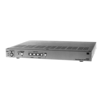
Quad unit
Hide thumbs
Also See for WJ-MS424:
- Operating instructions manual (67 pages) ,
- Specifications (1 page) ,
- Product catalog (125 pages)

Related Manuals for Panasonic WJ-MS424


Summary of Contents for Panasonic WJ-MS424
- Page 1 Quad Unit WJ-MS424 Before attempting to connect or operate this product, please read these instructions completely...
-
Page 2: Table Of Contents
(servicing) instructions Model No. WJ-MS424 in the literature accompanying the appli- ance. Serial No. SA 1966 WARNING: TO PREVENT FIRE OR ELECTRIC SHOCK HAZARD, DO NOT EXPOSE THIS APPLIANCE TO RAIN OR MOISTURE. -
Page 3: Preface
PREFACE the system, and if desired, the monitor can be divided The Panasonic WJ-MS424 Quad Unit is ideal for CCTV into 4 windows for simultaneous display of the four dif- applications where multiple surveillance cameras are ferent images. required. Most 2 : 1 interlace cameras available today,... -
Page 4: Major Operating Controls And Their Functions
MAJOR OPERATING CONTROLS AND THEIR FUNCTIONS VIDEO SELECT ALARM RESET MENU QUAD/SEQ ALARM POWER POWER PROTECTION – CURSOR SELECT Quad System WJ-MS VIDEO VIDEO ALARM/REMOTE SIGNAL GND 1. Power ON/OFF Switch (POWER) • QUAD button This switch turns the power of this switch on or off. When QUAD is selected for VIDEO OUT on the The POWER indicator lights when the power of this SYSTEM SETUP menu, this button works as the... - Page 5 7. Video Output Connectors 4 button: This button moves the cursor to the left or (VIDEO OUT 1, 2, 3, 4) selects an item on the setup menus. 5 button: This button moves the cursor to the right The video input signals connected to the VIDEO IN connector are looped through to these connectors.
-
Page 6: Rack Mounting
RACK MOUNTING To install the WJ-MS424 Quad Unit in an EIA 19-inch 4. Install the unit in the rack with four screws (to be rack, use the rack mounting brackets (provided) and procured locally). eight screws (provided, M3x10). 1. Turn off the power of the unit. -
Page 7: Setting Up The Menus
SETTING UP THE MENUS Before the Settings To select the desired parameter of the selected item, press the SELECT (–, +) buttons. 1. Confirm that the cameras and peripherals are con- nected correctly and firmly. 2. Turn on the power of this unit and connected –... - Page 8 3. Setup Menu Description ALARM RESET VIDEO SELECT MENU QUAD/SEQ ALARM 3-1. SYSTEM SETUP – CURSOR SELECT The SYSTEM menu lets you set the following items: • BORDER • VIDEO OUT • AUTO SKIP • VIDEO LOSS ** SYSTEM SETUP ** 1.
-
Page 9: Alarm Buzzer
3-1-3. Auto Channel Skipping (AUTO SKIP) 3-1-4. Video Loss Checking Setting (VIDEO LOSS) This parameter lets you set automatic skipping of chan- This parameter lets you activate a function that checks nels to which no camera is connected. whether the video signal is being supplied to the VIDEO 1. -
Page 10: Alarm Out
3-3. ALARM OUT ** MAIN ** This parameter lets you adjust the duration the alarm signal is output between 1 and 30 seconds and 1 and 5 SYSTEM SETUP * ALARM BUZZER 2SEC minutes. ALARM OUT 2SEC ALARM AUTO RESET 1. -
Page 11: Title Setup
6. Repeat steps 3 to 5 to determine the sequential order ** TITLE SETUP ** and dwell time. CAM TITLE 7. Press the ESC button to return to the MAIN menu. TITLE SET * TITLE POSI * ALARM TITLE 3-6. TITLE SETUP A title consisting of up to 8 alphanumeric characters can be displayed on the monitor. - Page 12 3-6-4. ALARM TITLE To erase a specific character 1. Select a character to be erased. This parameter lets you decide whether or not to have 2. Select “•” (blank mark) to erase the character. the word”ALARM” displayed when the unit receives the alarm signal.
-
Page 13: System Connections
SYSTEM CONNECTIONS SYSTEM 1 The input video signals for this unit are not synchronized. VIDEO VIDEO VIDEO VIDEO WJ-MS424 VIDEO VIDEO ALARM/REMOTE SIGNAL GND Monitor Monitor Notes : • When pressing the ALARM RESET/QUAD/SEQ/ECS button or the VIDEO SELECT/CURSOR/SELECT buttons, the pic- ture on the video monitor may roll briefly at the time of switching. - Page 14 GENLOCK GENLOCK GENLOCK GENLOCK VIDEO VIDEO VIDEO VIDEO WJ-MS424 VIDEO VIDEO ALARM/REMOTE SIGNAL GND Monitor Monitor Connections • Connect the VIDEO IN connectors of this unit to the video output connectors of the cameras.
- Page 15 VIDEO AUDIO CAMERA VIDEO AUDIO VD/SYNC VD/SYNC (4Vp-p 75 ) WJ-MS424 VIDEO VIDEO ALARM/REMOTE SIGNAL GND Monitor Monitor Note: When pressing the ALARM RESET/QUAD/SEQ/ESC button or the VIDEO SELECT/CURSOR/SELECT buttons, the pic- ture on the video monitor may roll briefly at the time of switching.
- Page 16 SYSTEM 4 Sensor Sensor Sensor Sensor WJ-MS424 VIDEO VIDEO ALARM/REMOTE SIGNAL GND Monitor Monitor Connections • Connect the VIDEO IN connectors of this unit to the video output connectors of the cameras. • Connect the VCR OUT connector of this unit to the input connector of the time lapse VCR.
-
Page 17: Specifications
SPECIFICATIONS Video Input : 2:1 interlace, composite 1V [p-p] 75 , auto termination or loop-through, black and white or color video signal x 4 (Each video signal should be synchronized vertically for vertical interval switching. Does not have to be synchronized in case vertical interval switching is not required.) Video Output : Video Output x 1, composite, 1V [p-p] 75 , color or black and white video signal with com-... - Page 18 Video Imaging Systems Company A Division of Panasonic Broadcast & Television Systems Company A Unit of Matsushita Electric Corporation of America Executive Office: One Panasonic Way 4H-2, Secaucus, New Jersey 07094 Regional Offices: Northeast: One Panasonic Way, Secaucus, NJ 07094 (201) 348-7303...