Honda EB11000 Owner's Manual
Honda generator owner's manual
Hide thumbs
Also See for EB11000:
- Owner's manual (71 pages) ,
- Parts list (13 pages) ,
- Owner's manual (69 pages)
Table of Contents
Advertisement
Advertisement
Table of Contents

Related Manuals for Honda EB11000


Summary of Contents for Honda EB11000
- Page 2 The engine exhaust from this product contains chemicals known of California defects The generator is a potential source of electrical shock if misused. Do not expose the generator to moisture, rain or snow. Do not let the generator get wet, and do not operate Keep this owner's manual handy, so you can refer to it a t any time.
- Page 3 Congratulations on your selection of certain you will be pleased with your purchase of one generators on the market. We want to help you get the best results from your new generator and to operate it safely. This manual contains the information on how to do that;...
- Page 4 A FEW WORDS ABOUT SAFETY Your safety and the safety this generator safely is an important responsibility. To help you make informed decisions about safety, we have provided operating procedures and other information on manual. This information alerts you to potential hazards that could hurt you or others.
-
Page 5: Table Of Contents
SAFETY Safety Label Locations Safety Information COMPONENT IDENTIFICATION CONTROLS Engine Switch Recoil Starter Fuel Valve Choke Knob Circuit Breaker Circuit Protector Ground Fault Circuit Interrupter (GFCI) Hour Meter Auto-throttle Switch Ground Terminal Oil Alert? System GENERATOR USE Connections to a Building Electrical System Ground System Special Requirements AC Applications... - Page 6 MAINTENANCE The Importance of Maintenance Maintenance Safety Emission Control System Information Air Index Maintenance Schedule Engine Oil Change Oil Filter change Air Cleaner Service Spark Plug Service Spark Arrester Maintenance Fuel Sediment Cup Cleaning Fuel Filter Fuse Replacement Battery TRANSPORTING/STORAGE TROUBLESHOOTING WIRING DIAGRAM SPECIFICATIONS...
-
Page 7: Safety
SAFETY LABEL LOCATIONS These labels warn you of potential injury. Read them carefully. If a label comes off or becomes hard to read, contact your Honda generator dealer for a replacement. WARNING You risk electric shock i f you operate generator a faulty GFCl this... - Page 8 A HOT EXHAUST SYSTEM CAN CAUSE SERIOUS BURNS. AVOID CONTACT THE ENGINE HAS BEEN RUNNING.
-
Page 9: Safety Information
SAFETY INFORMATION Honda generators are designed to give safe and dependable service if operated according to instructions. Read and understand this owner's manual before operating your accidents by being familiar with your observing safe operating procedures. Operator Responsibility Know how to stop the generator quickly in Understand the use of all generator controls, output and connections. - Page 10 Electric Shock Hazards The generator produces enough electric power shock or electrocution if misused. Using a generator or electrical appliance in wet conditions, such as rain or snow, or near a pool or sprinkler system, or when your hands are wet, could result in electrocution. Keep the generator dry. If the generator is stored outdoors, unprotected from the weather, check the Ground electrical components on...
-
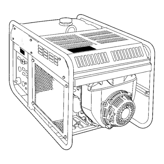
Page 11: Component Identification
COMPONENT IDENTIFICATION TOP COVER OIL FILLER CAP *FRAME SERIAL NUMBER L STARTER GRIP OIL FILTER OIL DRAIN BOLT... - Page 12 SPARK PLUG CAP OIL LEVEL DIPSTICK "Record the engine and frame reference. Refer to these serial numbers when ordering parts, and when making technical or warranty inquiries Frame serial number: Engine serial number: HOOK LIFTING FILTER FUEL serial numbers for your future GROUND TERMINAL (see page 65...
- Page 13 CONTROL PANEL AUTO-THROTTLE SWITCH AC RECEPTACLES 120V 20A AC RECEPTACLES 120V 30A AC RECEPTACLE 120V1240A 30A CIRCUIT PROTECTORS CHOKE KNOB GFCl TEST BUTTON 12OVl24OV) CIRCUIT !JJ)TECTORS CIRCUIT \PROTECTOR 120V) ,CIRCUIT BREAKER...
-
Page 14: Controls
CONTROLS ENGINE SWITCH To start and stop the engine. Key position: OFF: To stop the engine. Key can be removed/inserted. To run the engine after starting. START: To start the engine by operating the starter motor. Return the key to the ON position once the engine has started. Do not use the starter for more than 5 seconds at a time. -
Page 15: Fuel Valve
FUEL VALVE The fuel valve is located between the fuel tank and carburetor. When the valve lever is in the ON position, fuel is allowed to flow from the fuel tank to the carburetor. Be sure to return the fuel valve lever to the OFF position after stopping the engine. -
Page 16: Circuit Breaker
CIRCUIT BREAKER The circuit breaker will automatically switch OFF if there is circuit or a significant overload of the generator at the receptacle, or if the ground-fault circuit interrupter current. Check the following if the circuit breaker switches OFF automatically: When the GFCl RESET button is extended (page 18): -Unplug all appliances from the receptacle and check the appliance for any defects as described in TROUBLESHOOTING (page 62). -
Page 17: Circuit Protector
CIRCUIT PROTECTOR The circuit protectors will automatically switch OFF if there is a short circuit or a significant overload of the generator at the 120V 20A, 120V 30A locking plug, or 120/240V 30A locking plug receptacle. If a circuit protector switches working properly and does not exceed the rated load capacity of the circuit before resetting the circuit protector to the 120V 30A... -
Page 18: Ground Fault Circuit Interrupter (Gfci)
GROUND FAULT CIRCUIT INTERRUPTER (GFCI) Using the generator in rain, snow or near water can lead to death from electric shock. Keep the generator dry. All receptacles on the generator are protected by a ground-fault circuit interrupter (GFCI) for protection against the shock hazard of ground- fault current. - Page 19 Observe the following precautions to ensure proper GFCl operation and to reduce shock hazards: Use grounded 3-conductor extension cords, tools, and appliances, or double-insulated tools and appliances. Inspect cords and plugs, and replace if damaged. Do not use cord lengths greater than 164 feet (50 meters), and do not use multiple tools and appliances with built-in noise filters.
- Page 20 Inspection: Always check GFCl operation before using the generator. You risk electric shock if you operate this generator with a faulty GFCl (ground-fault circuit interrupter). Test GFCl before use. If GFCl fails test, do not use your generator. See your Honda dealer. 1.
- Page 21 6. Press the GFCl RESET button. The RESET button should stay in, flush with its base plate. With the RESET button in breaker to the ON position. The circuit breaker should remain in the ON position. The circuit breaker will not remain in the ON position if the RESET button is extended.
-
Page 22: Hour Meter
HOUR METER The hour meter indicates the hours the generator has been operated. Use it t o determine when scheduled maintenance should be performed (see page41 ). AUTO-THROTTLE SYSTEM The auto-throttle system automatically reduces engine speed when all loads are turned or reconnected, the engine returns to the rated Recommended to minimize fuel consumption and further reduce noise levels when no load... -
Page 23: Ground Terminal
GROUND TERMINAL The generator ground terminal is connected to the frame of the generator, the metal non-current-carrying parts of the generator, and the ground terminals of each receptacle. Before using the ground electrical inspector or local agency having jurisdiction for local codes or ordinances that apply to the intended OIL ALERT@ SYSTEM The Oil Ale@ system is designed to prevent engine damage caused... -
Page 24: Generator Use
GENERATOR USE CONNECTIONS TO A BUILDING ELECTRICAL SYSTEM You should contact a servicing Honda generator dealer for important information before using the E 6 1 1000 with a transfer switch. Connections for standby power to a building electrical system must be made by a qualified electrician. -
Page 25: Ac Applications
AC APPLICATIONS Before connecting an appliance or power cord to the generator: Make sure that it is in good working order. power cords can create a potential for electrical shock. If an appliance begins to operate abnormally, becomes sluggish or stops suddenly, turn it off immediately. -
Page 26: Ac Operation
AC OPERATION Check GFCl operation before each use (see page 18 1. Start the engine (see page33'). 2. Make sure that the GFCl RESET button is pushed in (flush with its base plate). 3. Switch ON the AC circuit breaker. 4. -
Page 27: Ac Receptacle Selection
AC RECEPTACLE SELECTION The generator has separate main ower producing circuits. These two circuits supply equal power Main power circuit Main Circuit I Main Circuit II The table shows the specifications when the 120/240V locking plug receptacle is used for 120V. Example: Receptacle 2 has a 17A load connected to it. -
Page 28: Auto-Throttle Switch
Auto-throttle System With the switch in the reduced when all loads appliances are turned on or reconnected, the engine returns to rated speed. In the OFF position, the auto-throttle system does not operate. The auto-throttle system than 1 ampere. Turn the auto-throttle to the OFF position to operate loads of less than 1 amp. -
Page 29: High Altitude Operation
HIGH ALTITUDE OPERATION At high altitude, the standard carburetor air-fuel mixture will rich. Performance will decrease, and fuel consumption will increase. A very rich mixture will also foul the spark plug and cause hard starting. Operation at an altitude that differs from that at which this engine w certified, for extended periods of time, may increase emissions. -
Page 30: Pre-Operation Check
PRE-OPERATION CHECK ENGINE OIL Check the oil level BEFORE EACH USE with the generator on a level surface and the engine stopped. Use 4-stroke motor oil that meets or exceeds the requirements for API service classification SJ. Al- ways check the API SERVICE label on the oil container to be sure cludes the letters SJ. -
Page 31: Refueling
REFUELING Fuel tank capacity: 6.9 US gal With the engine stopped, check the fuel level gauge. Refill the fuel tank if the fuel level is low. Gasoline is highly flammable and explosive. You can seriously injured when handling fuel. Stop the engine and keep heat, sparks, and flame away. Handle fuel only outdoors. -
Page 32: Fuel Recomendations
FUEL RECOMMENDATIONS Use unleaded gasoline with a pump octane rating of 86 or higher. This engine is certified to operate on unleaded gasoline. Unleaded gasoline produces fewer engine and spark plug deposits and extends exhaust system life. Never use stale or contaminated gasoline or an oil/gasoline mixture. Avoid getting dirt or water in the fuel Occasionally you (metallic rapping noiseywhile operating under heavy loads. - Page 33 Oxygenated Fuels Some conventional gasolines are being blended with alcohol or ether compound. These gasolines are collectively referred to oxygenated fuels. To meet clean air standards, some areas of the United States and Canada use emissions. If you use an oxygenated fuel, be sure it is unleaded and meets the minimum octane rating requirement.
-
Page 34: Battery
BAlTERY The electrolyte level must be level marks. the electrolyte level is near the filler caps and carefully add distilled water to the upper level line (see page The battery contains sulfuric acid corrosive and poisonous. Getting electrolyte in your eyes or burns. -
Page 35: Starting The Engine
STARTING THE ENGINE Electric starting: 1. Make sure that the AC circuit breaker is in the generator may be hard to start if 2. Turn the fuel valve lever to the ON position. 3. Select the choke knob position. -A cold engine: Pull the choke knob to the CLOSED position. - Page 36 Pull starting: 1. Make sure that the generator may be hard to start if 2. Turn the fuel valve lever to the ON position. 3. Pull the choke knob to the CLOSED position. (with a cold and warm engine) 4. Make sure the auto-throttle switch is in the OFF position, or more time will be required for warm up.
-
Page 37: Stopping The Engine
STOPPING THE ENGINE In an emergency: 1. To stop the engine in an emergency, turn the engine switch to the OFF position. In normal use: 1.Turn off the main switch generator. 2. Turn the AC circuit breaker to the OFF position. 3. -
Page 38: Maintenance
MAINTENANCE THE IMPORTANCE OF MAINTENANCE Good maintenance is essential for safe, economical, and trouble- free operation. It will also help reduce air pollution. Improper maintenance, or failure operation, can cause a malfunction in which you can be seriously hurt or killed. Always follow the inspection and maintenance recommendations and schedules in this owner's manual. -
Page 39: Maintenance Safety
MAINTENANCE SAFETY Some of the most important safety precautions follow. However, we cannot warn you of every performing maintenance. Only you should perform a given task. Failure to properly follow maintenance instructions and precautions can cause you to be seriously hurt or killed. Always follow the procedures and precautions in the owner's manual. -
Page 40: Emission Control System Information
EMISSION CONTROL SYSTEM INFORMATION Source of Emissions The combustion process produces carbon monoxide, oxides nitrogen, and hydrocarbons. Control of hydrocarbons and oxides of nitrogen is very important react to form photochemical smog when subjected to sunlight. Carbo monoxide does not react in the same way, but it is toxic. Honda utilizes lean carburetor settings and other systems to reduce the emissions of carbon monoxide, oxides hydrocarbons. - Page 41 Problems That May Affect Emissions If you are aware of any of the following symptoms, have your engine inspected and repaired by your servicing dealer. Hard starting or stalling after starting. Rough idle. Misfiring or backfiring under load. Afterburning (backfiring). exhaust smoke or high fuel consumption.
-
Page 42: Air Index
AIR INDEX An Air Index Information hang tagllabel is applied to engines certified to an emission durability time period in requirements of the California Air The bar graph is intended to provide you, our customer, the ability to compare the emissions performance of available engines. The lower the Air Index, the less pollution. -
Page 43: Maintenance Schedule
MAINTENANCE SCHEDULE Perform at every indicated month Fuel tank Clean Fuel filter Check Replace Fuel tube Check NOTE: Emission related items. (*)Replace the paper air filter only. (1)Service more frequently when used i n dusty areas. (2)These items should be serviced by your servicing proper tools and are mechanically proficient. -
Page 44: Engine Oil Change
ENGINE OIL CHANGE Drain the oil while the engine is warm to assure rapid and complete draining. Open the top cover to access the oil filler cap. 2. Remove the oil filler cap and oil drain bolt, and drain the oil into a suitable container. -
Page 45: Oil Filter Change
OIL FILTER CHANGE 1. Drain the engine oil, and retighten the drain bolt securely (see page 42 ). 2. Remove the front cover to acsess the oil filter. 3. Remove the oil filter, and drain the oil into Discard the used oil filter. 4.Clean the filter mounting base, and coat the O-ring of the new oil filter with clean engine oil. -
Page 46: Air Cleaner Service
AIR CLEANER SERVICE A dirty air filter will restrict air flow to the carburetor malfunction, service the air cleaner regularly. Service more frequently when operating the generator in extremely dusty areas. NOTICE Never run the generator without the air filter. Rapid engine wear will result. - Page 47 5. Inspect both air filters, and Always replace the paper air filter a t the scheduled interval page 41 6. Clean the air filters if they Paper air filter: Tap the paper air filter several times on a hard surface to remove dirt, or blow compressed air [not exceeding 30 psi (207 kPa, 2.1 kgfkm’)] through the air cleaner case side.
-
Page 48: Spark Plug Service
SPARK PLUG SERVICE In order to service the spark plug, you will need a spark plug wrench (commercially available). Recommended spark plugs: ZGR5A (NGK) To ensure proper engine operation, the spark plugs must gapped and free of deposits. If the engine has been running, the exhaust pipe and muffler very hot. - Page 49 6. Check that the spark plug washers are in good condition, and thread the spark plugs in by hand to prevent cross-threading. 7. After the spark plugs are seated, tighten with a spark plug wrench to compress the washer. If installing a new spark plug, tighten 1/2 turn after the spark plug seats to compress the washer.
-
Page 50: Spark Arrester Maintenance
SPARK ARRESTER MAINTENANCE If the generator has been running, the muffler to cool before proceeding. must The spark arrester efficiency. Remove the special screw, and remove the spark arrester from the muffler. 2. Use a brush to remove carbon deposits from the screen. -
Page 51: Fuel Sediment Cup Cleaning
FUEL SEDIMENT CUP CLEANING The sediment cup prevents dirt or water which may from entering the carburetor. If the engine has not been run for a long time, the sediment cup should be cleaned. 1. Turn the engine switch to the 2. -
Page 52: Fuel Filter
FUEL FILTER 1. Check the fuel filter for water accumulation or sediment. FUEL FILTER 2. If the fuel filter is found with excessive water accumulation or sediment, take the generator to your servicing dealer. -
Page 53: Fuse Replacement
FUSE REPLACEMENT Turn the engine switch OFF and remove the key before checking or replacing fuses to prevent accidental short-circuiting. Remove the fuse holder cover and with rating that specified. MAIN FUSE: SUB FUSE: If frequent fuse failure occurs, determine the cause and correct the problem before attempting to operate the generator further. -
Page 54: Battery
BATTERY The battery contains sulfuric acid corrosive and poisonous. Getting electrolyte in your eyes or on your skin can cause serious burns. Wear protective clothing and eye protection when working near the battery. EMERGENCY PROCEDURES: Eyes-Flush with water from a cup or other container for a t least 15 minutes (water under pressure can damage the eye). - Page 55 Removal Remove the front cover to access the battery. FRONT COVER 2.Remove the negative terminal; then remove the positive positive terminal. BAlTERY SET PLATE 3. Remove the battery set plate. 4. Remove the battery from the battery tray. cable from the battery ne ative ( - ) (+) cable from t NEGATIVE (-) CABLE...
- Page 56 Installation 1. Install the battery tray in the generator, and the battery on the 2.Make sure the battery is on the edge of the battery tray of the fuse holder side. Install the battery set plate. 3.1nstall the positive ( + ) cable to the battery positive (+) terminal, make sure t o cover the terminal with the terminal the negative cable to the battery negative ( - ) terminal.
- Page 57 Refilling Battery Fluid If the generator is operated sulfation and battery plate damage will occur. If rapid loss of electrolyte is experienced, or if your battery seems to be weak, causing slow starting or other authorized Honda generator dealer. 1. Remove the front cover and the battery (see pages 52 2.Check the electrolyte level in each battery cell.
- Page 58 Charging The generator's engine has an approximate 3-amp charging system to charge the battery while the engine is running. If the generator is only used periodically, the battery must be charged monthly maintain the battery service life. A lead acid battery self discharges a t a rate of 0.5- 1 .O% per day. This means that the battery, if the generator is not operated in a month, can discharge as much as 30% in the same period.
- Page 59 TRANSPORTING If the generator has been used, allow it cool for at least 15 minutes before loading the generator on the transport vehicle. and exhaust system can burn you and can ignite some material. When transporting the generator, turn the engine switch and the fuel valve OFF, and keep the generator level to reduce the possibility of fuel leakage.
- Page 60 STORAGE Before storing the unit for an extended period: Be sure the storage area is free of excessive humidity and dust. 2. Service according to the table below: STORAGETIME Less than 1 month to 2 months months to year year or more Use gasoline conditioners that are formulated to extend storage life.
- Page 61 Storage Procedure 1. Drain the fuel. a.Remove the fuel tank cup, and empty the fuel tank gasoline container using the fuel tank cap. Gasoline is highly flammable and explosive. You can be seriously injured when handling fuel. Stop the engine and keep heat, sparks, and flame away. Handle fuel only outdoors.
- Page 62 out the carburetor drain tube end under the fan cover of the engine, b.Pull and place suitable container. Loosen the carburetor drain screw. d.Drain the gasoline from the carburetor into the container. e.Tighten the carburetor drain screw securely. CARBURETOR DRAIN SCREW CARBURETOR DRAIN TUBE 2.Change the engine oil (page 42 3.Remove the two spark plugs and pour about a tablespoon of clean...
-
Page 63: Troubleshooting
When the engine will not start: there fuel in the tank? there enough oil in the engine? Is there a spark f r o m t h e s p a r k plugs? Be sure there is the generator to an 2)Fuel should flow TROUBLESHOOTING Still NO spark R e p l a c e... - Page 64 No electricity at the AC receptacles: (When the GFCl RESET button is extended) Unplug all appliances and equipment, and in- spect the GFCl operation. (refer to page 18) The G F C ~ RESET button not extended. (When the GFCl RESET button is not extended) IS the AC circuit breaker NO Is the AC circuit protector Check the electrical ap-...
-
Page 65: Wiring Diagram
WIRING DIAGRAM 1"... -
Page 66: Specifications
SPECIFICATIONS Dimensions Model (Type) Length Width Height Dry weight ingine Model Engine Type Displacement [Bore x Stroke] Speed Cooling System Engine Oil Refill Capacities Fuel Tank Capacity Spark Plug senerator Model TY Pe Rated voltaae Rated frequency AC output Rated Ampere Rated Output Maximum Output Tune-up... -
Page 67: Warranty Service Information
The Service Manager or General Manager can help. Almost all problems If you are dissatisfied with the decision made management, contact the Honda Power Equipment Customer Relations Office. You can write to: American Honda Motor Co., Inc. -
Page 68: Index
COMPONENT IDENTIFICATION CONTENTS CONTROLS Auto-throttle Switch Choke Knob Circuit Breaker Circuit Protector Engine Switch Fuel Valve Ground Fault Circuit Interrupter (GFCI) Ground Terminal Hour Meter Oil Ale@ System Recoil Starter GENERATOR USE AC Applications Operation ... AC Receptacle Selection Auto-throttle System Connections to a Building Electrical System Ground System High Altitude Operation... - Page 69 SAFETY Safety Information Safety Label Locations SPECIFICATIONS STARTING THE ENGINE STOPPING THE TRANSPORTlNG/STORAGE TROUBLESHOOTING WARRANTY SERVICE INFORMATION WIRING DIAGRAM ENGINE...
- Page 70 MEMO...