Table of Contents
Advertisement
SIMATIC
ET 200L, ET 200L-SC and
ET 200L-SC IM-SC
Distributed I/O Device
Manual
EWA 4NEB 780 6009-02c
Edition 04
Preface, Contents
Product Overview
Installation
Wiring
Commissioning
Diagnostics
General Technical Data
Terminal Blocks and Supplemen-
tary Terminals – Technical Data
ET 200L Electronics Blocks –
Technical Data
ET 200L-SC Electronics Blocks –
Technical Data
SC Digital Electronic Modules –
Technical Data
SC Analog Electronic Modules –
Parameters
SC Analog Electronic Modules –
Technical Data
SC 1COUNT40kHz Counter
Module
Order Numbers
Type and Device Master Files
Configuration Frame and
Parameterization Frame
ESD
Glossary, Index
1
2
3
4
5
6
7
8
9
10
11
12
13
A
B
C
D
Advertisement
Table of Contents

Related Manuals for Siemens Metro 21 M216KA


Summary of Contents for Siemens Metro 21 M216KA
- Page 1 Preface, Contents Product Overview Installation Wiring SIMATIC Commissioning ET 200L, ET 200L-SC and Diagnostics ET 200L-SC IM-SC General Technical Data Distributed I/O Device Terminal Blocks and Supplemen- tary Terminals – Technical Data Manual ET 200L Electronics Blocks – Technical Data ET 200L-SC Electronics Blocks –...
-
Page 2: Edition
Safety Guidelines This manual contains notices which you should observe to ensure your own personal safety, as well as to protect the product and connected equipment. These notices are highlighted in the manual by a warning triangle and are marked as follows according to the level of danger: Danger indicates that death, severe personal injury or substantial property damage will result if proper precautions are not taken. - Page 3 Preface Purpose of the The information in this manual will enable you to run the ET 200L distrib- Manual uted I/O device and Smart Connect SC in the ET 200 distributed I/O system as a DP slave. Contents of the Order number 6ES7 130-1AA00-8AA0 comprises the manual Manual ET 200L, ET 200L-SC and ET 200L-SC IM-SC...
- Page 4 Preface Standards and The ET 200L and Smart Connect SC meet the requirements and and criteria Certification of IEC 1131, Part 2 and are based on the EN 50170 Volume 2, PROFIBUS standard. They meet the requirements for the CE marking, and have CSA, UL and FM certification.
- Page 5 Preface Aids to Using the To enable you to access the information you require as quickly as possible, Manual the manual contains the following aids: At the beginning of the manual you will find a complete table of contents and lists of all the figures and tables in the manual. In the left-hand margin in each chapter you will find headings that pro- vide you with an overview of the contents of the various sections .
- Page 6 Preface Constantly You can get constantly updated information on SIMATIC products: Updated On the Internet at http://www.ad.siemens.de/ Information On the fax polling no. +49 8765-93 00 50 00 In addition, SIMATIC Customer Support provides you with current informa- tion and downloads that can be useful to you when using SIMATIC products: On the Internet at http://www.ad.siemens.de/support/html_00/index.shtml At the SIMATIC Customer Support mailbox on +49 (911) 895-7100 To access the mailbox, use a modem of up to V.34 (28.8 kbps) with the...
-
Page 7: Table Of Contents
Contents Preface Contents Product Overview ............What Is the ET 200 Distributed I/O System? . - Page 8 Contents Commissioning ............Configuration Software .
- Page 9 Contents Electronics Block L 16 DI/16 DO DC 24 V/0.5 A – 6ES7 133-1BL00-0XB0 8-15 Electronics Block L 16 DI AC 120 V – 6ES7 131-1EH00-0XB0 ..8-18 Electronics Block L 16 DO AC 120 V/1.0 A – 6ES7 132-1EH00-0XB0 .
- Page 10 Contents 11.14 Default Parameters of the Analog Output Modules ....11-22 11.15 Behavior of the Analog Output Modules ......11-23 11.16 Conversion, Cycle, Settling and Response Times of the Analog...
- Page 11 Contents 13.4 Wiring the Counter and Putting the Counter into Operation ... . 13-14 13.4.1 Wiring the Counter ..........13-15 13.4.2 Putting the Counter into Operation...
- Page 12 Contents Figures A Typical PROFIBUS-DP Installation ....... View of the ET 200L Distributed I/O Device .
- Page 13 Contents View of the L 16 DI DC 24 V Electronics Block ..... . . Block Diagram of the L 16 DI DC 24 V Electronics Block .
- Page 14 Contents 11-3 Connecting Insulated Thermocouples of the Same Type with External Com- pensation, via a Resistance Thermometer Connected to the Resistance Mea- surement Module, to Slot A of the Terminal Block (Example TB 16SC) 11-13 11-4 Connecting Voltage Sensors (Example TB 16SC) .
- Page 15 Contents 13-8 Periodic Upward Counting ......... 13-6 13-9 Periodic Downward Counting...
- Page 16 Contents Tables General Components for the ET 200L, ET 200L-SC, ET 200L-SC IM-SC Components of the ET 200L Distributed I/O Device ....Components of a ET 200L-SC .
- Page 17 Contents 11-21 Life-Zero Output Ranges ......... . 11-51 12-1 Static Parameters of the 2 AI U Electronic Module...
- Page 18 Contents ET 200L, ET 200L-SC and ET 200L-SC IM-SC Distributed I/O Device xviii EWA 4NEB 780 6009-02c...
-
Page 19: Product Overview
Product Overview In This Chapter The product overview provides information about The role of the ET 200L distributed I/O device and Smart Connect within the ET 200 distributed I/O system. The components which make up the ET 200L distributed I/O device. The components which make up the Smart Connect SC. -
Page 20: What Is The Et 200 Distributed I/O System
Product Overview What Is the ET 200 Distributed I/O System? What Is the When a system is installed, the input/output modules are normally installed ET 200? centrally in the programmable logic controller. If inputs and outputs are made at long distances from the programmable logic controller, there may be long runs of cabling which are not immediately com- prehensible, and electromagnetic interference may impair reliability. -
Page 21: What Is The Et 200L Distributed I/O Device And Smart Connect
Product Overview What Is the ET 200L Distributed I/O Device and Smart Connect? Definition The ET 200L distributed I/O device and Smart Connect is a DP slave within the ET 200 distributed I/O system, its degree of protection being IP 20. Applications Owing to its compact and flat design, the ET 200L distributed I/O device and Smart Connect is particularly suitable for applications in which space is at a... - Page 22 Product Overview ET 200L-SC The ET 200L-SC modular I/O device can be upgraded with the SIMATIC Modular I/O Device Smart Connect. The ET 200L-SC also consists of a terminal block to which an electronics block is connected. The electronics block has an interface for connecting the SIMATIC Smart Connect.
- Page 23 Product Overview ET 200L-SC IM-SC The ET 200L-SC IM-SC fine-step modular I/O device can be upgraded with Fine-Step Modular the SIMATIC Smart Connect. I/O Device The ET 200L-SC IM-SC consists of a TB 16IM-SC terminal block to which you can connect the IM-SC interface module and up to 8 Smart Connect electronic modules.
-
Page 24: General Components For The Et 200L, Et 200L-Sc, Et 200L-Sc Im-Sc
Product Overview General A range of components are available for setting up the ET 200L, Components for ET 200L-SC or ET 200L-SC IM-SC. You will find the components that you the ET 200L, require for all versions of the ET 200L in Table 1-1. ET 200L-SC, You will find other components in Sections 1.2.1 to 1.2.3. - Page 25 Product Overview Terminal Block The terminal block (TB) is used for mounting the electronics block (EB). It contains the wiring so that if the electronics block is replaced, leads do not have to be loosened. The terminal block is characterized by the following: It can be pre-wired before the electronics block is mounted.
-
Page 26: What Is The Et 200L Block I/O Device
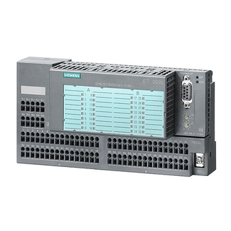
Product Overview 1.2.1 What Is the ET 200L Block I/O Device? Features of the Figure 1-2 shows you a view of the ET 200L distributed I/O device. It con- ET 200L sists of a terminal block and an electronics block. Electronics block Terminal block Figure 1-2... -
Page 27: Components Of The Et 200L Distributed I/O Device
Product Overview ET 200L A whole range of components is available for installing and commissioning Components the ET 200L. The most important components and their functions are listed in Table 1-2: Table 1-2 Components of the ET 200L Distributed I/O Device Component Function Illustration... -
Page 28: What Is The Et 200L-Sc Modular I/O Device
Product Overview 1.2.2 What Is the ET 200L-SC Modular I/O Device? ET 200L-SC The modules of the ET 200L-SC can be upgraded with a Smart Connect. The Modules modules of the ET 200L-SC include: 24 V DC digital input modules 24 V DC digital output modules 24 V DC digital input and output modules Smart Connect SC... -
Page 29: Components Of A Et 200L-Sc
Product Overview Table 1-3 Components of a ET 200L-SC Component Function Illustration TB 16L, TB32L terminal block ...carries the wiring and accepts the electronics block. – With spring terminal – With screw-type terminal Electronics block for the SC ...is mounted on the terminal block. - Page 30 Product Overview Table 1-3 Components of a ET 200L-SC, continued Component Function Illustration Shield terminal ...connects the shielding of ana- log signal lines with the supple- mentary terminal. Labeling sheet ...allows the labeling strips to be labeled automatically or printed using a laser printer.
-
Page 31: What Is The Et 200L-Sc Im-Sc Fine-Step Modular I/O Device
Product Overview 1.2.3 What Is the ET 200L-SC IM-SC Fine-Step Modular I/O Device? Features of the The ET 200L-SC IM-SC consists of the TB 16IM-SC terminal block, to ET 200L-SC IM-SC which the IM-SC interface module and up to 8 Smart Connect electronic modules are connected. -
Page 32: Components Of An Et 200L-Sc Im-Sc
Product Overview Expanding the The ET 200L-SC IM-SC can be expanded by means of a TB 16SC terminal ET 200L-SC IM-SC block to connect 8 additional SC electronic modules. High-Speed These modules offer high-speed measured-value acquisition and data transfer. Analog Input They are particularly well suited to rapid data acquisition for pressure and Modules flow measurements. - Page 33 Product Overview Table 1-4 Components of an ET 200L-SC IM-SC Component Function Illustration Supplementary terminal, single- ...is an extension for actuators tier and sensors with a 3-wire con- nection. – Spring terminal – Screw-type terminal Supplementary terminal, two- ...is an extension for actuators tier and sensors with a 4-wire con- nection.
- Page 34 Product Overview ET 200L, ET 200L-SC and ET 200L-SC IM-SC Distributed I/O Device 1-16 EWA 4NEB 780 6009-02c...
-
Page 35: Installation
Installation Introduction The ET 200L distributed I/O device and Smart Connect has been designed for simple installation and wiring. To this end, the label of the ET 200L dis- tributed I/O device and Smart Connect has been made self-explanatory. In this chapter, you will find additional information on installing and wiring the ET 200L distributed I/O device and Smart Connect. - Page 36 Installation Contents of the Section Topic Page Chapter Installing the ET 200L TB 16L/TB 32L Terminal Block and Supplementary Terminal Installing and Disassembling the ET 200L Electronics Block Installing the TB 16IM-SC/TB 16SC Terminal Block Connecting the Smart Connect Electronic Modules to the 2-13 TB 16IM-SC/TB 16SC Terminal Block Installing the ET 200L IM-SC Interface Module on the...
-
Page 37: Installing The Et 200L Tb 16L/Tb 32L Terminal Block And Supplementary Terminal
Installation Installing the ET 200L TB 16L/TB 32L Terminal Block and Supplementary Terminal Introduction In this section, we describe how you install the terminal block and the sup- plementary terminal. Requirements Install the terminal block on a rail. You install the ET 200L distributed I/O device on a rail conforming with EN 50022 (35 7.5 or 35 15). -
Page 38: Installing The Terminal Block
Installation Installing the Install the terminal block in the following order: Terminal Block 1. Mount the terminal block on the rail. 2. Tilt the terminal block backwards until you hear both the safety bolts en- gage. You can now wire the terminal block (refer to Chapter 3) before you install the electronics block. -
Page 39: Disassembling The Terminal Block
Installation Disassembling the Remove the terminal block in the following order (refer also to Figure 2-2): Terminal Block 1. Turn off the power supply. 2. Remove the electronics block. – Remove the bus connector. – Loosen the fixing screw. – Tilt the electronics block forwards. 3. -
Page 40: Installing And Disassembling The Et 200L Electronics Block
Installation Installing and Disassembling the ET 200L Electronics Block Installing the Attach the electronics block to the terminal block in the following order: Electronics Block 1. Insert the electronics block from above into the guideways on the termi- nal block. 2. -
Page 41: Installing The Tb 16Im-Sc/Tb 16Sc Terminal Block
Installation Installing the TB 16IM-SC/TB 16SC Terminal Block Installation The terminal blocks are intended for installation in a cabinet or in an en- closed casing or operating room. The TB 16SC and TB 16IM-SC terminal blocks can be installed horizontally. Provided temperatures do not exceed 40 C, other installation locations are also possible. -
Page 42: Snapping The Terminal Block Onto The Rail
Installation Installing the Proceed as follows: Terminal Block 1. Mount the terminal block in such a way that sufficient clearance remains for ventilating the terminal block and installing and ventilating the elec- tronic modules. 2. Screw the rail (35 mm wide) to the cabinet frame or the mounting block (screw size: M5). -
Page 43: Sliding The Labeling Strip Into The Terminal Block
Installation Sliding the Proceed as follows: Labeling Strips 1. Note the assignment between the slot and the module on the labeling into the Terminal strip. Block 2. Slide the labeling strip from the side into the terminal block guide. Figure 2-5 Sliding the Labeling Strip into the Terminal Block ET 200L, ET 200L-SC and ET 200L-SC IM-SC Distributed I/O Device EWA 4NEB 780 6009-02c... - Page 44 Installation Positioning the You must now position the coding slide switches correctly in accordance with Coding Slide the configuration of your system so that you can install the electronic mod- Switches ules. Each slot has a coding slide switch. The terminal blocks are supplied with coding slide switches at position 0.
-
Page 45: Positioning The Coding Slide Switches
Installation Coding slide switches Figure 2-6 Positioning the Coding Slide Switches 1. Select a screwdriver with a blade width of 3.5 mm. 2. Insert the screwdriver into the slot on the coding slide switch (see Fig- ure 2-7). 3. Apply slight pressure to push the coding slide switch into the required position. -
Page 46: Designation Plate With Labeling Strips (Reduced In Size)
Installation Noting the System Note your system designations on the enclosed labeling strip for the elec- Designation tronic module. Separating edges Labeling strips for electronic modules Labeling strips for terminal block and supplementary termi- nal can be truncated here Figure 2-8 Designation Plate with Labeling Strips (Reduced in Size) ET 200L, ET 200L-SC and ET 200L-SC IM-SC Distributed I/O Device 2-12... -
Page 47: Connecting Smart Connect Electronic Modules To The Tb 16Im-Sc/Tb 16Sc Terminal Block
Installation Connecting Smart Connect Electronic Modules to the TB 16IM-SC/TB 16SC Terminal Block Connection Rules The following connection rules apply to the SC electronic modules: for the Electronic You can connect up to 10 counter modules in an ET 200L-SC IM-SC Modules (with TB 16SC). -
Page 48: Et 200L-Sc Im-Sc
Installation Number of Plug-in The number of plug-in analog SC electronic modules is limited in the follow- Analog SC ing cases: Electronic – When there is no S7 DP master Modules – When they are used in an ET 200L-SC IM-SC with a TB 16SC con- nected The PROFIBUS-DP standard EN 50 170, Volume 2, restricts the length of the parameterization data to a maximum of 244 bytes. - Page 49 Installation Labeling Strips of Slide the labeling strip down from the top into the electronic module to be the Electronic plugged in. Modules Note You will only achieve full operating safety of the electronic modules if you have inserted the labeling strips on the front of the electronic modules (elec- trostatic discharge on the front of the module, covering the LEDs).
- Page 50 Installation Warning There is a risk of injury and damage to property. When using AC modules, you must use a supplementary terminal (screw- type terminal), to which you must connect the protective conductor. When using AC modules, you must use screw-type supplementary termi- nals.
-
Page 51: Installing The Et 200L Im-Sc Interface Module On The Tb 16Im-Sc Terminal Block
Installation Installing the ET 200L IM-SC Interface Module on the TB 16IM-SC Terminal Block Requirements Before you install the IM-SC interface module on the TB 16IM-SC terminal block, note the following: The screw for fixing the IM-SC interface module is shipped screwed into the terminal block. -
Page 52: Setting The Et 200L Profibus Address
Installation Setting the ET 200L PROFIBUS Address Introduction The PROFIBUS address defines the address of the ET 200L distributed I/O device on the PROFIBUS-DP. Location of Rotary The two rotary switches for the PROFIBUS address are located on the elec- Switches tronics block beneath the bus connector. -
Page 53: Installing A Supplementary Terminal And Shield Terminal On The Tb 16Im-Sc/Tb 16Sc Terminal Block
Installation Installing a supplementary terminal and shield terminal on the TB 16IM-SC/TB 16SC terminal block Securing the If you want to connect a single-tier or two-tier supplementary terminal, pro- Supplementary ceed as follows: Terminal to the 1. Hold the supplementary terminal parallel to the terminal block. Use the Terminal Block right edge as a guide. -
Page 54: Connecting A Shield Terminal To The Supplementary Terminal
Installation Shielding for In analog processing, you insert the cables of the signal lines in the shield Analog Processing terminal. To do this, proceed as follows: 1. Clip the TB 16IM-SC/TB 16SC terminal block onto the rail. 2. Connect a 1- or 2-tier supplementary terminal to the TB 16IM-SC/ TB 16SC terminal block. - Page 55 Installation 4. Secure the shield terminal in the supplementary terminal by tightening the screw of the slot with a screwdriver. 5. If you are using a TB 16IM-SC/TB 16 SC (screw-type terminal): Secure the shield terminal in the supplementary terminal by tightening the screw of the slot with a screwdriver.
- Page 56 Installation ET 200L, ET 200L-SC and ET 200L-SC IM-SC Distributed I/O Device 2-22 EWA 4NEB 780 6009-02c...
-
Page 57: Wiring
Wiring Introduction The ET 200L distributed I/O device and Smart Connect has been designed for simple wiring. To this end, the label of the ET 200L distributed I/O de- vice and Smart Connect has been made self-explanatory. In this chapter, you will find additional information on wiring the ET 200L distributed I/O device and Smart Connect. - Page 58 Wiring Contents of the Section Topic Page Chapter General Rules and Regulations Configuring the Electrical Installation Wiring Rules Wiring the ET 200L TB 16L/TB 32L Terminal Block 3-11 Wiring the Smart Connect TB 16SC Terminal Block 3-14 Wiring the ET 200L TB 16IM-SC Terminal Block 3-16 Wiring the ET 200L IM-SC Interface Module 3-18...
-
Page 59: General Rules And Regulations
Wiring General Rules and Regulations Introduction As a component part of a plant or system, the ET 200L distributed I/O device necessitates observance of special rules and regulations, depending on where it is to be used. This section provides an overview of the most important rules which you have to observe for integrating the ET 200L distributed I/O device in a plant or system. - Page 60 Wiring 24 VDC Supply The following table shows the points that you have to take into account in respect of the 24 VDC supply. With ... Pay Attention to... Buildings Outdoor lightning Take lightning protec- protection tion precautions – for example, lightning l li ht i 24 VDC supply lines,...
-
Page 61: Configuring The Electrical Installation
Wiring Configuring the Electrical Installation Introduction In this section, you will find information on the overall installation of an ET 200L distributed I/O device and Smart Connect on a grounded supply (TN-S system). The specific topics discussed are: Circuit-breaking devices, short-circuit and overload protection in accor- dance with DIN VDE 0100 and DIN VDE 0113 Load current power supplies and load circuits. - Page 62 Wiring Characteristics of The load current power supply feeds input and output circuits (load circuits) Load Current as well as sensors and actuators. The following table lists the characteristics Power Supplies of load current power supplies that are required in specific applications. Characteristic of Required for ...
-
Page 63: Operating The Et 200L From A Grounded Supply
Wiring ET 200L in Overall Figure 3-1 shows the location of the ET 200L in the overall system (load cur- Installation rent voltage supply and grounding philosophy) for supply from a TN-S sys- tem. Remark: The arrangement of the power supply connections shown in the fig- ure does not correspond to the actual arrangement but was chosen for the sake of clarity. -
Page 64: Power Supply Of The Terminal Block
Wiring Smart Connect in Only safely isolated low voltage (DC 24 V) can be used as the power supply. Overall Installation Safe isolation from the mains supply can be achieved in accordance with the requirements in VDE 0100 Part 410 / HD 384-4-41 / IEC 364-4-41 (as func- tional low voltage with safe isolation) or VDE 0805 / EN 60950 / IEC 950 (as safety extralow voltage with safe isolation SELV) or VDE 0106 Part 101. -
Page 65: Wiring Rules
Wiring Wiring Rules Rules for Wiring The table below shows you what you must observe when wiring the terminal block and the supplementary terminal. Table 3-2 Pinout of the PROFIBUS-DP Terminal Connection Rules for ... Terminal block Spring Terminal Screw-Type Terminal Suitable cable cross-sections: Solid cables 0.14 to 1.5 mm... -
Page 66: How The Spring Terminal Works
Wiring Terminal Block To wire the terminal block (spring terminal), proceed as follows: with Spring 1. Strip the insulation of the wires down to 11 mm. Terminal Remember to: Insert the screwdriver in the lower opening. Insert the cable in the upper opening until the stop. 1. -
Page 67: Wiring The Et 200L Tb 16L/Tb 32L Terminal Block
Wiring Wiring the ET 200L TB 16L/TB 32L Terminal Block Introduction When wiring the ET 200L distributed I/O device, we distinguish between the terminal block with its supplementary terminal and the electronics block. The terminal block and, if required, the supplementary terminal carry the wiring. -
Page 68: Alternative Ways Of Connecting The Voltage Supply
Wiring Connecting the There are three different ways to connect the voltage supply to the terminal Voltage Supply block. 1st alternative 2nd alternative 3rd alternative Shared voltage supply for Shared voltage supply for Separate voltage supply for groups of channels electronics and groups of each group of channels channels... -
Page 69: Pinout Of The Profibus-Dp Terminal Connection
Wiring PROFIBUS-DP The table below describes the pinout of the 9-pin PROFIBUS-DP terminal Terminal connection. Connection Table 3-3 Pinout of the PROFIBUS-DP Terminal Connection View Pin No. Signal Name Description – – – – RxD/TxD-P Data line B Request To Send M5V2 Data reference potential (from station) P5V2... -
Page 70: Wiring The Smart Connect Tb 16Sc Terminal Block
Wiring Wiring the Smart Connect TB 16SC Terminal Block Introduction The TB 16SC terminal block and – if required – the supplementary terminal carry the wiring. Wiring the The figure below shows the connections of the TB 16SC terminal block: TB 16SC Figure 3-6 Front View of the Terminal Block... - Page 71 Wiring TB 16SC Terminal The following table contains an example of the assignment of terminals to Designation slots. Slot Terminals 1L+; 2L+ 1M; 2M Slot A (on the extreme left) A1;A2;A3;A4 Slot B B1;B2;B3;B4 Slot C C1;C2;C3:C4 Slot D D1;D2;D3;D4 Slot E E1;E2;E3;E4 Slot F...
-
Page 72: Wiring The Et 200L Tb 16Im-Sc Terminal Block
Wiring Wiring the ET 200L TB 16IM-SC Terminal Block Introduction The TB 16IM-SC terminal block and – if required – the supplementary termi- nal carry the wiring. The TB 16IM-SC terminal block also has an interface to the Smart Connect. Wiring the The figure below shows the connection of the TB 16IM-SC terminal block: TB16 IM-SC... -
Page 73: Connection Alternatives For The Power Supply
Wiring Connecting the There are two different ways to connect the voltage supply to the terminal Power Supply block. 3rd alternative 1st alternative 2nd alternative TB 16IM-SC TB 16IM-SC TB 16IM-SC 3L+ 3M 3L+ 3M 3L+ 3M IM-SC IM-SC IM-SC Separate power supply for the TB Shared power supply for the TB 16IM- Shared power supply for the IM-SC... -
Page 74: Wiring The Et 200L Im-Sc Interface Module
Wiring Wiring the ET 200L IM-SC Interface Module Introduction The IM-SC connects the TB 16IM-SC terminal block to the PROFIBUS-DP. Wiring the IM-SC The figure below shows all the connections of the IM-SC interface module: Bus terminating switch Connection for power supply Connection for... -
Page 75: Assignment Of The Profibus-Dp Connection At The Im-Sc Interface Module
Wiring IM-SC PROFIBUS- A plug-in, 6-pin screw-type terminal with a shield support connects the DP Connection ET 200L-SC IM-SC to the PROFIBUS-DP. You can connect the bus lines and the shield to the screw-type terminal. The 6-pin screw-type terminal is shipped with the IM-SC interface module. Table 3-4 Assignment of the PROFIBUS-DP Connection at the IM-SC Interface Module View... -
Page 76: Length Of Insulation Stripped
Wiring Wiring the The bus lines (see Appendix A) are connected to the plug-in, multipole PROFIBUS-DP screw-type terminal. Connection Note When you remove the PROFIBUS-DP screw-type terminal, the subsequent DP slaves are disconnected from the PROFIBUS-DP. 1. Strip the insulation from the bus line as shown in the figure below. 22 mm 7 mm 6.5 mm... -
Page 77: Connecting The Power Supply
Wiring Power Supply You connect the power supply for the electronics to the plug-in, 4-pole screw-type terminal. The 4L+, 5L+ and 4M, 5M terminals are linked inter- nally. This enables the power supply to be looped through via the 5L+ and 5M terminals. -
Page 78: Using The Supplementary Terminal For The Tb 16Sc/Tb 16Im-Sc
Wiring Using the Supplementary Terminal for the TB 16SC/TB 16IM-SC Possible Uses of The terminals are electrically connected to each other internally. You can use the Single-Tier the single-tier supplementary terminal for different purposes. You must adapt Supplementary the labeling of the supplementary terminal according to the application. Terminal 1. -
Page 79: Connecting Shielded Lines To The Shield Terminal Of The Supplementary Terminals
Wiring Connecting Shielded Lines to the Shield Terminal of the Supplementary Terminals Application The shield terminal makes it easy to connect to ground all shielded cables that lead to or from electronic modules of the Smart Connect. You obtain a connection to ground by installing the shield terminal in the supplementary terminal and connecting it to local ground at low resistance. -
Page 80: Connecting The Smart Connect Sc To The Et 200L-Sc/Tb 16Im-Sc
Wiring 3.10 Connecting the Smart Connect SC to the ET 200L-SC/TB 16IM-SC Introduction The electronics blocks of the ET 200L-SC and the ET 200L-SC IM-SC can all be supplemented by means of the Smart Connect: – ET 200L-SC 16 DI DC 24 V 6ES7 131-1BH11-0XB0 –... -
Page 81: Commissioning
Commissioning Contents of the Section Topic Page Chapter Configuration Software Commissioning the ET 200L and Smart Connect Replacing SC Electronic Modules ET 200L, ET 200L-SC and ET 200L-SC IM-SC Distributed I/O Device EWA 4NEB 780 6009-02c... -
Page 82: Configuration Software
Commissioning Configuration Software ET 200L You configure the ET 200L distributed I/O device and SC using the following configuration software. COM ET 200 Windows as of Version 1.0 COM PROFIBUS as of Version 3.0 STEP 7 as of Version 2.1 You will find the name of the type file for the various electronics blocks and the contents of the device master file described in Appendix C. -
Page 83: Commissioning The Et 200L And Smart Connect
Commissioning Commissioning the ET 200L and Smart Connect Commissioning Commission the ET 200L distributed I/O device as follows: the ET 200L Step Activity Explanation Install and wire up the ET 200L. You will find detailed instructions on instal- ling and wiring in Chapters 2 and 3. The two rotary switches used to set the Set the PROFIBUS address of the ET 200L. - Page 84 Commissioning Start-up The ET 200L distributed I/O device and Smart Connect starts up automati- cally when the power supply is turned on. A separate switch is not available. During start-up, both LEDs (ON and BF =Bus Fault) are on. The ET 200L distributed I/O device ... Sets the outputs to ”0”.
-
Page 85: Replacing Sc Electronic Modules
Commissioning Replacing SC Electronic Modules Starting point The system is running. You want to change the system configuration of the Smart Connect. You Want to The system is in RUN mode. You want to plug in one or more additional Connect electronic modules. - Page 86 Commissioning ET 200L, ET 200L-SC and ET 200L-SC IM-SC Distributed I/O Device EWA 4NEB 780 6009-02c...
-
Page 87: Diagnostics
Diagnostics Introduction The ET 200L distributed I/O device and Smart Connect was designed to make working with and commissioning it as simple as possible. If a failure nevertheless occurs, you can find out what it is by means of LEDs and slave diagnostics. -
Page 88: Diagnostics Using The Leds
Diagnostics Diagnostics Using the LEDs Introduction The ET 200L distributed I/O device features the following diagnostic op- tions: LEDs Slave diagnostics (refer to Section 5.2) Status Display Each input and output of the ET 200L distributed I/O device has a status dis- play. - Page 89 Diagnostics LEDs on the The ET 200L-SC or ET 200L-SC IM-SC distributed I/O device has three ET 200L-SC or LEDs for indicating its status. ET 200L-SC IM-SC Table 5-2 Diagnostics Using the LEDs of the ET 200L-SC or ET 200L-SC IM-SC BF LED ON LED Meaning...
-
Page 90: Diagnostics Using The Leds Of The Et 200L-Sc For Et 200L-Sc Im-Sc
Diagnostics Table 5-2 Diagnostics Using the LEDs of the ET 200L-SC or ET 200L-SC IM-SC BF LED ON LED Meaning Error Handling (Bus Fault) (Group Error) Flashing ET 200L-SC/ET 200L-SC Check the configuration in IM-SC has still not re- the DP master (station ceived any configuration type, input/output, data or has received incor-... -
Page 91: Slave Diagnostics
Diagnostics Slave Diagnostics In Section 5.2 You will find the following topics in this section: Section Topic Page 5.2.1 General Remarks on Diagnostics 5.2.2 Structure of the Slave Diagnosis 5.2.3 Structure of Station Statuses 1 to 3, Master Station Number and Manufacturer Identification 5.2.4 Structure of the Module Diagnosis for the ET 200L-SC... -
Page 92: General Remarks On Diagnostics
Diagnostics 5.2.1 General Remarks on Diagnostics Diagnostics with If you are operating the ET 200L-SC or ET 200L-SC IM-SC as a DP slave an S7/M7 DP with a SIMATIC S7/M7 DP master, the modules behave like S7 300 CPU Master modules. -
Page 93: Structure Of The Slave Diagnosis
Diagnostics 5.2.2 Structure of the Slave Diagnosis Introduction The diagnostics of the ET 200L/ET 200L-SC/ET 200L-SC IM-SC distributed I/O device comply with EN 50710 Volume 2, PROFIBUS. The slave diagno- sis is explained below. Structure of the The slave diagnosis comprises 6 bytes for the ET 200L and not more than Slave Diagnosis 17 bytes for the ET 200L-SC/ET 200L-SC IM-SC: Byte 0... -
Page 94: Structure Of Station Statuses 1 To 3, Master Station Number And Manufacturer Identification
Diagnostics 5.2.3 Structure of Station Statuses 1 to 3, Master Station Number and Manufacturer Identification Definition of Station statuses 1 to 3 provide an overview of the status of a DP slave (refer Station Status to Figure 5-1, bytes 0 to 2). Structure of Station status 1 provides information about the DP slave and is structured as Station Status 1... -
Page 95: Structure Of Station Status 2 (Byte 1)
Diagnostics Structure of Station status 2 provides additional information about the DP slave and is Station Status 2 structured as follows: Table 5-5 Structure of Station Status 2 (Byte 1) Meaning 1: Parameters have to be assigned again to the DP slave. 1: A diagnostic message has been issued. -
Page 96: Structure Of The Module Diagnosis For The Et 200L-Sc And Et 200L-Sc Im-Sc
Diagnostics 5.2.4 Structure of the Module Diagnosis for the ET 200L-SC and ET 200L-SC IM-SC Module Diagnosis The module diagnosis for the ET 200L-SC and ET 200L-SC IM-SC (bytes 6 to 8) tells you the slot for which a diagnosis is available. Structure with the The structure of the module diagnosis is indicated below. -
Page 97: Structure Of The Module Diagnosis With The Com/S7 Configuration Software For The Et 200L-Sc Im-Sc
Diagnostics Byte 6 Bit no. Byte 7 L-SC IM SC Smart Connect digital/analog defective (slot 4) Smart Connect analog defective (slot 5) Byte 8 L-SC IM-SC SC modules analog when only analog modules are used Figure 5-3 Structure of the Module Diagnosis with the COM/S7 Configuration Soft- ware for the ET 200L-SC IM-SC ET 200L, ET 200L-SC and ET 200L-SC IM-SC Distributed I/O Device 5-11... -
Page 98: Structure Of The Module Diagnosis With Any Configuration Software For The Et 200L-Sc, Et 200L-Sc Im-Sc
Diagnostics Structure with any A module diagnosis is structured as follows. You will find an explanation of Configuration the slots in Appendix C.3. Software Byte 6 Bit no. L-SC 16 DI DC 24 V Byte 7 1 1 1 L-SC 16 DO DC 24 V/0.5 A ET 200L-SC: Inputs/outputs 1 to 16 of the on-board device defective (slot 4) Smart Connect digital/analog... -
Page 99: Structure Of The Station Diagnosis For The Et 200L-Sc And Et 200L-Sc Im-Sc
Diagnostics 5.2.5 Structure of the Station Diagnosis for the ET 200L-SC and ET 200L-SC IM-SC Definition The station diagnosis provides detailed information about a DP slave. Data record 0, which is typical of the SIMATIC S7, is stored in the station diagnosis (bytes 9 to 16). -
Page 100: Bytes 13 To 16 For The Diagnostic Interrupt
Diagnostics Bytes 13 to 16 for Table 5-6 shows the structure and contents of bytes 13 to 16 for a diagnostic the Diagnostic interrupt. Interrupt Table 5-6 Bytes 13 to 16 for the Diagnostic Interrupt Byte Meaning Error Handling Module malfunction A module malfunction has occurred. -
Page 101: Structure Of Slave Diagnosis For Default Start-Up Of Et 200L-Sc And Et 200L-Sc Im-Sc
Diagnostics 5.2.6 Structure of Slave Diagnosis for Default Start-Up of ET 200L-SC and ET 200L-SC IM-SC Default Start-up When you execute a default start-up (see AppendixC.5), the following slave diagnosis applies. You will find an explanation of the slots in Appendix C.3. Byte 0 Station status 1 to 3 Byte 1... - Page 102 Diagnostics ET 200L, ET 200L-SC and ET 200L-SC IM-SC Distributed I/O Device 5-16 EWA 4NEB 780 6009-02c...
- Page 103 General Technical Data What Is General The general technical data consists of the standards and test values with Technical Data? which the ET 200L conforms and which it fulfills, and the test criteria by which the ET 200L distributed I/O device was tested. Contents of the Section Topic...
-
Page 104: Standards And Certification
General T echnical Data Standards and Certification Introduction This chapter contains information the following for the modules and compo- nents of the ET 200L and Smart Connect SC: The most important standards complied with by the ET 200L and Smart Connect SC The certification of the ET 200L and Smart Connect SC IEC 1131... - Page 105 General T echnical Data UL Recognition UL Recognition Mark Underwriters Laboratories (UL) to Standard UL 508, File No. 116536 CSA Certification CSA Certification Mark Canadian Standard Association (CSA) to Standard C22.2 No. 142, File No. LR 48323 FM Approval Factory Mutual Approval Standard Class Number 3611, Class I, Division 2, Group A, B, C, D.
-
Page 106: Electromagnetic Compatibility
General T echnical Data Electromagnetic Compatibility Definition Electromagnetic compatibility is the ability of an electric device to function satisfactorily in its electromagnetic environment without interfering with this environment. The ET 200L distributed I/O device also meets the requirements, among oth- ers, of the EMC act of the European inner market. - Page 107 General T echnical Data Sine-Shaped The following table shows the electromagnetic compatibility of the ET 200L Interference distributed I/O device with regard to sine-shaped interference. HF Radiation to ENV 50140 (Corresponds to RF Coupling to IEC 801-3) ENV 50141 (Corre- Electromagnetic RF Field sponds to IEC 801-6) Amplitude-Modulated...
-
Page 108: Shipping And Storage Conditions
General T echnical Data Shipping and Storage Conditions Conditions The ET 200L distributed I/O device surpasses the requirements of IEC 1131, Part 2, with regard to shipping and storage conditions. The following details apply to modules that are shipped and stored in their original packaging. Type of Condition Admissible Range Free fall... -
Page 109: Mechanical And Climatic Environmental Conditions
General T echnical Data Mechanical and Climatic Environmental Conditions Climatic The following climatic environmental conditions apply: Environmental Conditions Environmen- Operating Ranges Remarks tal Conditions Temperature From 0 to 60 C Horizontal wall mounting From 0 to 40 C All other installation positions Temperature 10 K/h variation... -
Page 110: Details Of Insulation Testing, Safety Class, And Degree Of Protection
General T echnical Data Details of Insulation Testing, Safety Class, and Degree of Protection Test Voltage Insulation strength is demonstrated in the routine test with the following test voltage in accordance with IEC 1131, Part 2: Circuits with a Rated Voltage U to Other Test Voltage Circuits or to Ground... -
Page 111: Rated Voltage Of The Et 200L Distributed I/O Device
General T echnical Data Rated Voltage of the ET 200L Distributed I/O Device Rated Voltage for The ET 200L distributed I/O device operates with the rated voltage and cor- Operation responding tolerances shown in the following table. Table 6-1 Rated Voltage of the ET 200L Distributed I/O Device Rated Voltage Tolerance Range 24 VDC... - Page 112 General T echnical Data ET 200L, ET 200L-SC and ET 200L-SC IM-SC Distributed I/O Device 6-10 EWA 4NEB 780 6009-02c...
- Page 113 Terminal Blocks and Supplementary Terminals – Technical Data Introduction The product spectrum of ET 200L and Smart Connect includes various termi- nal blocks to which you can connect different electronics blocks. This chap- ter contains the technical data for the terminal blocks and their supplemen- tary terminals.
-
Page 114: Terminal Block Tb 16L
T erminal Blocks and Supplementary T erminals – T echnical Data Terminal Block TB 16L – 6ES7 193-1CH00-0XA0, 6ES7 193-1CH10-0XA0 Order Numbers The TB 16L terminal block is available with two types of connection. Connection by means of a screw-type terminal (Order Number 6ES7 193-1CH00-0XA0) Connection by means of a spring terminal (Order Number 6ES7 193-1CH10-0XA0) -
Page 115: Pinout Of The Tb 16L Terminal Block
T erminal Blocks and Supplementary T erminals – T echnical Data Pinout Table 7-1 shows the pinout of the TB 16L terminal block. Table 7-1 Pinout of the TB 16L Terminal Block Terminal Assignment Inputs Outputs 1 to 8 I0: Signals .0 to .7 Q0: Signals .0 to .7 9 to 16 I1: Signals .0 to .7... -
Page 116: Terminal Block Tb 32L
T erminal Blocks and Supplementary T erminals – T echnical Data Terminal Block TB 32L – 6ES7 193-1CL00-0XA0, 6ES7 193-1CL10-0XA0 Order Numbers The TB 32L terminal block is available with two types of connection. Connection via screw-type terminal (Order Number 6ES7 193-1CL00-0XA0) Connection via spring terminal (Order Number 6ES7 193-1CL10-0XA0) Plug-In Electronics... -
Page 117: Drawing
Terminal Blocks and Supplementary T erminals – T echnical Data Dimension In Figure 7-2 you can see the dimension drawing of the TB 32L terminal Drawing block with the LSC 32 DI 24 V electronics block clipped on. PROFIBUS-DP ET200L-SC DI 32xDC24V SENSOR SUPPLY 33... -
Page 118: Pinout Of The Tb 32L Terminal Block
T erminal Blocks and Supplementary T erminals – T echnical Data Pinout Table 7-2 shows the pinout of the TB 32L terminal block. Table 7-2 Pinout of the TB 32L Terminal Block Terminal Assignment Inputs Outputs 1 to 8 I0: Signals .0 to .7 Q0: Signals .0 to .7 9 to 16 I1: Signals .0 to .7... -
Page 119: Terminal Block Tb 16L Ac 6Es7 193-1Ch20-0Xa0
T erminal Blocks and Supplementary T erminals – T echnical Data Terminal Block TB 16L AC 6ES7 193-1CH20-0XA0 Characteristics The TB 16L AC terminal block has the following characteristics: Screw-type terminal connection The terminal block bears the stationary wiring Plug-In Electronics You can connect the following electronics blocks to the TB 16L AC terminal Blocks block:... -
Page 120: The Tb 16L Ac Terminal Block With The Electronics Block Mounted, Dimension
Terminal Blocks and Supplementary T erminals – T echnical Data Dimension In Figure 7-3 you can see the dimension drawing of the TB 16L AC terminal Drawing block with the L 16 DI AC 120 V electronics block clipped on. PROFIBUS–DP ET200L DI 16xAC120V... -
Page 121: Pinout Of The Tb 16L Ac Terminal Block
T erminal Blocks and Supplementary T erminals – T echnical Data Pinout Table 7-2 shows the pinout of the TB 16L AC terminal block. Table 7-3 Pinout of the TB 16L AC Terminal Block Terminal Assignment Inputs Outputs 1 to 8 I0: Signals .0 to .7 Q0: Signals .0 to .7 9 to 16... -
Page 122: Terminal Block Tb 16Sc
T erminal Blocks and Supplementary T erminals – T echnical Data Terminal Block TB 16SC Order Numbers The TB 16SC terminal block is available with two types of connection: Connection by means of a screw-type terminal (Order Number 6ES7 120-0AH01-0AA0) Connection by means of a spring terminal (Order Number 6ES7 120-0BH01-0AA0) Plug-In Electronic... - Page 123 Terminal Blocks and Supplementary T erminals – T echnical Data Characteristics The TB 16SC terminal block has the following characteristics: It can be wired before you plug in the electronic modules. Depending on the design, the wiring can be connected either via screw- type terminals or via spring terminals.
-
Page 124: Front Elevation Of The Terminal Block
Terminal Blocks and Supplementary T erminals – T echnical Data Dimension Figure 7-4 shows the front elevation of the TB 16SC terminal block. Drawing With bus connector: 82 mm Figure 7-4 Front Elevation of the Terminal Block Caution The spring terminal will be destroyed if you insert the screwdriver into the opening for the wires. -
Page 125: Block Diagram Of The Tb16 Sc Terminal Block
T erminal Blocks and Supplementary T erminals – T echnical Data Block Diagram The figure below shows you the block diagram of the TB16 SC terminal block. The connections 2L+ and 2M are used for looping through the load voltage supply 1L+ and 1M. -
Page 126: Terminal Block Tb 16Im-Sc
T erminal Blocks and Supplementary T erminals – T echnical Data Terminal Block TB 16IM-SC Order Numbers The TB 16IM-SC terminal block is available with two types of connection. Connection by means of a screw-type terminal (Order Number 6ES7 120-0AH50-0AA0) Connection by means of a spring terminal (Order Number 6ES7 120-0BH50-0AA0) Characteristics... - Page 127 T erminal Blocks and Supplementary T erminals – T echnical Data Plug-In Electronic You can connect the following electronic modules to the TB 16IM-SC termi- Modules nal block: Chapter Plug-In Electronic Modules Order Number Chapter 10: 2DIDC24V 6ES7 121-1BB00-0AA0 Digital SC Electronic 2DODC24V0.5A 6ES7 122-1BB00-0AA0 Modules...
-
Page 128: The Tb 1616Im-Sc Terminal Block With The 16Im-Sc Interface Module Mounted, Dimension Drawing
Terminal Blocks and Supplementary T erminals – T echnical Data Dimension Figure 7-6 shows the front elevation of the TB 16IM-SC terminal block. Drawing IM-SC Bus terminator SIMATIC ET200L-SC Rail support 35.3 With bus connector: 82 mm Figure 7-6 The TB 16IM-SC Terminal Block with the IM-SC Interface Module Mounted, Dimension Drawing Caution The spring terminal will be destroyed if you insert the screwdriver into the opening for the wires. - Page 129 T erminal Blocks and Supplementary T erminals – T echnical Data Block Diagram The figure below shows you the block diagram of the TB 16IM-SC terminal block. The connections 3L+ and 3M are used for looping through the load voltage supply 2L+ and 2M.
-
Page 130: Supplementary Terminals For The Tb 16L And Tb 32L
Terminal Blocks and Supplementary T erminals – T echnical Data Supplementary Terminals for the TB 16L and TB 32L Definition The supplementary terminals allow you to upgrade the two-wire termination of the ET 200L distributed I/O device to a three- or four-wire termination. Versions Table 7-4 Supplied Versions of the Supplementary Terminals... -
Page 131: Tb 16L/Tb 32L Supplementary Terminals, Dimension Drawing
Terminal Blocks and Supplementary T erminals – T echnical Data Dimension Figure 7-8 shows the dimension drawings for the supplementary terminals. Drawing TB 16L single-tier 29.8 40.3 TB 16L double-tier 29.8 40.3 TB 32L single-tier 29.8 40.3 TB 32L double-tier 29.8 40.3 Figure 7-8... -
Page 132: Supplementary Terminals For The Tb 16Sc And Tb 16Im-Sc
Terminal Blocks and Supplementary T erminals – T echnical Data Supplementary Terminals for the TB 16SC and TB 16IM-SC Definition The supplementary terminals allow you to upgrade the two-wire termination of the ET 200L-SC IM-SC distributed I/O device and Smart Connect to a three- or four-wire termination. -
Page 133: Assignment Of The Et 200L Electronic Blocks To The Terminal Blocks
ET 200L Electronics Blocks – Technical Data Introduction The components of the ET 200L cannot be upgraded with a Smart Connect. This chapter contains the technical data of the ET 200L electronics blocks. TB EB The following table contains the assignment of the ET 200L electronic Assignment blocks to the terminal blocks. - Page 134 ET 200L Electronics Blocks – Technical Data Contents of the Section Subject Page Chapter Electronics Block L 16 DI DC 24 V – 6ES7 131-1BH00-0XB0 Electronics Block L 16 DO DC 24 V/0.5 A – 6ES7 132-1BH00-0XB0 Electronics Block L 32 DI DC 24 V – 6ES7 131-1BL00-0XB0 Electronics Block L 32 DO DC 24 V/0.5 A –...
-
Page 135: Electronics Block L 16 Di Dc 24 V - 6Es7 131-1Bh00-0Xb0
ET 200L Electronics Blocks – Technical Data Electronics Block L 16 DI DC 24 V – 6ES7 131-1BH00-0XB0 Characteristics The L 16 DI DC 24 V electronics block has the following characteristics: 16 inputs in two groups, each of eight inputs Rated input voltage of 24 V DC Suitable for switches and proximity switches (BEROs) View... -
Page 136: Block Diagram Of The L 16 Di Dc 24 V Electronics Block
ET 200L Electronics Blocks – Technical Data Block Diagram Figure 8-2 shows the block diagram. PROFIBUS-DP connection Internal Electronics power supply Galvanic isolation PROFIBUS address 24 V 24 V 24 V internal Figure 8-2 Block Diagram of the L 16 DI DC 24 V Electronics Block ET 200L, ET 200L-SC and ET 200L-SC IM-SC Distributed I/O Device EWA 4NEB 780 6009-02c... - Page 137 ET 200L Electronics Blocks – Technical Data Technical Data The following table shows the technical data of the L 16 DI DC 24 V elec- tronics block. Dimensions and Weight Status, Interrupts, Diagnostics Dimensions 60.5 Status display Green LED per channel D (mm) Interrupts None...
-
Page 138: Electronics Block L 16 Do Dc 24 V/0.5 A - 6Es7 132-1Bh00-0Xb0
ET 200L Electronics Blocks – Technical Data Electronics Block L 16 DO DC 24 V/0.5 A – 6ES7 132-1BH00-0XB0 Characteristics The L 16 DO DC 24 V/0.5 A electronics block has the following characteris- tics: 16 outputs in two groups, each of eight outputs Output current of 0.5 A per output Rated load voltage of 24 V DC Suitable for solenoids, DC contactors, and indicator lights... -
Page 139: Block Diagram Of The L 16 Do Dc 24 V/0.5 A Electronics Block
ET 200L Electronics Blocks – Technical Data Block Diagram Figure 8-4 shows the block diagram. PROFIBUS-DP connection Internal Electronics power supply Galvanic isolation PROFIBUS address 24 V 24 V 24 V internal Figure 8-4 Block diagram of the L 16 DO DC 24 V/0.5 A Electronics Block Technical Data The following table shows the technical data of the L 16 DO DC 24 V/0.5 A electronics block. - Page 140 ET 200L Electronics Blocks – Technical Data Voltages, Currents, Potentials Actuator Selection Data Rated supply voltage for 24 V DC Output voltage electronics (4L+, 5L+) At signal ”1” At least L1+ (– 3 V) or Reverse polarity L2+/L3+ (3 V) protection Output current Power failure with-...
-
Page 141: Electronics Block L 32 Di Dc 24 V 6Es7 131-1Bl00-0Xb0
ET 200L Electronics Blocks – Technical Data Electronics Block L 32 DI DC 24 V 6ES7 131-1BL00-0XB0 Characteristics The L 32 DI DC 24 V electronics block has the following characteristics: 32 inputs in two groups, each of 16 outputs Rated input voltage of 24 V DC Suitable for switches and proximity switches (BEROs) View... -
Page 142: Block Diagram Of The L 32 Di Dc 24 V Electronics Block
ET 200L Electronics Blocks – Technical Data Block Diagram Figure 8-6 shows the block diagram. PROFIBUS-DP connection Internal Electronics power supply 24 V 24 V 24 V Galvanic internal isolation PROFIBUS address 17 18 19 20 21 22 23 26 27 28 29 30 31 32 49 50 51 52 53 54 55 58 59 60 61 62 63 64 Figure 8-6... - Page 143 ET 200L Electronics Blocks – Technical Data Technical Data The following table shows the technical data of the L 32 DI DC 24 V elec- tronics block. Dimensions and Weight Status, Interrupts, Diagnostics Dimensions 60.5 Status display Green LED per channel D (mm) Interrupts None...
-
Page 144: Electronics Block L 32 Do Dc 24 V/0.5 A -6Es7 132-1Bl00-0Xb0
ET 200L Electronics Blocks – Technical Data Electronics Block L 32 DO DC 24 V/0.5 A – 6ES7 132-1BL00-0XB0 Characteristics The L 32 DO DC 24 V/0.5 A electronics block has the following characteris- tics: 32 outputs in two groups, each of 16 outputs Output current of 0.5 A per output Rated load voltage of 24 V DC Suitable for solenoids, DC contactors, and indicator lights... -
Page 145: Block Diagram Of The L 32 Do Dc 24 V/0.5 A Electronics Block
ET 200L Electronics Blocks – Technical Data Block Diagram Figure 8-8 shows the block diagram. PROFIBUS-DP connection Internal Electronics power supply 24 V 24 V 24 V Galvanic internal isolation PROFIBUS address 17 18 19 20 21 22 23 26 27 28 29 30 31 32 49 50 51 52 53 54 55 58 59 60 61 62 63 64 Figure 8-8... - Page 146 ET 200L Electronics Blocks – Technical Data Galvanic isolation Actuator Selection Data Between channels Output voltage Between channels and At signal ”1” At least L1+ (– 3 V) or PROFIBUS-DP L2+/L3+ (3 V) Insulation tested with 500 V DC Output current Power input At signal ”1”...
-
Page 147: Electronics Block L 16 Di/16 Do Dc 24 V/0.5 A – 6Es7 133-1Bl00-0Xb0
ET 200L Electronics Blocks – Technical Data Electronics Block L 16 DI/16 DO DC 24 V/0.5 A – 6ES7 133-1BL00-0XB0 Characteristics The L 16 DI/16 DO DC 24 V/0.5 A electronics block has the following char- acteristics: 16 inputs in a single group of 16 inputs –... -
Page 148: Block Diagram Of The L 16 Di/16 Do Dc 24 V/0.5 A Electronics Block
ET 200L Electronics Blocks – Technical Data Block Diagram Figure 8-10 shows the block diagram. PROFIBUS-DP connection Internal power Electronics supply 24 V 24 V 24 V Galvanic internal isolation PROFIBUS address 17 18 19 20 21 22 23 26 27 28 29 30 31 32 49 50 51 52 53 54 55 58 59 60 61 62 63 64 Figure 8-10 Block Diagram of the L 16 DI/16 DO DC 24 V/0.5 A Electronics Block... - Page 149 ET 200L Electronics Blocks – Technical Data Aggregate current of outputs (per byte) Input delay Horizontal installation With ”0” after ”1” 2.0 to 4.5 ms Up to 30 C Max. 4 A With ”1” after ”0” 2.0 to 4.5 ms Up to 40 C Max.
-
Page 150: Electronics Block L 16 Di Ac 120 V – 6Es7 131-1Eh00-0Xb0
ET 200L Electronics Blocks – Technical Data Electronics Block L 16 DI AC 120 V – 6ES7 131-1EH00-0XB0 Characteristics The L 16 DI AC 120 V electronics block has the following characteristics: 16 inputs, fully isolated Rated input voltage of 120 VAC Suitable for switches and proximity switches compatible with IEC Type 2 currents View... -
Page 151: Block Diagram Of The L 16 Di Ac 120 V Electronic Block
ET 200L Electronics Blocks – Technical Data Block Diagram Figure 8-12 shows the block diagram of the L 16 DI AC 120 V electronics block. PROFIBUS-DP connection Electronics PROFIBUS address Internal power supply 120 VAC Figure 8-12 Block Diagram of the L 16 DI AC 120 V Electronic Block ET 200L, ET 200L-SC and ET 200L-SC IM-SC Distributed I/O Device 8-19 EWA 4NEB 780 6009-02c... - Page 152 ET 200L Electronics Blocks – Technical Data Technical Data The following table shows the technical data of the L 16 DI AC 120 V elec- tronics block. Dimensions and Weight Status, Alarms, Diagnostics Dimensions 85.5 Status display Green LED per channel D (mm) Alarms None...
-
Page 153: Electronics Block L 16 Do Ac 120 V/1.0 A – 6Es7 132-1Eh00-0Xb0
ET 200L Electronics Blocks – Technical Data Electronics Block L 16 DO AC 120 V/1.0 A – 6ES7 132-1EH00-0XB0 Characteristics The L 16 DO AC 120 V/1.0 A electronics block has the following character- istics: 16 outputs, fully isolated Output current of 1.0 A Rated load voltage of 120 VAC Suitable for solenoids, AC contactors, and indicator lights View... -
Page 154: Block Diagram Of The L 16 Do Ac 120 V/1.0 A Electronics Block
ET 200L Electronics Blocks – Technical Data Block Diagram Figure 8-14 shows the block diagram of the L 16 DO AC 120 V/1.0 A elec- tronics block. PROFIBUS-DP connection Electronics PROFIBUS address Internal power supply 120 VAC Figure 8-14 Block Diagram of the L 16 DO AC 120 V/1.0 A Electronics Block ET 200L, ET 200L-SC and ET 200L-SC IM-SC Distributed I/O Device 8-22 EWA 4NEB 780 6009-02c... - Page 155 ET 200L Electronics Blocks – Technical Data Technical data The following table shows the technical data of the L 16 DO AC 120 V/1.0 A electronics block. Dimensions and Weight Status, Alarms, Diagnostics Dimensions 85.5 Status display Green LED per channel D (mm) Alarms None...
-
Page 156: Electronics Block L 16 Ro Dc 24 V/Ac 120 V/2.0 A 6Es7 132-1Jh00-0Xb0
ET 200L Electronics Blocks – Technical Data Electronics Block L 16 RO DC 24 V/AC 120 V/2.0 A – 6ES7 132-1JH00-0XB0 Characteristics The L 16 RO DC 24 V/AC 120 V/2.0 A electronics block has the following characteristics: 16 relay outputs, fully isolated Output current of 2.0 A Rated load voltage of 24 V DC or 120 VAC Suitable for solenoids, contactors, and indicator lights... -
Page 157: Block Diagram Of The L 16 Ro Dc 24 V/Ac 120 V/2.0 A Electronics Block
ET 200L Electronics Blocks – Technical Data Block Diagram Figure 8-16 shows the block diagram of the L 16 RO DC 24 V/AC 120 V/2.0 A electronics block. PROFIBUS-DP connection Electronics PROFIBUS address Internal power supply 120 VAC Figure 8-16 Block Diagram of the L 16 RO DC 24 V/AC 120 V/2.0 A Electronics Block Technical data The following table shows the technical data of the L 16 RO DC 24 V/AC 120 V/2.0 A electronics block. - Page 158 ET 200L Electronics Blocks – Technical Data Voltages, Currents, Potentials Actuator Selection Data Supply voltage L1 Load voltage L Rated voltage 120 VAC Rated voltage 24 V DC or 120 VAC Permissible range 85 to 132 VAC Permissible DC range 4.5 to 30 V DC Frequency 47 to 63 Hz...
-
Page 159: Service Life Of The Contacts
ET 200L Electronics Blocks – Technical Data Table 8-2 Service Life of the Contacts Resistive Load Voltage Switching Cycles (Typical) Resistive load 0.5 A 30 V DC or 250 V AC 800.000 1.0 A 30 V DC or 250 V AC 550.000 2.0 A 30 V DC or 250 V AC... -
Page 160: Electronics Block L 8 Di/8 Do Ac 120 V/1.0 A – 6Es7 133-1Eh00-0Xb0
ET 200L Electronics Blocks – Technical Data Electronics Block L 8 DI/8 DO AC 120 V/1.0 A – 6ES7 133-1EH00-0XB0 Characteristics The L 8 DI/8 DO AC 120 V/1.0 A electronics block has the following characteristics: 8 inputs, fully isolated –... -
Page 161: Block Diagram Of The L 8 Di/8 Do Ac 120 V/1.0 A Electronics Block
ET 200L Electronics Blocks – Technical Data Block Diagram Figure 8-18 shows the block diagram of the L 8 DI/8 DO AC 120 V/1.0 A electronics block. PROFIBUS-DP connection Electronics PROFIBUS address Internal power supply 120 VAC Figure 8-18 Block Diagram of the L 8 DI/8 DO AC 120 V/1.0 A Electronics Block Technical data The following table shows the technical data of the L 8 DI/8 DO AC 120 V/1.0 A electronics block. - Page 162 ET 200L Electronics Blocks – Technical Data Voltages, Currents, Potentials From 1 to 7 6 to 25 ms Supply voltage L1 Input characteristic To IEC 1131-2 Type 2 Rated voltage 120 VAC Connection of 2-wire Possible BEROs Permissible range 74 to 132 VAC Actuator Selection Data Frequency 47 to 63 Hz...
-
Page 163: Electronics Block L 8 Di Ac 120 V/8 Ro Dc 24 V/Ac 120 V/2.0 A 6Es7 133-1Jh00-0Xb0
ET 200L Electronics Blocks – Technical Data 8.10 Electronics Block L 8 DI AC 120 V/8 RO DC 24 V/AC 120 V/2.0 A – 6ES7 133-1JH00-0XB0 Characteristics The L 8 DI AC 120 V/8 RO DC 24 V/AC 120 V/2.0 A electronics block has the following characteristics: 8 inputs, fully isolated –... -
Page 164: Block Diagram Of The L 8 Di Ac 120 V/8 Ro Dc 24 V/Ac 120 V/2.0A Electron Ics Block
ET 200L Electronics Blocks – Technical Data Block Diagram Figure 8-20 shows the block diagram of the L 8 DI AC 120 V/8 RO DC 24 V/AC 120 V/2.0 A electronics block. PROFIBUS-DP connection Electronics PROFIBUS address Internal power supply 120 VAC Figure 8-20 Block Diagram of the L 8 DI AC 120 V/8 RO DC 24 V/AC 120 V/2.0A Electronics Block Technical data... - Page 165 ET 200L Electronics Blocks – Technical Data Voltages, Currents, Potentials Input delay Supply voltage L1 From 0 to 1 2 to 14 ms Rated voltage 120 VAC From 1 to 7 6 to 25 ms Permissible range 74 to 132 VAC Input characteristic To IEC 1131-2 Type 2 Frequency...
-
Page 166: Service Life Of The Contacts
ET 200L Electronics Blocks – Technical Data Table 8-3 Service Life of the Contacts Resistive Load Voltage Switching Cycles (Typical) Resistive load 0.5 A 30 V DC or 250 V AC 800.000 1.0 A 30 V DC or 250 V AC 550.000 2.0 A 30 V DC or 250 V AC... -
Page 167: Et 200L-Sc Electronics Blocks – Technical Data
ET 200L-SC Electronics Blocks – Technical Data Introduction The components of the ET 200L-SC can be upgraded with a Smart Connect. This chapter contains the technical data of the ET 200L-SC electronics blocks and the IM-SC interface module. TB EB The following table assigns the interface module/electronics blocks to the Assignment terminal blocks. -
Page 168: Interface Module Im-Sc
ET 200L-SC Electronics Blocks – Technical Data Interface Module IM-SC Order Number 6ES7 138-1XL00-0XB0 Characteristics The IM-SC interface module has the following characteristics: It connects the TB 16IM-SC terminal block with the PROFIBUS-DP. It is swiveled onto the TB 16IM-SC terminal block. The PROFIBUS-DP can be connected and disconnected at the IM-SC interface module by means of the bus terminating switsch. -
Page 169: Block Diagram Of The Im-Sc Interface Module
ET 200L-SC Electronics Blocks – Technical Data Block Diagram Figure 9-2 shows the block diagram. PROFIBUS-DP connection Internal Electronics power supply Galvanic isolation PROFIBUS address Connection for the TB 16IM-SC terminal block Connection for the TB 16-SC terminal block 24 V internal Figure 9-2 Block Diagram of the IM-SC Interface Module... -
Page 170: Electronics Block L-Sc 16 Di Dc 24 V – 6Es7 131-1Bh11-0Xb0
ET 200L-SC Electronics Blocks – Technical Data Electronics Block L-SC 16 DI DC 24 V – 6ES7 131-1BH11-0XB0 Characteristics The upgraded L-SC 16 DI DC 24 V electronics block has the following char- acteristics: 16 inputs in two groups, each of 8 inputs Rated input voltage of 24 VDC Suitable for switches and proximity switches (BEROs) Connection of a TB 16SC... -
Page 171: Block Diagram Of The L-Sc 16 Di Dc 24 V Electronics Block
ET 200L-SC Electronics Blocks – Technical Data Block Diagram Figure 9-4 shows the block diagram. PROFIBUS-DP connection Internal Electronics power supply Galvanic isolation PROFIBUS address TB 16SC connection 24 V 24 V 24 V internal Figure 9-4 Block Diagram of the L-SC 16 DI DC 24 V Electronics Block ET 200L, ET 200L-SC and ET 200L-SC IM-SC Distributed I/O Device EWA 4NEB 780 6009-02c... - Page 172 ET 200L-SC Electronics Blocks – Technical Data Technical Data The following table shows the technical data of the L-SC 16 DI DC 24 V electronics block. Dimensions and Weight Status, Interrupts, Diagnostics Dimensions 60.5 Status display Green LED per channel D (mm) Interrupts None...
-
Page 173: Electronics Block L-Sc 16 Do Dc 24 V/0.5 A – 6Es7 132-1Bh11-0Xb0
ET 200L-SC Electronics Blocks – Technical Data Electronics Block L-SC 16 DO DC 24 V/0.5 A – 6ES7 132-1BH11-0XB0 Characteristics The upgraded L 16 DO DC 24 V/0.5 A electronics block has the following characteristics: 16 outputs in two groups, each of eight outputs Output current of 0.5 A Rated load voltage of 24 VDC Suitable for solenoids, DC contactors, and indicator lights... -
Page 174: Block Diagram Of The L-Sc 16 Do Dc 24 V/0.5 A Electronics Block
ET 200L-SC Electronics Blocks – Technical Data Block Diagram Figure 9-6 shows the block diagram. PROFIBUS-DP connection Internal Electronics power supply Galvanic isolation PROFIBUS address TB 16SC connection 24 V 24 V 24 V internal Figure 9-6 Block diagram of the L-SC 16 DO DC 24 V/0.5 A Electronics Block Technical Data The following table shows the technical data of the L-SC 16 DO DC 24 V/0.5 A electronics block. - Page 175 ET 200L-SC Electronics Blocks – Technical Data Voltages, Currents, Potentials Actuator Selection Data Rated supply voltage for 24 VDC Output voltage electronics (4L+, 5L+) At signal ”1” At least L1+ (– 3 V) or Reverse polarity L2+/L3+ (3 V) protection Output current Power failure with- At least 20 ms...
-
Page 176: Electronics Block L-Sc 32 Di Dc 24 V – 6Es7 131-1Bl11-0Xb0
ET 200L-SC Electronics Blocks – Technical Data Electronics Block L-SC 32 DI DC 24 V – 6ES7 131-1BL11-0XB0 Characteristics The upgraded L-SC 32 DI DC 24 V electronics block has the following char- acteristics: 32 inputs in two groups, each of 16 outputs Rated input voltage of 24 VDC Suitable for switches, and proximity switches (BEROs) TB 16SC connection... -
Page 177: Block Diagram Of The L-Sc 32 Di Dc 24 V Electronics Block
ET 200L-SC Electronics Blocks – Technical Data Block Diagram Figure 9-8 shows the block diagram. PROFIBUS-DP connection Internal Electronics power supply Galvanic 24 V 24 V 24 V internal isolation PROFIBUS address TB 16SC connection 17 18 19 20 21 22 23 26 27 28 29 30 31 32 49 50 51 52 53 54 55 58 59 60 61 62 63 64... - Page 178 ET 200L-SC Electronics Blocks – Technical Data Technical Data The following table shows the technical data of the L-SC 32 DI DC 24 V electronics block. Dimensions and Weight Status, Interrupts, Diagnostics Dimensions 60.5 Status display Green LED per channel D (mm) Interrupts None...
-
Page 179: Electronics Block L-Sc 16 Di/16 Do Dc 24 V/0.5 A 6Es7 133-1Bl10-0Xb0
ET 200L-SC Electronics Blocks – Technical Data Electronics Block L-SC 16 DI/16 DO DC 24 V/0.5 A – 6ES7 133-1BL10-0XB0 Characteristics The L-SC 16 DI/16 DO DC 24 V/0.5 A electronics block has the following characteristics: 16 inputs in a single group of 16 inputs –... -
Page 180: Block Diagram Of The L-Sc 16 Di/16 Do Dc 24 V/0.5 A Electronics Block
ET 200L-SC Electronics Blocks – Technical Data Block Diagram Figure 8-10 shows the block diagram. PROFIBUS-DP connection Internal power Electronics supply Galvanic 24 V 24 V 24 V internal isolation PROFIBUS address TB 16SC connection 17 18 19 20 21 22 23 26 27 28 29 30 31 32 49 50 51 52 53 54 55 58 59 60 61 62 63 64... - Page 181 ET 200L-SC Electronics Blocks – Technical Data Rated load voltage DC 24 V Input delay (1L+, 2L+ and 3L+) At ”0” after ”1” 2,0 to 4.5 ms Number of inputs driven At ”1” after ”0” 2.0 to 4.5 ms simultaneously Input Characteristic to IEC 1131-2 Type 1 Aggregate current of outputs (per byte)
- Page 182 ET 200L-SC Electronics Blocks – Technical Data ET 200L, ET 200L-SC and ET 200L-SC IM-SC Distributed I/O Device 9-16 EWA 4NEB 780 6009-02c...
-
Page 183: Sc Digital Electronic Modules – Technical Data
SC Digital Electronic Modules – Technical Data Contents of Section Topic Page Chapter 10.1 Digital Electronic Module 2DIDC24V 10-2 10.2 Digital Electronic Module 2DODC24V0.5A 10-5 10.3 Digital Electronic Module 2DODC24V2A 10-8 10.4 Digital Electronic Module 1DIAC120/230V 10-11 10.5 Digital Electronic Module 1DOAC120/230V1A 10-14 10.6 Digital Electronic Module 1DORel.AC230V... -
Page 184: Digital Electronic Module 2Didc24V
SC Digital Electronic Modules – Technical Data 10.1 Digital Electronic Module 2DIDC24V Order Number 6ES7 121-1BB00-0AA0 Front Elevation/ The figure below shows you the front elevation and the side elevation of the Side Elevation input module. The circuit schematic is shown on the front of the input module. The two LEDs are located below the circuit schematic. -
Page 185: Block Diagram Of The 2Didc24V Digital Electronic Module
SC Digital Electronic Modules – Technical Data Block Diagram Figure 10-2 shows the block diagram of the 2DIDC24V digital electronic module. Channel 0 SC bus Channel 1 1L+, 2L+ 1M, 2M L+, M– supply via terminal block Figure 10-2 Block Diagram of the 2DIDC24V Digital Electronic Module ET 200L, ET 200L-SC and ET 200L-SC IM-SC Distributed I/O Device 10-3 EWA 4NEB 780 6009-02c... - Page 186 SC Digital Electronic Modules – Technical Data Technical Data The technical data of the 2DIDC24V digital electronic module is listed be- low. Dimensions and Weight Power input From load voltage L+ – Dimensions W H D (mm) 10 64 51 Power loss of the module typ.
-
Page 187: Digital Electronic Module 2Dodc24V0.5A
SC Digital Electronic Modules – Technical Data 10.2 Digital Electronic Module 2DODC24V0.5A Order Number 6ES7 122-1BB00-0AA0 Front Elevation/ The figure below shows you the front elevation and the side elevation of the Side Elevation output module. The circuit schematic is shown on the front of the output module. The two LEDs are located below the circuit schematic. -
Page 188: Block Diagram Of The 2Dodc24V0.5A Digital Electronic Module
SC Digital Electronic Modules – Technical Data Special Features When L+ is connected by means of a mechanical contact, a disturbing pulse appears at the output with an exponentially increasing width from 8 s at rated current to 20 s at 10 mA load current. (The time specifications are based on a threshold of 10 V.) Block Diagram Figure 10-4 shows the block diagram of the 2DODC24V0.5A digital elec-... - Page 189 SC Digital Electronic Modules – Technical Data Technical Data The technical data of the 2DODC24V0.5A digital electronic module is listed below. Dimensions and Weight Actuator Selection Data Dimensions W H D (mm) 10 64 51 Output voltage At signal ”1” min.
-
Page 190: Digital Electronic Module 2Dodc24V2A
SC Digital Electronic Modules – Technical Data 10.3 Digital Electronic Module 2DODC24V2A Order Number 6ES7 122-1BB10-0AA0 Front Elevation/ The following figure shows you the front elevation and the side elevation of Side Elevation the output module. The circuit schematic is shown on the front of the input module. The two LEDs are located below the circuit schematic. -
Page 191: Block Diagram Of The 2Dodc24V2A Digital Electronic Module
SC Digital Electronic Modules – Technical Data Special Features When L+ is connected by means of a mechanical contact, a disturbing pulse appears at the output with an exponentially increasing width from 5 s at rated current to 100 s at 10 mA load current. (The time specifications are based on a threshold of 10 V.) Block Diagram Figure 10-6 shows the block diagram of the 2DODC24V2A digital electronic... - Page 192 SC Digital Electronic Modules – Technical Data Technical Data The technical data of the 2DODC24V2A digital electronic module is listed below. Dimensions and Weight Actuator Selection Data Dimensions W H D (mm) 10 64 51 Output voltage At signal ”1” min.
-
Page 193: Digital Electronic Module 1Diac120/230V
SC Digital Electronic Modules – Technical Data 10.4 Digital Electronic Module 1DIAC120/230V Order Number 6ES7 121-1FA00-0AA0 Front Elevation/ The figure below shows you the front elevation and the side elevation of the Side Elevation digital electronic module. The circuit schematic is shown on the front of the digital electronic module. The LED is located below the circuit schematic. -
Page 194: Block Diagram Of The 1Diac120/230V Digital Electronic Module
SC Digital Electronic Modules – Technical Data Block Diagram Figure 10-8 shows the block diagram of the 1DIAC120/230V digital elec- tronic module. SC bus Figure 10-8 Block diagram of the 1DIAC120/230V Digital Electronic Module Special Feature The 1DIAC120/230V electronic module does not require a supply voltage (L+, M). - Page 195 SC Digital Electronic Modules – Technical Data Technical Data The technical data of the 1DIAC120/230V electronic module is listed below. Dimensions and Weight Sensor Selection Data Dimensions W H D (mm) 10 64 51 Input voltage Rated value AC 120/230 V Weight approx.
-
Page 196: Digital Electronic Module 1Doac120/230V1A
SC Digital Electronic Modules – Technical Data 10.5 Digital Electronic Module 1DOAC120/230V1A Order Number 6ES7 122-1FA00-0AA0 Front Elevation/ The figure below shows you the front elevation and the side elevation of the Side Elevation 1DOAC120/230V1A Front elevation Side elevation LED Channel 1 The used terminals are shaded gray. -
Page 197: Block Diagram Of The 1Doac120/230V1A Digital Electronic Module
SC Digital Electronic Modules – Technical Data Block Diagram Figure 10-10 shows the block diagram of the 1DOAC120/230V1A digital electronic module. SC bus Figure 10-10 Block Diagram of the 1DOAC120/230V1A Digital Electronic Module ET 200L, ET 200L-SC and ET 200L-SC IM-SC Distributed I/O Device 10-15 EWA 4NEB 780 6009-02c... - Page 198 SC Digital Electronic Modules – Technical Data Technical Data The technical data of the 1DOAC120/230V1A electronic module is listed below. Dimensions and Weight Size of the motor starter max. size 8 Dimensions W H D (mm) 10 64 51 Lamp load At AC 230 V max.
-
Page 199: Digital Electronic Module 1Dorel.ac230V, Dc 24 V To 120 V
SC Digital Electronic Modules – Technical Data 10.6 Digital Electronic Module 1DORel.AC230V, DC 24 V to 120 V Order Number 6ES7 122-1HA00-0AA0 Front Elevation/ The figure below shows you the front elevation and the side elevation of the Side Elevation 1DORel.AC230V digital electronic module. -
Page 200: Block Diagram Of The 1Dorel.ac230V Digital Electronic Module
SC Digital Electronic Modules – Technical Data Block Diagram Figure 10-12 shows you the block diagram of the 1DORel.AC230V digital electronic module. SC bus 1M, 2M 1L+, 2L+ Figure 10-12 Block Diagram of the 1DORel.AC230V Digital Electronic Module ET 200L, ET 200L-SC and ET 200L-SC IM-SC Distributed I/O Device 10-18 EWA 4NEB 780 6009-02c... - Page 201 SC Digital Electronic Modules – Technical Data Technical Data The technical data of the 1DORel.AC230V digital electronic module is listed below. Dimensions and Weight Actuator Selection Data Dimensions W H D (mm) 10 64 51 Continuous thermal current max. 5 A Weight approx.
-
Page 202: Switching Capacity And Lifetime Of The Contacts
SC Digital Electronic Modules – T echnical Data Table 10-1 Switching capacity and lifetime of the contacts With Resistive Load Voltage Current Number of Operations (Typ.) DC 24 V 5.0 A 0.1 million DC 24 V 1.0 A 0.5 million DC 24 V 0.5 A 1.5 million... -
Page 203: Default Parameters Of The Analog Output Modules
SC Analog Electronic Modules – Parameters Contents of the Section Topic Page Chapter 11.1 Parameters of the Analog Input Modules 11-2 11.2 Notes on the Parameters of the Analog Input Modules 11-4 11.3 Default Parameters of the Analog Input Modules 11-6 11.4 Behavior of the Analog Input Modules... -
Page 204: Parameters Of The Analog Input Modules
SC Analog Electronic Modules – Parameters 11.1 Parameters of the Analog Input Modules This section contains an overview of the parameters of the analog input mod- ules. The modules use a subset of the parameters and value ranges listed below, depending on their functionality. - Page 205 SC Analog Electronic Modules – Parameters Parameter Interference frequency suppression 50 Hz interference suppression 60 Hz interference suppression Smoothing None Weak smoothing Medium smoothing Strong smoothing Reference junction None Dynamic reference temperature at Pt100 module on A Dynamic reference temperature Format (analog value representation) S5 format S7 format...
-
Page 206: Notes On The Parameters Of The Analog Input Modules
SC Analog Electronic Modules – Parameters 11.2 Notes on the Parameters of the Analog Input Modules Measurement Each module is intended for a specific measurement type. You can select a Type/Measurement measurement range for each channel. Range Measurement Type Measurement Ranges Notes Deactivated Use this parameter if you have not connected a... -
Page 207: Format
SC Analog Electronic Modules – Parameters Reference If you have connected a thermocouple, the following options are available to Junction you for specifying the reference junction: Reference Junction Notes None The module records only the temperature difference between the measurement point and the free ends of the thermocouple. -
Page 208: Default Parameters Of The Analog Input Modules
SC Analog Electronic Modules – Parameters 11.3 Default Parameters of the Analog Input Modules Default Parameters If you have not set the parameters of the relevant module using the specified software (Chapter 4), the default settings apply to all input channels after a restart. -
Page 209: Behavior Of The Analog Input Modules
SC Analog Electronic Modules – Parameters 11.4 Behavior of the Analog Input Modules Introduction This section describes: The dependency of analog input values on the load power supply of the analog modules and the operating states of the CPU The behavior of the analog modules depending on the position of the ana- log values in each value range The effect of faults on the analog modules Extreme Range of... -
Page 210: Conversion And Cycle Times Of The Analog Input Channels
SC Analog Electronic Modules – Parameters 11.5 Conversion and Cycle Times of the Analog Input Channels In this section, you will find the definitions and interrelationships of the con- version time and cycle time for analog input modules. Conversion time The conversion time consists of the basic conversion time and additional pro- cessing times of the module. -
Page 211: Connecting Thermocouples
SC Analog Electronic Modules – Parameters 11.6 Connecting Thermocouples Thermocouples are used to measure temperature.There are various types of thermocouple, which differ with regard to their temperature range and output voltage, depending on the material of their wires. Structure of A thermocouple assembly consists of: Thermocouples The thermocouple itself (sensor) - Page 212 SC Analog Electronic Modules – Parameters Compensation of You have various options for measuring the reference junction temperature in the Reference order to obtain an absolute temperature value from the temperature difference Junction between the reference junction and the measurement point. Temperature Table 11-3 Compensation of the Reference Junction Temperature...
- Page 213 SC Analog Electronic Modules – Parameters Connecting Connect the thermocouple to the inputs of the modules either directly or via Thermocouples equalizing conductors. Each channel, independently of the other channel, can use any thermocouple type supported by the analog input module. Slot A Slot B Slot C...
- Page 214 SC Analog Electronic Modules – Parameters Non-Insulated If you use non-insulated thermocouples, you must be careful to comply with Thermocouples the permitted common-mode voltage. Extension to a The thermocouples can be extended from their connecting point via equaliz- Reference ing conductors to a point with as constant a temperature as possible (refer- Junction ence junction).
-
Page 215: Surement Module, To Slot A Of The Terminal Block (Example Tb 16Sc)
SC Analog Electronic Modules – Parameters Compensation by If all thermocouples connected to the inputs of the analog modules of a ter- Measurement of minal block have the same reference junction, compensate them as follows: the Reference Junction Temperature Slot A Slot B Slot C AI RTD... -
Page 216: Connecting Non-Isolated Voltage Sensors
SC Analog Electronic Modules – Parameters 11.7 Connecting Non-Isolated Voltage Sensors Voltage Sensors Figure 11-4 shows how to connect voltage sensors to an analog input module. Slot A Slot B Slot C 10V/1...5V M– M– +24V Figure 11-4 Connecting Voltage Sensors (Example TB 16SC) 4-wire measuring transducers with voltage output are connected like voltage sensors. -
Page 217: Connecting Current Sensors
SC Analog Electronic Modules – Parameters 11.8 Connecting Current Sensors Supply Voltage of You can only connect 4-wire measuring transducers or 2-wire measuring the Sensors transducers with external supply voltage to the modules. Connecting 4-Wire Figure 11-5 shows you how to connect current sensors as 4-wire measuring Measuring transducers to analog input modules. -
Page 218: Connecting 2-Wire Measuring Transducers (Example Tb 16Sc)
SC Analog Electronic Modules – Parameters Connecting 2-Wire Figure 11-6 shows you how to connect 2-wire measuring transducers with an Measuring external power supply to current input modules. Transducers Slot A Slot B Slot C AI 4...20 mA/ M– M– +24V +24V –... -
Page 219: Connecting Resistance Thermometers And Resistors
SC Analog Electronic Modules – Parameters 11.9 Connecting resistance thermometers and resistors The resistance thermometers and resistors are measured by means of a 4-con- ductor system. A constant current is fed via terminals IC + and IC – to the resistance thermometers and resistors. -
Page 220: Floating Measuring Sensors
SC Analog Electronic Modules – Parameters 11.10 Floating Measuring Sensors Floating In the case of floating measuring sensors, potential differences can occur be- Measuring tween the individual measuring sensors and in comparison to M. These po- Sensors tential differences can also be caused by malfunctions or the spatial distribu- tion of the measuring sensors. -
Page 221: Wiring Unused Inputs Of Analog Input Modules
SC Analog Electronic Modules – Parameters 11.11 Wiring Unused Inputs of Analog Input Modules To avoid malfunctions, you should deactivate unused channels of analog in- put modules using the configuration tool and wire as follows: In the case of analog input modules for voltage, current and thermocou- ples: Insert a bridge between M+ and M–, and connect it to the ground (M) of the terminal block. -
Page 222: 11.12 Parameters Of The Analog Output Modules
SC Analog Electronic Modules – Parameters 11.12 Parameters of the Analog Output Modules This section contains an overview of the parameters of the analog output modules. The modules use a subset of the parameters and value ranges listed below, depending on their functionality. Tool for The parameterization tools are described in Chapter 4. -
Page 223: Notes On The Parameters Of The Analog Output Modules
SC Analog Electronic Modules – Parameters 11.13 Notes on the Parameters of the Analog Output Modules Output You specify the output type by selecting the corresponding module type. For Type/Output each module type, you have the option of entering an output range of the pa- Range rameters or value ranges listed below. -
Page 224: Default Parameters Of The Analog Output Modules
SC Analog Electronic Modules – Parameters 11.14 Default Parameters of the Analog Output Modules Default Parameters If you have not set the parameters of the corresponding module using the specified software (Chapter 4), the default settings apply to all output chan- nels after a restart. -
Page 225: Effect Of The Operating Mode Of The Cpu And The Supply Voltage L+ On The Analog Output Values
SC Analog Electronic Modules – Parameters 11.15 Behavior of the Analog Output Modules Introduction This section describes the following: The effect of the load power supply of the analog modules and the operat- ing modes of the CPU on the analog output values The behavior of the analog modules depending on the position of the ana- log values in the relevant value range The effect of errors on the analog modules... -
Page 226: Conversion, Cycle, Settling And Response Times Of The Analog Output Modules
SC Analog Electronic Modules – Parameters 11.16 Conversion, Cycle, Settling and Response Times of the Analog Out- put Modules In this section, you will find the definition and interrelationships of the rele- vant times for the analog output modules. Conversion Time The conversion time of the analog output modules includes transferring the digitized output values from internal memory after a message ends, and digi- tal/analog conversion. -
Page 227: Response Time Of The Analog Output Channels
SC Analog Electronic Modules – Parameters Analog Output The settling time (t to t ), which is the time from when the converted value Module Settling is applied to when the specified value is obtained at the analog output, de- Time pends on the load. -
Page 228: Connecting Loads/Actuators To A Current Output (Example Tb 16Sc)
SC Analog Electronic Modules – Parameters 11.17 Connecting Loads/Actuators to Analog Outputs In the figures below, the abbreviations have the following meanings: QI+: Output current QV+: Output voltage S +: Sensor line (positive) S –: Sensor line (negative) QV–/QI–: Return line for load (ground connection) Load resistance The figures below show you how to connect loads and actuators to the cur- rent or voltage outputs of the analog output modules. -
Page 229: Connecting Loads/Actuators To A Voltage Output Via A 4-Wire Circuit (Example Tb 16Sc)
SC Analog Electronic Modules – Parameters Connecting Loads If you connect the load to the voltage output via a 4-wire circuit, high accu- to a Voltage racy is obtained. Output Slot A Slot B Slot C 10V/1..5V QV– S– +24V Figure 11-10 Connecting Loads/Actuators to a Voltage Output via a 4-Wire Circuit (Example TB 16SC) The sensor lines (S +, S –) must be connected directly to the load. - Page 230 SC Analog Electronic Modules – Parameters 11.18 Wiring Unused Analog Output Modules To avoid faults, you must wire unused channels of analog output modules as follows: In the case of analog output modules for voltage: Insert a bridge between QV+ and S+ and between QV– and S– . In the case of analog output modules for current: No wiring is required.
- Page 231 SC Analog Electronic Modules – Parameters 11.19 Analog Value Representation in S7 Number Format In this section, the analog values are shown in S7 number format for all mea- surement ranges or output ranges that you can use with the SC analog mod- ules.
-
Page 232: Unipolar Input Ranges
SC Analog Electronic Modules – Parameters 11.20 Analog Measurement Ranges for Input Channels in S7 Number For- Input Ranges The input ranges contained in Tables 11-8 to 11-10 are defined in two’s com- plement representation: Table 11-8 Bipolar Input Ranges Units Measured Data Word... -
Page 233: Life-Zero Input Ranges
SC Analog Electronic Modules – Parameters Table 11-10 Life-Zero Input Ranges Units Measured Data Word Range Value in % Value in % 32767 117.589 Overflow 32511 117.589 Overrange 27649 100.004 27648 100.000 0.003617 Rated range 0.000 – 1 – 0.003617 Underrange –... -
Page 234: Analog Value Representation For Analog Input Modules In S7 Number Format
SC Analog Electronic Modules – Parameters 11.21 Analog Value Representation for Analog Input Modules in S7 Num- ber Format The tables in this section contain the measurement representations for the individual measurement ranges of the analog input modules. The table values apply to all modules with the corresponding measurement ranges. - Page 235 SC Analog Electronic Modules – Parameters Voltage Measured System Voltage Measurement Range Measurement Value in % Range 1...5 V Dec. Hex. 1 ... 5 V 117.589 % 32767 7FFF 5.704 V Overflow 117.589 % 32511 7EFF 5.704 V Overrange 27649 6C01 100.000 % 27648...
- Page 236 SC Analog Electronic Modules – Parameters Current Measured System Current Measurement Range Measurement Value in % Range 4... 20 mA Dec. Hex. 4 ... 20 mA 117.589 % 32767 7FFF 22.81 mA Overflow 117.589 % 32511 7EFF 22.81 mA Overrange 27649 6C01 100.000 %...
- Page 237 SC Analog Electronic Modules – Parameters Analog Value The following two tables show the analog value representation for tempera- Representation for ture sensors of various types in various temperature ranges. Temperature Sensors System Temperature Range for Thermoresistors Climatic (1 Digit Standard (1 Digit = 0.1 = 0.01 Dec.
- Page 238 SC Analog Electronic Modules – Parameters System Temperature Range for Thermocouples Standard (1 Digit = 0.1 Dec. Hex. Type R Type J Type K 32767 7FFF Overflow *1450 *1622 Overrange g *2019 1769 1200 1372 Rated range g 10000 1000 1000 1000 –...
-
Page 239: 11.22 Analog Output Ranges For Output Channels In S7 Number Format
11.22 Analog Output Ranges for Output Channels in S7 Number Format The output ranges shown in the following tables are defined for the analog output modules. Table 11-11 Bipolar Output Ranges Units Data Word Output Value Range in % in % 32512 0 Overflow 32511 0... -
Page 240: Life-Zero Output Ranges
SC Analog Electronic Modules – Parameters Table 11-13 Life-Zero Output Ranges Units Data Word Output Value Range in % in % 32512 0 Overflow 32511 0 117.589 Overrange 27649 0 100.004 27648 0 100.000 0.003617 Rated range 0.000 – 1 1 –... -
Page 241: Analog Value Representation For Output Modules In S7 Number Format
SC Analog Electronic Modules – Parameters 11.23 Analog Value Representation for Output Modules in S7 Number For- The tables in this section contain the measurement representations for the individual measurement ranges of the analog output modules. The table val- ues apply to all modules with the corresponding measurement ranges. How to Read the The following tables contain the digitized analog values for the various mea- Measurement... - Page 242 SC Analog Electronic Modules – Parameters Voltage Range Measured System Voltage Range 1...5 V Value in % Dec. Hex. 1 ... 5 V Overflow, no voltage and no 118.5149 % 32767 7FFF 0.00 V current current 117.593 % 32512 7F00 0.00 V 117.589 % 32511...
-
Page 243: 11.24 Analog Value Representation In S5 Number Format
SC Analog Electronic Modules – Parameters 11.24 Analog Value Representation in S5 Number Format In this section, the differences between the analog value representation in S5 number format and S7 number format are explained. The measurement and output ranges are always represented with left justifi- cation, with the exception of temperature ranges. -
Page 244: Representation Of The Measurement Rangesfor Analog Outputs
SC Analog Electronic Modules – Parameters Table 11-14 Representation of the Measurement Ranges for Analog Inputs Measurement range Representation in S5 Representation in S7 Number Format Number Format Thermocouple type R C/digit C/digit – 50...+1769 – 50...+1769 –500...+17690 Table 11-15 Representation of the Measurement Rangesfor Analog Outputs Output Range Representation in S5... -
Page 245: Analog Measurement Ranges For Input Channels In S5 Number Format
SC Analog Electronic Modules – Parameters 11.25 Analog Measurement Ranges for Input Channels in S5 Number For- Input Ranges The input ranges contained in Tables 11-16 to 11-18 are defined in two’s complement representation: Table 11-16 Bipolar Input Ranges Units Measured Data Word Range... -
Page 246: Life-Zero Input Ranges
SC Analog Electronic Modules – Parameters Table 11-18 Life-Zero Input Ranges Units Measured Data Word Range Value in % Value in % Ü 2921 117.578 Overflow 2920 117.578 Overrange 2561 100.05 2560 100.000 0.0488 Rated range 0.000 Underrange 0.0488 – 17.593 4095 –17.593 Open circuit... -
Page 247: Analog Value Representation For Analog Input Modules In S5 Number Format
SC Analog Electronic Modules – Parameters 11.26 Analog Value Representation for Analog Input Modules in S5 Num- ber Format The tables in this section contain the measurement representations for the individual measurement ranges of the analog input modules. The table values apply to all modules with the corresponding measurement ranges. - Page 248 SC Analog Electronic Modules – Parameters Current Measured System Current Measurement Range Measurement Value in % Range 20 mA Dec. 20 mA 117.589 % 2409 23.52 mA Overflow 117.589 % 2408 23.52 mA Overrange 2049 100.000 % 2048 20 mA Rated range 0.0488 % 9.766 A...
- Page 249 SC Analog Electronic Modules – Parameters Resistance-Type Measured System Resistance-Type Sensor Sensor 600 Value in % Dec. 117.589 % 2409 705.53 Overflow 117.578 % 2408 705.53 Overrange 2049 100.000 % 2048 Rated range 0.0488 % 0.293 Underrange – 17.593 % -360 –...
- Page 250 SC Analog Electronic Modules – Parameters Analog Value The following two tables show the analog value representation for tempera- Representation for ture sensors of various types in various temperature ranges. Temperature Sensors ... for Resistance System Temperature Range Thermometers Climatic (1 Digit Standard (1 Digit = 0.5 = 0.05 Dec.
- Page 251 SC Analog Electronic Modules – Parameters System Temperature Range Standard (1 Digit = 1 Dec. Type R Type J Type K 2020 2019 Overflow 1623 1622 1451 1450 1450 1622 Overrange g *2019 1769 1200 1372 Rated range 1000 1000 1000 –...
-
Page 252: Bipolar Output Ranges
– 11.27 Analog Output Ranges for Output Channels in S5 Number Format The output ranges shown in the following tables are defined for the analog output modules. Table 11-19 Bipolar Output Ranges Units Data Word Output Value Range in % in % 1205 0 Overflow... -
Page 253: Life-Zero Output Ranges
SC Analog Electronic Modules – Parameters Table 11-21 Life-Zero Output Ranges Units Data Word Output Value Range in % in % 1205 0 Overflow 1204 0 117.578 Overrange 1025 0 100.097 1024 0 100.000 0.097 Rated range 0.000 Underrange – 1 1 0.097 –... -
Page 254: Analog Value Representation For Output Modules In S5 Number Format
SC Analog Electronic Modules – Parameters 11.28 Analog Value Representation for Output Modules in S5 Number For- The tables in this section contain the measurement representations for the individual measurement ranges of the analog output modules. The table val- ues apply to all modules with the corresponding measurement ranges. How to Read the The following tables contain the digitized analog values for the various mea- Measurement... - Page 255 SC Analog Electronic Modules – Parameters Voltage Range System Voltage Range 1...5 V Dec. 1 ... 5 V 117.578 % 1205 Overflow, no voltage and no cur- rent 117.578 % 1204 5.70 V Overrange 1025 100 % 1024 0.0976 % 1V + 3.9 mV Rated range 1 V –...
- Page 256 SC Analog Electronic Modules – Parameters ET 200L, ET 200L-SC and ET 200L-SC IM-SC Distributed I/O Device 11-54 EWA 4NEB 780 6009-02c...
- Page 257 SC Analog Electronic Modules – Technical Data Contents of the Section Topic Page Chapter 12.1 Analog Electronic Module 2 AI U 12-2 12.2 High Speed Analog Electronic Module 2 AI HS U 12-8 12.3 Analog Electronic Module 2 AI I (...123-1GB00-...) 12-14 12.4 Analog Electronic Module 2 AI I (...123-1GB10-...)
-
Page 258: 12.1 Analog Electronic Module 2 Ai U
SC Analog Electronic Modules – T echnical Data 12.1 Analog Electronic Module 2 AI U Order Number 6ES7 123-1FB00-0AB0 Characteristics The 2 AI U analog electronic module is an analog input module with the fol- lowing characteristics: 2 inputs for voltage measurement Input ranges 10 V and 1...5 V 13/12-bit resolution... -
Page 259: Block Diagram Of The 2 Ai U Analog Electronic Module
SC Analog Electronic Modules – T echnical Data Block Diagram Figure 12-2 shows the block diagram of the 2 AI U analog electronic module. M 0 + M 0 – M 1 + Isolation M 1 – Logic SC bus interface circuit Internal... -
Page 260: Static Parameters Of The 2 Ai U Electronic Module
SC Analog Electronic Modules – T echnical Data Parameters The 2 AI U electronic module uses the following parameters: Table 12-1 Static Parameters of the 2 AI U Electronic Module Parameters Value Range Default Parameters Scope Measurement type deactivated Channel Voltage Voltage Measurement range (volt-... -
Page 261: Jump Response
SC Analog Electronic Modules – T echnical Data Time Response of The smoothing is adjustable in 4 steps. Smoothing factor k multiplied by the the Digital cycle time of the electronic module corresponds to the time constant of the First-Order smoothing filter. - Page 262 SC Analog Electronic Modules – T echnical Data Technical Data The technical data of the 2 AI U electronic module is listed below. Dimensions and Weight Interference Suppression, Limits of Error Dimensions W H D (mm) 10 64 51 Interference voltage suppression for f=n x (f1 1%) Weight approx.
- Page 263 SC Analog Electronic Modules – T echnical Data Analog value formation Sensor Selection Data Measurement principle integrative Input ranges (rated values)/input 10 V/100k resistance 1...5 V/100k Integration and conversion time/ Permitted input voltage max.20 V perma- resolution per channel For voltage input nent;...
-
Page 264: 12.2 High-Speed Analog Electronic Module 2 Ai Hs U
SC Analog Electronic Modules – T echnical Data 12.2 High-Speed Analog Electronic Module 2 AI HS U Order Number 6ES7 123-1FB50-0AB0 Characteristics The 2 AI HS U high-speed analog electronic module is an analog input mod- ule with the following characteristics: 2 inputs for voltage measurement Input ranges 10 V... -
Page 265: Block Diagram Of The 2 Ai Hs U High-Speed Analog Electronic Module
SC Analog Electronic Modules – T echnical Data Block Diagram Figure 12-5 shows the block diagram of the 2 AI HS U high speed analog electronic module. M 0 + M 0 – M 1 + Isolation M 1 – Logic SC bus interface... -
Page 266: Static Parameters Of The 2 Ai Hs U Highspeed Electronic Module
SC Analog Electronic Modules – T echnical Data Parameters The 2 AI HS U electronic module uses the following parameters: Table 12-2 Static Parameters of the 2 AI HS U HighSpeed Electronic Module Parameters Value Range Default Parameters Scope Measurement type Deactivated Channel Voltage... -
Page 267: Jump Response
SC Analog Electronic Modules – T echnical Data Time Response of The smoothing is adjustable in 4 steps. Smoothing factor k multiplied by the the Digital cycle time of the electronic module corresponds to the time constant of the First-Order smoothing filter. - Page 268 SC Analog Electronic Modules – T echnical Data Technical Data The technical data of the 2 AI HS U high speed electronic module is listed below. Dimensions and Weight Interference Suppression, Limits of Error Dimensions W H D (mm) 10 64 51 Interference voltage suppression for f=n x (f1 1%) Weight...
- Page 269 SC Analog Electronic Modules – T echnical Data Analog value formation Sensor Selection Data Measurement principle instantaneous value Input ranges (rated values)/input 10 V/approx. encoding resistance 100k max.20 V perma- Permitted input voltage Conversion time/resolution per nent; For voltage input channel 75 V for max.
-
Page 270: Analog Electronic Module 2 Ai I
SC Analog Electronic Modules – T echnical Data 12.3 Analog Electronic Module 2 AI I (...123-1GB00...) Order Number 6ES7 123-1GB00-0AB0 Characteristics The 2 AI I analog electronic module is an analog input module with the fol- lowing characteristics: 2 inputs for current measurement Input ranges 20 mA and 4...20 mA 13/12-bit resolution... -
Page 271: Block Diagram Of The 2 Ai I Analog Electronic Module
SC Analog Electronic Modules – T echnical Data Block Diagram Figure 12-8 shows the block diagram of the 2 AI I analog electronic module. M 0 + M 0 – M 1 + Galvanic isolation M 1 – Logic SC bus interface circuit Internal... -
Page 272: Static Parameters Of The 2 Ai I Electronic Module
SC Analog Electronic Modules – T echnical Data Parameters The 2 AI I electronic module uses the following parameters: Table 12-3 Static Parameters of the 2 AI I Electronic Module Parameter Value Range Default Parameters Scope Measurement type Deactivated Channel Current (4-wire measuring Current (4-wire measuring transducer) -
Page 273: Jump Response
SC Analog Electronic Modules – T echnical Data Time Response of The smoothing is adjustable in 4 steps. Smoothing factor k multiplied by the the Digital cycle time of the electronic module corresponds to the time constant of the First-Order smoothing filter. - Page 274 SC Analog Electronic Modules – T echnical Data Technical Data The technical data of the 2 AI I electronic module is listed below. Dimensions and Weight Interference Suppression, Limits of Error Dimensions W H D (mm) 10 64 51 Interference voltage suppression for f=n x (f1 1%) Weight approx.
- Page 275 SC Analog Electronic Modules – T echnical Data Analog value formation Sensor Selection Data Measurement principle integrative Input ranges (rated values)/input 20 mA/50 resistance 4...20 mA/50 Integration and conversion time/ resolution per channel Permissible input current Parameterized For current input Integration time in ms (destruction limit) 40 mA, permanent...
-
Page 276: Analog Electronic Module 2 Ai I
SC Analog Electronic Modules – T echnical Data 12.4 Analog Electronic Module 2 AI I (...123-1GB10-...) Order Number 6ES7 123-1GB10-0AB0 Characteristics The 2 AI I analog electronic module is an analog input module with the fol- lowing characteristics: 2 inputs for current measurement Input ranges 20 mA and 4...20 mA 13/12-bit resolution... -
Page 277: Block Diagram Of The 2 Ai I Analog Electronic Module
SC Analog Electronic Modules – T echnical Data Block Diagram Figure 12-8 shows the block diagram of the 2 AI I analog electronic module. M 0 + M 0 – M 1 + Galvanic isolation M 1 – Logic SC bus interface circuit Internal... -
Page 278: Static Parameters Of The 2 Ai I Electronic Module
SC Analog Electronic Modules – T echnical Data Parameters The 2 AI I electronic module uses the following parameters: Table 12-4 Static Parameters of the 2 AI I Electronic Module Parameter Value Range Default Parameters Scope Measurement type Deactivated Channel Current (4-wire measuring Current (4-wire measuring transducer) -
Page 279: Jump Response
SC Analog Electronic Modules – T echnical Data Time Response of The smoothing is adjustable in 4 steps. Smoothing factor k multiplied by the the Digital cycle time of the electronic module corresponds to the time constant of the First-Order smoothing filter. - Page 280 SC Analog Electronic Modules – T echnical Data Technical Data The technical data of the 2 AI I electronic module is listed below. Dimensions and Weight Interference Suppression, Limits of Error Dimensions W H D (mm) 10 64 51 Interference voltage suppression for f=n x (f1 1%) Weight approx.
- Page 281 SC Analog Electronic Modules – T echnical Data Analog value formation Sensor Selection Data Measurement principle integrative Input ranges (rated values)/input 20 mA/50 resistance 4...20 mA/50 Integration and conversion time/ resolution per channel Permissible input current Parameterized For current input Integration time in ms (destruction limit) 40 mA, permanent...
-
Page 282: High-Speed Analog Electronic Module 2 Ai Hs I (0/4-20 Ma, 4-Wire Measuring Transducer)
SC Analog Electronic Modules – T echnical Data 12.5 High-Speed Analog Electronic Module 2 AI HS I (0/4-20 mA, 4-Wire Measuring Transducer) Order Number 6ES7 123-1GB60-0AB0 Characteristics The 2 AI HS I high-speed analog electronic module is an analog input mod- ule with the following characteristics: 2 inputs for current measurement Input ranges 0/4...20 mA... - Page 283 SC Analog Electronic Modules – T echnical Data Block Diagram Figure 12-14 shows the block diagram of the 2 AI HS I high-speed analog electronic module (0/4–20mA, 4-wire measuring transducer). M 0 + M 0 – M 1 + Galvanic isolation M 1 –...
-
Page 284: Static Parameters Of The 2 Ai Hs I Electronic Module
SC Analog Electronic Modules – T echnical Data Parameters The 2 AI HS I electronic module uses the following parameters: Table 12-5 Static Parameters of the 2 AI HS I Electronic Module Parameter Value Range Default Parameters Scope Measurement type Deactivated Channel Current (4-wire measuring... -
Page 285: Jump Response
SC Analog Electronic Modules – T echnical Data Time Response of The smoothing is adjustable in 4 steps. Smoothing factor k multiplied by the the Digital cycle time of the electronic module corresponds to the time constant of the First-Order smoothing filter. - Page 286 SC Analog Electronic Modules – T echnical Data Technical Data The technical data of the 2 AI HS I electronic module is listed below. Dimensions and Weight Interference Suppression, Limits of Error Dimensions W H D (mm) 10 64 51 Interference voltage suppression for f=n x (f1 1%) Weight...
- Page 287 SC Analog Electronic Modules – T echnical Data Analog value formation Sensor Selection Data Measurement principle Instantaneous value Input ranges (rated values)/input 20 mA/approx. encoding resistance 4...20 mA/approx. Conversion time/resolution per channel Parameterized 35 mA, permanent; Permitted input current Time constant of the input typ.
-
Page 288: (4-20 Ma, 2-Wire Measuring Transducer)
SC Analog Electronic Modules – T echnical Data 12.6 High-Speed Analog Electronic Module 2 AI HS I (4–20 mA, 2-Wire Measuring Transducer) Order Number 6ES7 123-1GB50-0AB0 Characteristics The 2 AI HS I high-speed analog electronic module is an analog input mod- ule with the following characteristics: 2 inputs for current measurement Input ranges 4...20 mA... -
Page 289: Block Diagram Of The 2 Ai Hs I High-Speed Analog Electronic Module (4–20Ma 2-Wire Measuring Transducer)
SC Analog Electronic Modules – T echnical Data Block Diagram Figure 12-17 shows the block diagram of the 2 AI HS I high-speed analog electronic module (4–20mA, 2-wire measuring transducer). M 0 + M 0 – M 1 + Galvanic isolation M 1 –... -
Page 290: Static Parameters Of The 2 Ai Hs I Electronic Module (4–20Ma, 2-Wire Measur Ing Transducer)
SC Analog Electronic Modules – T echnical Data Parameters The 2 AI HS I high-speed electronic module (4–20mA, 2-wire measuring transducer) uses the following parameters: Table 12-6 Static Parameters of the 2 AI HS I Electronic Module (4–20mA, 2-Wire Measuring Transducer) Parameter Value Range Default Parameters... -
Page 291: Jump Response
SC Analog Electronic Modules – T echnical Data Time Response of The smoothing is adjustable in 4 steps. Smoothing factor k multiplied by the the Digital cycle time of the electronic module corresponds to the time constant of the First-Order smoothing filter. - Page 292 SC Analog Electronic Modules – T echnical Data Technical Data The technical data of the 2 AI HS I high-speed electronic module (4–20mA, 2-wire measuring transducer) is listed below. Dimensions and Weight Interference Suppression, Limits of Error Dimensions W H D (mm) 10 64 51 Interference voltage suppression for f=n x (f1 1%)
- Page 293 SC Analog Electronic Modules – T echnical Data Analog value formation Sensor Selection Data Measurement principle instantaneous value Input ranges (rated values)/input 4...20 mA/approx. encoding resistance Conversion time/resolution per Permitted input current 35 mA, permanent; channel For current input 150mA for max. 1s; Parameterized (destruction limit) (pulse duty factor...
-
Page 294: 12.7 Analog Electronic Module 2 Ai Tc
SC Analog Electronic Modules – T echnical Data 12.7 Analog Electronic Module 2 AI TC Order Number 6ES7 123-1JB00-0AB0 Characteristics The 2 AI TC analog electronic module is an analog input module with the following characteristics: 2 inputs for thermocouples or voltage measurement Input ranges for thermocouples of type R, J or K or voltage measure- ment 80 mV... -
Page 295: Block Diagram Of The 2 Ai Tc Analog Electronic Module
SC Analog Electronic Modules – T echnical Data Block Diagram Figure 12-20 shows the block diagram of the 2 AI TC analog electronic mod- M 0 + M 0 – M 1 + Galvanic isolation M 1 – Logic SC bus interface circuit Internal... -
Page 296: Static Parameters Of The 2 Ai Tc Electronic Module
SC Analog Electronic Modules – T echnical Data Parameters The 2 AI TC electronic module uses the following parameters: Table 12-7 Static Parameters of the 2 AI TC Electronic Module Parameter Value Range Default Parameters Wirkungsbereich Measurement type Deactivated Channel Voltage Voltage Measurement range (volt-... -
Page 297: Jump Response
SC Analog Electronic Modules – T echnical Data Time Response of The smoothing is adjustable in 4 steps. Smoothing factor k multiplied by the the Digital cycle time of the electronic module corresponds to the time constant of the First-Order smoothing filter. - Page 298 SC Analog Electronic Modules – T echnical Data Technical Data The technical data of the 2 AI TC electronic module is listed below. Dimensions and Weight Interference Suppression, Limits of Error Dimensions W H D (mm) 10 64 51 Interference voltage suppression for f=n x (f1 1%) Weight approx.
- Page 299 SC Analog Electronic Modules – T echnical Data Analog value formation Sensor Selection Data Measurement principle integrative Input ranges (rated values)/in- 80 mV/>1M put resistance Type J/1200 C/>1M Integration and conversion Type K/1372 C/> time/resolution per channel Parameterized Type R/1769 C/> Integration time in ms Conversion time in ms Permitted input voltage...
-
Page 300: 12.8 Analog Electronic Module 1 Ai Rtd
SC Analog Electronic Modules – T echnical Data 12.8 Analog Electronic Module 1 AI RTD Order Number 6ES7 123-1JA00-0AB0 Characteristics The 1 AI RTD analog electronic module is an analog input module with the following characteristics: 1 input for a resistance thermometer or resistance measurement 0.01 C/digit or 14-bit resolution Input ranges for the Pt100 climatic range, Pt100 standard range, Ni100 standard range or 0... -
Page 301: Block Diagram Of The 1 Ai Rtd Analog Electronic Module
SC Analog Electronic Modules – T echnical Data Block Diagram Figure 12-23 shows the block diagram of the 1 AI RTD analog electronic module M – Galvanic isolation C– Logic SC bus interface circuit Internal supply Figure 12-23 Block Diagram of the 1 AI RTD Analog Electronic Module ET 200L, ET 200L-SC and ET 200L-SC IM-SC Distributed I/O Device 12-45 EWA 4NEB 780 6009-02c... -
Page 302: Static Parameters Of The 2 Ai Rtd Electronic Module
SC Analog Electronic Modules – T echnical Data Parameters The 1 AI RTD electronic module uses the following parameters: Table 12-9 Static Parameters of the 2 AI RTD Electronic Module Parameter Value Range Default Parameters Scope Measurement type Deactivated Channel Resistance 0...600 Resistance 0...600 Temperature measurement... -
Page 303: Jump Response
SC Analog Electronic Modules – T echnical Data Time Response of The smoothing is adjustable in 4 steps. Smoothing factor k multiplied by the the Digital cycle time of the electronic module corresponds to the time constant of the First-Order smoothing filter. - Page 304 SC Analog Electronic Modules – T echnical Data Technical Data The technical data of the 1 AI RTD electronic module is listed below. Dimensions and Weight Interference Suppression, Limits of Error Dimensions W H D (mm) 10 64 51 Interference voltage suppression for f=n x (f1 1%) Weight approx.
- Page 305 SC Analog Electronic Modules – T echnical Data Analog value formation Sensor Selection Data Measurement principle integrative Input ranges (rated values)/input resistance 0...600 / >1 M Integration and conversion time/ resolution per channel Pt100 (climatic; -120...+130 C) / >1 M Parameterized Pt100 (standard;...
-
Page 306: 12.9 Analog Electronic Module 1 Ao U
SC Analog Electronic Modules – T echnical Data 12.9 Analog Electronic Module 1 AO U Order Number 6ES7 124-1FA00-0AB0 Characteristics The 1 AO U analog electronic module is an analog output module with the following characteristics: 1 voltage output Output ranges 10 V and 1...5 V 12/11-bit resolution Isolation from the SC bus... -
Page 307: Block Diagram Of The 1 Ao U Analog Electronic Module
SC Analog Electronic Modules – T echnical Data Block Diagram Figure 12-26 shows the block diagram of the 1 AO U analog electronic mod- QV + QV – Galvanic S – isolation Logic SC bus interface circuit Internal supply Figure 12-26 Block Diagram of the 1 AO U Analog Electronic Module ET 200L, ET 200L-SC and ET 200L-SC IM-SC Distributed I/O Device 12-51 EWA 4NEB 780 6009-02c... -
Page 308: Static Parameters Of The 1 Ao U Electronic Module
SC Analog Electronic Modules – T echnical Data Parameters The 1 AO U electronic module uses the following parameters: Table 12-10 Static Parameters of the 1 AO U Electronic Module Parameter Value Range Default Parameters Measurement type Deactivated Voltage Voltage Output range (voltage) 10 V 10 V... - Page 309 SC Analog Electronic Modules – T echnical Data Technical Data The technical data of the 1 AO U analog electronic module is listed below. Dimensions and Weight Interference Suppression, Limits of Error Dimensions W H D (mm) 20 64 51 Common-mode interference <...
-
Page 310: 12.10 Analog Electronic Module 1 Ao I
SC Analog Electronic Modules – T echnical Data 12.10 Analog Electronic Module 1 AO I Order Number 6ES7 124-1GA00-0AB0 Characteristics The 1 AO I analog electronic module is an analog output module with the following characteristics: 1 current output Output ranges 0..20 mA and 4...20 mA 12-bit resolution Output range selection Isolation from the SC bus... -
Page 311: Block Diagram Of The 1 Ao I Analog Electronic Module
SC Analog Electronic Modules – T echnical Data Block Diagram Figure 12-28 shows the block diagram of the 1 AO I analog electronic mod- ule. QI + Galvanic QI – isolation Logic SC bus interface circuit Internal supply Figure 12-28 Block Diagram of the 1 AO I Analog Electronic Module ET 200L, ET 200L-SC and ET 200L-SC IM-SC Distributed I/O Device 12-55 EWA 4NEB 780 6009-02c... -
Page 312: Static Parameters Of The 1 Ao I Electronic Module
SC Analog Electronic Modules – T echnical Data Parameters The 1 AO I electronic module uses the following static parameters, which are stored in data record 0: Table 12-11 Static Parameters of the 1 AO I Electronic Module Parameter Value Range Default Parameters Measurement type Deactivated... - Page 313 SC Analog Electronic Modules – T echnical Data Technical Data The technical data of the 1 AO I analog electronic module is listed below. Dimensions and Weight Interference Suppression, Limits of Error Dimensions W H D (mm) 20 64 51 Common-mode interference <...
- Page 314 SC Analog Electronic Modules – T echnical Data ET 200L, ET 200L-SC and ET 200L-SC IM-SC Distributed I/O Device 12-58 EWA 4NEB 780 6009-02c...
- Page 315 The 1COUNT40kHz Counter Module Contents of the Section Topic Page Chapter 13.1 Front and Side Elevations 13-2 13.2 Block Diagram 13-3 13.3 Functions of the Counter Module 13-4 13.4 Wiring the Counter and Putting it into Operation 13-14 13.5 Parameters of the Counter Module 13-17 13.6 Subdivision of the Data Areas...
-
Page 316: 13.1 Front And Side Elevations
The 1COUNT40kHz Counter Module 13.1 Front and Side Elevations Front/Side The figure below shows you the front and side elevations of the Elevation 1COUNT40kHz counter module. Front elevation Side elevation COUNT 40 kHz SIMATIC SC 6ES7127-1BE00-0AB0 LED 1 LED 2 The used terminals are shaded gray. -
Page 317: 13.2 Block Diagram
The 1COUNT40kHz Counter Module 13.2 Block Diagram Galvanic isolation Logic SC bus interface circuit 2 L+ Internal supply 1L+, 2L+ 1M, 2M L+, M jumpered via terminal block Figure 13-2 Block Diagram of the 1COUNT40kHz Counter Module Abbreviations = count input Used = direction input = load voltage brought out (neg. -
Page 318: 13.3 Functions Of The Counter Module
The 1COUNT40kHz Counter Module 13.3 Functions of the Counter Module Contents of the Section Topic Page Section 13.3.1 24V Pulse Initiator With/Without Direction Indicator 13-7 13.3.2 Gate Function 13-8 13.3.3 Digital Output 13-9 Continuous The counter begins at the lower count limit. Counting If the counter reaches the upper limit when counting upward and there is then another count pulse, the counter jumps to the lower limit and starts to count... -
Page 319: Single-Pass Upward Counting
The 1COUNT40kHz Counter Module Single-Pass The counter begins at the loaded value. Counting In single-pass counting, the counter starts at the loaded value. If the counter reaches the upper count limit when counting upward and there is then another count pulse, the counter jumps to the lower count limit and stays there even when there are additional count pulses. -
Page 320: Periodic Upward Counting
The 1COUNT40kHz Counter Module Periodic Counting The counter begins at the loaded value. In periodic counting, the counter starts at the loaded value. If the counter reaches the upper value when counting upward and there is then another count pulse, the counter jumps to the loaded value and starts to count the count pulses again. -
Page 321: 24V Pulse Initiator With/Without Direction Indicator
The 1COUNT40kHz Counter Module 13.3.1 24V Pulse Initiator With/Without Direction Indicator The pulse initiator – a proximity switch (BERO) or light barrier, for example – supplies only one count signal, which must be connected to terminal A on the terminal block. You can also connect a signal for direction identification to terminal B of the terminal block. -
Page 322: Gate Functions
The 1COUNT40kHz Counter Module 13.3.2 Gate Functions Counting with Many applications require counting to start or stop as of a defined time, de- Gate Functions pendent on other events. In the case of the counter module, this starting and stopping of counting is effected by means of a gate function. If the gate is opened, count pulses can get through to the counter. -
Page 323: Digital Output
The 1COUNT40kHz Counter Module 13.3.3 Digital Output Introduction You can store a comparison value on the 1COUNT40kHz counter module. This is assigned to the digital output. The output is activated depending on the count and the comparison value. This section describes the various ways of setting the responses of the output. - Page 324 The 1COUNT40kHz Counter Module Behavior of the You can set one of 6 possible responses for the output when the comparison Output value is reached. The alternatives are shown in the table below. Behavior of the Output Output disabled Underflow Comparison value Overflow The output remains deactivated and is not affected by the events comparison value, zero-...
- Page 325 The 1COUNT40kHz Counter Module Conditions When you parameterize the behavior of the digital outputs, you must comply with the following: If.. Then..you want to parameterize the out- ...you must ensure that the time between these put as active from the comparison events is greater than the transmission time.
-
Page 326: Example 1: The Output Is Set To Be Active From The Comparison Value To Overflow
The 1COUNT40kHz Counter Module Hysteresis Hysteresis is only significant in upward/downward count mode. Hysteresis, which can be set from 0 to 255 allows you to prevent the switch- ing output from changing with the direction signal around the comparison value or the pulse duration from being restarted. If the counter counter reaches the comparison value for the first time after entry, the output is activated. -
Page 327: Example 3: The Output Is Set To Be Active For The "Pulse Duration On Reaching The Comparison Value Counting Upward"
The 1COUNT40kHz Counter Module Counter value Comparison value + hysteresis Comparison value Comparison value – hysteresis Retrigger Switching output active Figure 13-14 Example 3: The Output Is Set to Be Active for the “Pulse Duration on Reaching the Comparison Value Counting Upward”... -
Page 328: Wiring The Counter And Putting The Counter Into Operation
The 1COUNT40kHz Counter Module 13.4 Wiring the Counter and Putting the Counter into Operation Contents of the Section Topic Page Chapter 13.4.1 Wiring the Counter 13-15 13.4.2 Putting the Counter into Operation 13-16 ET 200L, ET 200L-SC and ET 200L-SC IM-SC Distributed I/O Device 13-14 EWA 4NEB 780 6009-02c... -
Page 329: Wiring The Counter
The 1COUNT40kHz Counter Module 13.4.1 Wiring the Counter You wire the 1COUNT40kHz counter module as shown in the following figure: Slot A Slot B Slot C +24V 24 V Pulse initiator Count pulse Direction signal Figure 13-17 Connecting a Pulse Initiator with a Direction Signal (Example TB 16SC) Note You can run up to 10 counter modules in the ET 200L-SC IM-SC. -
Page 330: Putting The Counter Into Operation
The 1COUNT40kHz Counter Module 13.4.2 Putting the Counter into Operation Characteristics After the power is switched on and before any data is transmitted, the state of the module is as follows: The count is at zero. The continuous counting mode is set. Status messages are updated. -
Page 331: Parameters Of The Counter Module
The 1COUNT40kHz Counter Module 13.5 Parameters of the Counter Module Parameter In the table below you will find a list of the parameters, their value ranges and default values: Table 13-2 Parameter List Parameter Value Range Default Values Count limit: lower 0 ... - Page 332 The 1COUNT40kHz Counter Module Comparison Value If the comparison value is disabled, the count is not compared with the com- Enabling parison value and the output is thus not activated. Default Parameters If no other values are supplied from data records, the counter module works with the default parameters.
-
Page 333: Subdivision Of The Data Areas
The 1COUNT40kHz Counter Module 13.6 Subdivision of the Data Areas Control Data Control data is transferred from the CPU to the counter module cyclically. Control data amounting to more than 1 byte is stored as follows: high byte n + 1 low byte You can use the control data to change the functioning of the counter module. - Page 334 The 1COUNT40kHz Counter Module Input range Module in- put address Count Module in- put address Comparison value Module in- put address Counter running 0: Disabled 1: Running Count direction 0: Upward 1: Downward Output 0: Inactive 1: Active Gate input 0: Stopped 1: Started Loaded value acknowledgment...
-
Page 335: Application Examples
The 1COUNT40kHz Counter Module 13.7 Application Examples Example 1 The following example shows how to count upward in a single pass, with gate function, without output. Conditions: The input and output address of the counter module have been parameterized as 0. Single-pass counting Parameterize... -
Page 336: Example 1, Continued
The 1COUNT40kHz Counter Module This is the earliest point at which the loaded value AW 0 can be changed Current count = loaded EW 0 = ”loaded value value” A 4.0 = 1 Enable gate 20 pulses, for example, arrive at the input of the counter (A) Current count = loaded EW 0 = ”loaded value”... -
Page 337: Example 2
The 1COUNT40kHz Counter Module Example 2 The following example shows how to count upward periodically, with gate function, output at comparison value. Conditions: The input and output address of the counter module have been parameterized as 0. Count periodically Parameterize periodic upward counting with gate function, output at comparison value for 500 ms pulse duration... -
Page 338: Example 2, Continued
The 1COUNT40kHz Counter Module Do not accept the comparison A 4.3 = 0 value Comparison E 4.5 = 0 value not accepted? This is the earliest point at which the comparison value AW 2 can be changed Current count = EW 0 = ”loaded value”... -
Page 339: Technical Data
The 1COUNT40kHz Counter Module 13.8 Technical data Dimensions and Weight Statuses, Interrupts, Diagnostics Dimensions W H D (mm) 10 64 51 Status display 1 green LED each Weight Approx. 15 g – Counting upward Module-Specific Data – Counting down- ward Number of counters Interrupts None... - Page 340 The 1COUNT40kHz Counter Module ET 200L, ET 200L-SC and ET 200L-SC IM-SC Distributed I/O Device 13-26 EWA 4NEB 780 6009-02c...
- Page 341 Order Numbers Introduction Should you require additional components for the ET 200L distributed I/O device or should you wish to upgrade the PROFIBUS, you will find the order numbers here for the corresponding components. We have divided the components into: ET 200L components Smart Connect SC components Accessories for the PROFIBUS with a note on the manuals for the differ-...
-
Page 342: A.1 Order Numbers For Et 200L Components
Order Numbers Order Numbers for ET 200L Components Introduction You will find here the order numbers for ET 200L components. Terminal Blocks Table A-1 Terminal Block Order Numbers Description Order Number Terminal block TB 16L, screw-type terminal 6ES7 193-1CH00-0XA0 Terminal block TB 16L, spring terminal 6ES7 193-1CH10-0XA0 Terminal block TB 32L, screw-type terminal 6ES7 193-1CL00-0XA0... -
Page 343: A-3 Supplementary Terminal Order Numbers
Order Numbers Supplementary Table A-3 Supplementary Terminal Order Numbers Terminal Description Order Number Single-tier, 16 channels, screw-type terminal 6ES7 193-1FH20-0XA0 Two-tier, 16 channels, screw-type terminal 6ES7 193-1FH30-0XA0 Single-tier, 16 channels, spring terminal 6ES7 193-1FH50-0XA0 Two-tier, 16 channels, spring terminal 6ES7 193-1FH60-0XA0 Single-tier, 32 channels, screw-type terminal 6ES7 193-1FL20-0XA0 Two-tier, 32 channels, screw-type terminal... -
Page 344: A-1 Labeling Strips 6Es7 193-1Bh00-0Xa0
Order Numbers Labeling strips 16 channels Figure A-1 Labeling Strips 6ES7 193-1BH00-0XA0 ET 200L, ET 200L-SC and ET 200L-SC IM-SC Distributed I/O Device EWA 4NEB 780 6009-02c... -
Page 345: A-2 Labeling Strips 6Es7 193-1Bl00-0Xa0
Order Numbers Labeling strips 32 channels Figure A-2 Labeling Strips 6ES7 193-1BL00-0XA0 ET 200L, ET 200L-SC and ET 200L-SC IM-SC Distributed I/O Device EWA 4NEB 780 6009-02c... -
Page 346: A.2 Order Numbers For Smart Connect Sc Components
Order Numbers Order Numbers for Smart Connect SC Components Introduction You will find here the order numbers for Smart Connect SC components. Terminal Block Table A-4 Terminal Block and Terminal Order Numbers and Terminals Description Order Number Terminal block TB16 SC (screw-type terminal) 6ES7 120-0AH01-0AA0 Terminal block TB16 SC (spring terminal) 6ES7 120-0BH01-0AA0... -
Page 347: A-6 Analog Sc Electronic Module Order Numbers
Order Numbers Analog SC Table A-6 Analog SC Electronic Module Order Numbers Electronic Description Order Number Modules Analog electronic module 2 AI U 6ES7 123-1FB00-0AB0 High-speed analog electronic module 2 AI HS U 6ES7 123-1FB50-0AB0 Analog electronic module 2 AI I 6ES7 123-1GB00-0AB0 Analog electronic module 2 AI I 6ES7 123-1GB10-0AB0... -
Page 348: A-3 Labeling Strips For Smart Connect
Order Numbers Labeling strip AKL 4 NET 731 6013 Labeling strip AKL 4 NET 731 6013 Figure A-3 Labeling Strips for Smart Connect ET 200L, ET 200L-SC and ET 200L-SC IM-SC Distributed I/O Device EWA 4NEB 780 6009-02c... -
Page 349: A.3 Order Numbers For Profibus Accessories
Order Numbers Order Numbers for PROFIBUS Accessories Introduction In this section, we have listed the order numbers for PROFIBUS accessories which you require for the ET 200L. Further, you will find notes on the different manuals you will require, de- pending on the PROFIBUS-DP master being used. -
Page 350: A-9 Manuals For Step 7 And Simatic S7
Order Numbers Manuals for You require one of the manuals listed in Table A-9 to program and commis- STEP 7 and sion the ET 200L with STEP 7. SIMATIC S7 Table A-9 Manuals for STEP 7 and SIMATIC S7 Manual Contents S7-300 Programmable Controller Includes... - Page 351 Type and Device Master Files Type File All the properties of a DP slave are stored in a type file. You can integrate the type file of the ET 200L (Table C-1) in COM ET 200 as of Version 4.0, COM ET 200 Windows and STEP 7. The type files for the ET 200L-SC (Table C-4) can be integrated in COM ET 200 Windows as of Version 2.1.
-
Page 352: B-1 Version Der Projektier-Software
Type and Device Master Files Configuration The following table shows the version of the configuration software as of Software which the ET 200L, ET 200L-SC and ET 200L-SC IM-SC are integrated. Table B-1 Version der Projektier-Software Order Number of the COM ET 200 STEP 7 Module... -
Page 353: B-2 Data For Profibus-Dp
T ype and Device Master Files Most Important If you do not have the device master file in front of you, the most important Characteristics characteristics of the ET 200L distributed I/O device are listed here in tabular form. Table B-2 Data for PROFIBUS-DP Characteristic DP Keyword in Accor-... -
Page 354: B-3 Maximum Number Of Inputs And Outputs With The Et 200L
T ype and Device Master Files Inputs and Table B-3 indicates the maximum number of inputs and outputs of the differ- Outputs with the ent ET 200L electronics blocks: ET 200L Table B-3 Maximum Number of Inputs and Outputs with the ET 200L Electronics Block Maximum Number of Inputs (Bytes) - Page 355 Configuration Frame and Parameterization Frame for the ET 200L Using STEP 7 as of If you configure and parameterize the ET 200L using STEP 7 or using V 3.2 or COM PROFIBUS as of V 3.0 (or COM ET 200 Windows as of Version 2.1), COM PROFIBUS you can call on an on-line help system for assistance with your entries.
-
Page 356: C.1 Identifiers For The Et 200L
Configuration Frame and Parameterization Frame for the ET 200L Identifiers for the ET 200L DP Identifier The various electronic blocks are distinguished by means of the DP identifier within PROFIBUS-DP. Table C-1 lists the DP identifiers for the ET 200L distributed I/O device. -
Page 357: C.2 Types Of Et 200L-Sc Or Et 200L-Sc Im-Sc Start-Up
Configuration Frame and Parameterization Frame for the ET 200L Types of ET 200L-SC or ET 200L-SC IM-SC Start-Up ET 200L-SC or In the case of the ET 200L-SC or ET 200L-SC IM-SC you can carry out a ET 200L-SC IM-SC normal start-up (with configuration) or a default start-up (with a default con- figuration). -
Page 358: C.3 Configuration Frame For The Et 200L-Sc
Configuration Frame and Parameterization Frame for the ET 200L Configuration Frame for the ET 200L-SC Introduction If a configuration frame is sent to the ET 200L-SC (or ET 200L-SC IM-SC) that deviates from the default configuration, a parameterization frame must be sent to the ET 200L-SC (or ET 200L-SC IM-SC) as well. - Page 359 Configuration Frame and Parameterization Frame for the ET 200L Table C-3 Structure of the Configuration Frame, continued Configuration Configuration Slot Slot Identifiers (Hexadecimal) in Bytes ET 200L-SC SC digital modules See Table C-7 and Table C-8 IM SC IM-SC SC analog modules, if only analog Smart Connect modules are used (SC)
-
Page 360: C.3.1 Identifiers For The Et 200L-Sc
Configuration Frame and Parameterization Frame for the ET 200L C.3.1 Identifiers for the ET 200L-SC Identifiers for the The identifiers for configuration depend on the electronics block used. ET 200L-SC Table C-4 contains all the DP identifiers for the ET 200L-SC. Table C-4 Identifiers for the ET 200L-SC Electronics Block... -
Page 361: C-5 Identifiers For The Smart Connect With Digital Et 200L-Sc Modules
Configuration Frame and Parameterization Frame for the ET 200L Identifiers for the Table C-5 Identifiers for the Smart Connect with Digital ET 200L-SC Mod- ules Smart Connect with Digital Smart Input Output Identifiers (Hexadecimal) Modules Connect Connect Byte Byte Byte Byte DI SC (SC config-... - Page 362 Configuration Frame and Parameterization Frame for the ET 200L Note The byte size in the DP identifiers “1” and “2” becomes the word size when the Smart Connect is analog. The word size begins with the value 40 (for 1 word) and ends at 4F (16 words).
-
Page 363: C.3.2 Identifiers For The Et 200L-Sc Im-Sc
Configuration Frame and Parameterization Frame for the ET 200L C.3.2 Identifiers for the ET 200L-SC IM-SC Identifiers for the Table C-7 Identifiers for the Smart Connect with Digital ET 200L-SC IM-SC Modules Smart Connect with Digital Smart Input Output Identifiers (Hexadecimal) Modules Connect Connect... - Page 364 Configuration Frame and Parameterization Frame for the ET 200L Note The byte size in the DP identifiers “1” and “2” becomes the word size when the Smart Connect is analog. The word size begins with the value 40 (for 1 word) and ends at 5F (32 words).
-
Page 365: C.3.3 Configuration Frame Example
Configuration Frame and Parameterization Frame for the ET 200L C.3.3 Configuration Frame Example 1st Example The following example describes the structure of a configuration frame of an ET 200L-SC 16 DO DC 24V/0.5A with: 2 bytes DO A Smart Connect with 2 electronic modules (SC): 2DI and 2DO The configuration frame thus consists of the 25 bytes described below: Configuration Configuration... - Page 366 Configuration Frame and Parameterization Frame for the ET 200L 3rd Example The following example describes the structure of a configuration frame of an ET 200L-SC 32 DI DC 24V with: 4 bytes DI No Smart Connect The configuration frame thus consists of the 20 bytes described below: Configuration Configuration Slot...
- Page 367 Configuration Frame and Parameterization Frame for the ET 200L 5th Example The following example describes the structure of a configuration frame of an ET 200L-SC IM-SC with: A Smart Connect with 3 digital electronic modules: 2 2DI and 1 2DO and with 2 analog electronic modules: 1 2AI and 1 1AI and with one counter module (3 words I and O) The configuration frame thus consists of the following 25 bytes:...
-
Page 368: C.4 Parameterization Frame For The Et 200L-Sc Or Et 200L-Sc Im-Sc
Configuration Frame and Parameterization Frame for the ET 200L Parameterization Frame for the ET 200L-SC or ET 200L-SC IM-SC ET 200L-SC All the parameterizable values of the ET 200-SC are stored in the parameter- Parameterization ization frame. The maximum length of the parameterization frame is 185 by- Frame tes. - Page 369 Configuration Frame and Parameterization Frame for the ET 200L Contents of the This section contains all the information you require on the structure of the Section parameterization frame. Section Topic Page C.4.1 Standard Section and Parameters for the Status C-16 C.4.2 Parameters for the Smart Connect Section C-17...
-
Page 370: C.4.1 Standard Section And Parameters For The Status
Configuration Frame and Parameterization Frame for the ET 200L C.4.1 Standard Section and Parameters for the Status Overview The standard section is identical for all ET 200L modules. The parameters for the status have an identical structure for all ET 200L-SC and ET 200L-SC IM-SC modules. -
Page 371: C.4.2 Parameters For The Smart Connect Section
Configuration Frame and Parameterization Frame for the ET 200L C.4.2 Parameters for the Smart Connect Section Overview The parameters for the Smart Connect section are stored in various data re- cords. Table 5-4 shows the composition of the records. Configuration The data records for the ET 200L-SC are arranged in the following order: ET 200L-SC Table C-9... -
Page 372: C-10 Data Records For The Et 200L-Sc Im-Sc
Configuration Frame and Parameterization Frame for the ET 200L Configuration The data records for the ET 200L-SC IM-SC are arranged in the following ET 200L-SC IM-SC order: Table C-10 Data Records for the ET 200L-SC IM-SC Parameter Slot Length Meaning Record Record Digital SC... -
Page 373: C.4.3 Data Record 0
Configuration Frame and Parameterization Frame for the ET 200L C.4.3 Data Record 0 Data Record 0 Record 0 consists of 7 bytes (byte 0 to byte 6) and is generated separately for digital and analog Smart Connect modules. Record 0 has the same content for both modules. -
Page 374: C.4.4 Data Record 128
Configuration Frame and Parameterization Frame for the ET 200L C.4.4 Data Record 128 Overview Data record 128 consists of a header with a length of 7 bytes and an addi- tional 7 bytes per Smart Connect module. These are described below. Data Record 128, Figure C-5 describes the header of data record 128. -
Page 375: C-6 Structure Of Data Record 128, Bytes 7 To 62
Configuration Frame and Parameterization Frame for the ET 200L Data Record 128, Figure C-6 describes the contents of data record 128. These bytes are re- Contents peated for each Smart Connect electronic module that is connected. Byte 7, 14 to 56 Channel module address of the Smart to 08 Connect electronic module... -
Page 376: C.4.5 Data Record 130
Configuration Frame and Parameterization Frame for the ET 200L C.4.5 Data Record 130 Overview Data record 130 consists of a header with a length of 7 bytes, an additional 2 bytes per SC module and 5 bytes per channel. They are described below. Data Record 130, Figure C-7 describes the header of data record 130. -
Page 377: C-8 Structure Of Data Record 130 For Single-Channel Modules
Configuration Frame and Parameterization Frame for the ET 200L Data Record 130, You will find the contents of data record 130 for single-channel modules in Single-Channel the following figure. Byte 7 Total block length for a module Byte 8 to 08 Module address Byte 9 Block length for a channel... -
Page 378: C-10 Structure Of Data Record 130 For The 1Count40Khz Counter Module
Configuration Frame and Parameterization Frame for the ET 200L Data Record 130, The contents of the data record for the 1COUNT40kHz counter module are 1COUNT40kHz shown in the following figure: Byte 7 Total block length for a module Byte 8 to 08 Channel module address Byte 9... -
Page 379: C-11 Ai Parameters In Byte 12 Or 17 Of Ds130
Configuration Frame and Parameterization Frame for the ET 200L AI Module – The purpose of bytes 12 and 17 of data record 130 for analog input modules Byte 12 or Byte 17 is indicated in Figure C-11. 7 6 5 4 3 2 Interference suppression 00 –... -
Page 380: C-12 1Count40Khz Counter Module – Purpose Of Bytes 11 To 17 Of Data Record 130
Configuration Frame and Parameterization Frame for the ET 200L Counter Module – The purpose of bytes 11 to 17 of data record 130 for the 1COUNT40kHz Bytes 11 to 17 counter module indicated in Figure C-12. Byte 11 Lower count limit (high byte) Lower count limit Byte 12 Lower count limit (low byte) -
Page 381: C.4.6 Parameterization Frame Example
Configuration Frame and Parameterization Frame for the ET 200L C.4.6 Parameterization Frame Example Example The example below describes the parameterization of an ET 200L-SC IM-SC. The Smart Connect contains the following electronic modules: 2DIDC24V (slot A) 2DODC24V0.5A (slot B) 2AI U (slot C) 1AO I (slot D) 1COUNT40kHz (slot F) Table C-13 below shows the contents of the associated parameterization... - Page 382 Configuration Frame and Parameterization Frame for the ET 200L Table C-13 ET 200L-SC IM-SC Example, continued Byte Value Meaning Channel module address: slot A Data record 128 (digital) (digital) Channel module-specific identifier: 01 Smart Connect Byte offset, input range: 0 2DIDC24V on 2DIDC24V on Bit offset: 2;...
- Page 383 Configuration Frame and Parameterization Frame for the ET 200L Table C-13 ET 200L-SC IM-SC Example, continued Byte Value Meaning Channel module address: slot D Smart Connect Data record 128 1AO I 0 1AO I 0 ... 20 mA 20 mA (analog) (analog) Channel module-specific identifier: E6...
- Page 384 Configuration Frame and Parameterization Frame for the ET 200L Table C-13 ET 200L-SC IM-SC Example, continued Byte Value Meaning Block length for channel module Smart Connect Data record 130 2AI U +/ 10 V 2AI U +/– 10 V (analog) (analog) Channel module address: slot C in slot C...
-
Page 385: C.5 Default Start-Up
Configuration Frame and Parameterization Frame for the ET 200L Default Start-up Introduction The ET 200L-SC or ET 200L-SC IM-SC can carry out a default start-up. When it does this, the ET 200L-SC or ET 200L-SC IM-SC works with a de- fault configuration. -
Page 386: C.5.1 Default Start-Up With Digital Smart Connect Modules
Configuration Frame and Parameterization Frame for the ET 200L C.5.1 Default Start-up with Digital Smart Connect Modules Type Files A number of type files are available for the default start-up. You can obtain these via modem (dial +49 (911) 737972) or in CompuServe in AUTFORUM (GO AUTFORUM) in the SINEC library. - Page 387 Configuration Frame and Parameterization Frame for the ET 200L L-SC 32 DI Configuration frame for the ET 200L-SC 32 DI DC 24 V: Configuration Frame Slots Meaning 04-00-00-AD-C4 Virtual slots 04-00-00-9B-40 04-00-00-8F-C0 43-03-00-9F-43 4 bytes DI C2-01-01-42-45 Smart Connect with electronic mod- ules (SC): 2 input and 2 output by- L-SC 16 DO Configuration frame for the ET 200L-SC 16 DO DC 24 V/0.5 A...
-
Page 388: C-13 Structure Of The Parameterization Frame
Configuration Frame and Parameterization Frame for the ET 200L L-SC IM-SC Configuration frame for the ET 200L-SC IM-SC: Configuration Frame Slots Meaning Virtual slots 04-00-00-AD-C4 04-00-00-9B-40 04-00-00-8F-C0 C2-01-01-42-4A 4 input and 4 output bytes Parameterization The ET 200L-SC requires the following parameterization frame for the de- Frame fault start-up: Standard section (7 bytes) -
Page 389: C-15 Default Setting For Digital Sc Modules With The Et 200L-Sc Im-Sc
Configuration Frame and Parameterization Frame for the ET 200L Default Setting for For the default setting of the ET 200L-SC IM-SC, 4 bytes each are set in the the ET 200L-SC process image for the digital Smart Connect modules for the input and output IM-SC of the Smart Connect electronics modules. -
Page 390: C.5.2 Default Start-Up With Analog Smart Connect Modules
Configuration Frame and Parameterization Frame for the ET 200L C.5.2 Default Start-Up with Analog Smart Connect Modules Type Files There are no type files for the default start-up of the ET 200L-SC or ET 200L-SC IM-SC with analog Smart Connect modules. This is because there is such a wide range of configuration options. -
Page 391: C-16 Structure Of The Parameterization Frame
Configuration Frame and Parameterization Frame for the ET 200L Parameterization For the default start-up, the ET 200L-SC requires the following parameteriza- Frame tion frame. The analog Smart Connect modules work with their default pa- rameters: Standard section (7 Byte) See Figure C-2 Parameters for the status (3 bytes) Byte 7 Byte 8... -
Page 392: C-17 Default Setting For Analog Smart Connect Modules
Configuration Frame and Parameterization Frame for the ET 200L Default Setting for For the default setting of the ET 200L-SC, 2 bytes each are set in the process Analog Smart image for the digital Smart Connect modules for the input and output channel Connect Modules of the Smart Connect electronic modules. - Page 393 Configuration Frame and Parameterization Frame for the ET 200L Configuration Configuration frame for the ET 200L-SC 16 DI DC 24 V: Frame of the Example Configuration Slot Meaning Frame Virtual slots 04-00-00-AD-C4 04-00-00-9B-40 04-00-00-8F-C0 43-01-00-9F-42 2 bytes DI C2-01-01-42-45 Smart Connect with digital electronic modules (SC): 2 input and 2 output bytes C2-40-44-42-45 Smart Connect with analog electronic modules...
- Page 394 Configuration Frame and Parameterization Frame for the ET 200L ET 200L, ET 200L-SC and ET 200L-SC IM-SC Distributed I/O Device C-40 EWA 4NEB 780 6009-02c...
- Page 395 Guidelines for Handling Electrostatically Sensitive Devices (ESD) Summary of In Section You will find On Page Sections What is ESD? Electrostatic Charging of Persons General Protective Measures Against Electrostatic Discharge Damage ET 200L, ET 200L-SC and ET 200L-SC IM-SC Distributed I/O Device EWA 4NEB 780 6009-02c...
-
Page 396: D.1 What Is Esd?
Guidelines for Handling Electrostatically Sensitive Devices (ESD) What is ESD? Definition All electronic modules are equipped with large-scale integrated ICs or com- ponents. Due to their design, these electronic elements are very sensitive to overvoltages and thus to any electrostatic discharge. These Electrostatically Sensitive Devices are commonly referred to by the abbreviation ESD. -
Page 397: D.2 Electrostatic Charging Of Persons
Guidelines for Handling Electrostatically Sensitive Devices (ESD) Electrostatic Charging of Persons Charging Every person with a non-conductive connection to the electrical potential of its surroundings can be electrostatically charged. Figure D-1 shows you the maximum values for electrostatic voltages which can build up on a person coming into contact with the materials indicated in the figure. -
Page 398: D.3 General Protective Measures Against Electrostatic Discharge Damage
Guidelines for Handling Electrostatically Sensitive Devices (ESD) General Protective Measures Against Electrostatic Discharge Damage Ensure Sufficient Make sure the personnel, working surfaces and packaging are sufficiently Grounding grounded when handling electrostatically sensitive devices.You can thus avoid electrostatic charging. Avoid Direct You should touch electrostatically sensitive devices only if it is unavoidable Contact (for example, during maintenance work). - Page 399 Glossary Aggregate current The aggregate of the currents of all the output channels of a digital output module. Baud rate The baud rate is the speed at which data is transmitted. It specifies the num- ber of bits transmitted per second (baud rate = bit rate). Baud rates of 9.6 kbps to 1.5 Mbps are possible with the ET 200L.
- Page 400 Glossary Consistent data Data that belongs together by content is referred to as consistent data. The data must not be corrupted by being read at different times. Default setting The default setting is a basic setting that applies unless another value is set (i.e.
- Page 401 Glossary Electromagnetic Electromagnetic compatibility is the capacity of electrical equipment to work compatibility correctly in a specified environment without negatively affecting the func- tioning of other equipment in the vicinity. Equipotential An electrical connection (equipotential bonding conductor) that brings the bonding bodies of electrical apparatus and extraneous conductive bodies to the same or approximately the same potential to prevent interfering or hazardous volt-...
- Page 402 Glossary Ground The conductive earth whose electrical potential can be set to zero at any point. Around grounding electrodes, the earth may have a potential other than zero. The term ”reference ground” is frequently used in this connection. Grounding Grounding means to connect an electrically conductive part to the grounding electrode by means of a grounding system.
- Page 403 Glossary Parameterization Parameterization is the passing of slave parameters from the DP master to the DP slave. Parameters, In contrast to static parameters, the dynamic parameters of modules can be dynamic changed during operation by calling an SFC in the application program (e.g. limit values of an analog signal input module).
- Page 404 Glossary Slave A slave cannot exchange data with a master unless requested by the latter to do so. Examples of slaves are all DP slaves, such as ET 200B, ET 200L and ET 200M. Smart Connect SC The Smart Connect SC enables the fine adjustment of input and output chan- nels to the process.
- Page 405 Index Numbers Bus, Glossary-1 Bus connector, Glossary-1 24 VDC supply, 3-4 clipping on, 3-12 Actuators on the SC, connecting, 11-26 Cable cross-sections, 3-9 Address Cables for queries, v insulation stripping length, 3-9 for training, v number, 3-9 Aggregate current, Glossary-1 CE marking, 6-2 Analog value representation of the SC, 11-29 Certification, 6-2...
- Page 406 Index Current sensor, 11-15 Customer Support, vi EB L 16 DI AC 120 V, 8-18 Cycle time block diagram, 8-19 in a module, 11-8, 11-24 characteristics, 8-18 of the system, 11-24 technical data, 8-20 to the system, 11-8 EB L 16 DI DC 24 V, 8-3, 9-4 block diagram, 8-4 technical data, 8-5, 9-6 view, 8-3...
- Page 407 Index EB L-SC 16 DO DC 24 V/0.5 A, 9-7 ET 200, Glossary-3 block diagram, 9-8 components, 1-2 technical data, 9-8 incorporated modules, 1-8 view, 9-7 what is the ET 200, 1-2 EB L-SC 32 DI DC 24 V, 9-10 ET 200 distributed I/O system, 1-2 block diagram, 9-11 ET 200L...
- Page 408 Index Identifier, C-6 Mailbox, vi Identifiers for the ET 200L, C-2 Maintenance, 4-5 Identifiers for the ET 200L-SC, C-6 Manual IEC 1131, 6-2 aids to using, v IM-SC, 9-2 electronic, iv block diagram, 9-3 other, iv characteristics, 9-2 purpose of, iii technical data, 9-3 Manufacturer ID, C-2 view, 9-2...
- Page 409 Index Previous version, of the manual, iii Smart Connect Product overview, 1-1 connecting, 3-24 PROFIBUS, Glossary-5 connecting cable, 1-11 address, Glossary-5 wiring, 3-14 location of rotary switch, 2-18 Smart Connect SC, 1-10 address modifying, 2-18 Smoothing, SC, 11-5 address validity, 2-18 Standards, 6-2 PROFIBUS address, setting, 2-18 Standards and certification, 6-2...
- Page 410 Index TB 16L, 7-2 Terminal connection model, 3-12 dimension drawing, 7-2 Terminal designation, TB 16SC, TB 16IM-SC, pinout, 7-3 3-17 technical data, 7-3, 7-13, 7-17 Test voltage, 6-8 TB 16L AC, 7-7 Thermocouple types, 11-9 dimension drawing, 7-8 Thermocouple, SC, 11-9 pinout, 7-9 how it works, 11-9 technical data, 7-9...
- Page 411 Siemens AG A&D AS E 148 Postfach 1963 D–92209 Amberg Federal Republic of Germany From: Your Name: _ _ _ _ _ _ _ _ _ _ _ _ _ _ _ _ _ _ _ _ _ _ _ _ _ _ _ _ _ _ _ Your Title: _ _ _ _ _ _ _ _ _ _ _ _ _ _ _ _ _ _ _ _ _ _ _ _ _ _ _ _ _ _ Company Name: _ _ _ _ _ _ _ _ _ _ _ _ _ _ _ _ _ _ _ _ _ _ _ _ _ _ _ _ _ _...
- Page 412 Remarks Form Your comments and recommendations will help us to improve the quality and usefulness of our publications. Please take the first available opportunity to fill out this questionnaire and return it to Siemens. Please give each of the following questions your own personal mark within the range from 1 (very good) to 5 (poor).
- Page 413 Siemens AG A&D AS E 148 Postfach 1963 D–92209 Amberg Federal Republic of Germany From: Your Name: _ _ _ _ _ _ _ _ _ _ _ _ _ _ _ _ _ _ _ _ _ _ _ _ _ _ _ _ _ _ _ Your Title: _ _ _ _ _ _ _ _ _ _ _ _ _ _ _ _ _ _ _ _ _ _ _ _ _ _ _ _ _ _ Company Name: _ _ _ _ _ _ _ _ _ _ _ _ _ _ _ _ _ _ _ _ _ _ _ _ _ _ _ _ _ _...
- Page 414 Remarks Form Your comments and recommendations will help us to improve the quality and usefulness of our publications. Please take the first available opportunity to fill out this questionnaire and return it to Siemens. Please give each of the following questions your own personal mark within the range from 1 (very good) to 5 (poor).