Siemens Simatic S7-300 Technical Data Manual
Cpu 31xc and cpu 31x
Hide thumbs
Also See for Simatic S7-300:
- Manual (676 pages) ,
- Reference manual (574 pages) ,
- Installation and operating manual (356 pages)
Table of Contents
Advertisement
SIMATIC
S7-300
CPU 31xC and CPU 31x,
Technical data
Manual
This manual is part of the documentation package
with the order number: 6ES7398-8FA10-8BA0
Edition 08/2004
A5E00105475-05
Preface
Guide to the S7-300
documentation
Operating and display
elements
Communication
Memory concept
Cycle and reaction times
Technical data of CPU 31xC
Technical data of CPU 31x
Appendix
1
2
3
4
5
6
7
A
Advertisement
Table of Contents

Related Manuals for Siemens Simatic S7-300


Summary of Contents for Siemens Simatic S7-300
- Page 1 Preface Guide to the S7-300 documentation Operating and display elements SIMATIC Communication S7-300 CPU 31xC and CPU 31x, Memory concept Technical data Cycle and reaction times Manual Technical data of CPU 31xC Technical data of CPU 31x Appendix This manual is part of the documentation package with the order number: 6ES7398-8FA10-8BA0 Edition 08/2004 A5E00105475-05...
- Page 2 Trademarks All designations marked with ® are registered trademarks of Siemens AG. Other designations in this documentation might be trademarks which, if used by third parties for their purposes, might infringe upon the rights of the proprietors.
- Page 3 The special features of the CPU 315F-2 DP (6ES7 315-6FF00-0AB0) and CPU 317F-2 DP (6ES7 317-6FF00-0AB0) are described in their Product Information, available on the Internet http://www.siemens.com/automation/service&support, article ID 17015818. CPU 31xC and CPU 31x, Technical data Manual, Edition 08/2004, A5E00105475-05...
- Page 4 • Canadian Standards Association: CSA C22.2 No. 142, (Process Control Equipment) • Factory Mutual Research: Approval Standard Class Number 3611 CE label The SIMATIC S7-300 product series satisfies the requirements and safety specifications of the following EC Directives: • EC Directive 73/23/EEC "Low-voltage directive"...
- Page 5 Preface Documentation classification This manual is part of the S7-300 documentation package. Name of the manual Description YOU ARE READING the Manual Control and display elements, communication, memory concept, cycle and response times, CPU 31xC and CPU 31x, Technical data •...
- Page 6 Preface Additional information required: Name of the manual Description Reference Manual Description of the SFCs, SFBs and OBs. System software for S7-300/400 system and standard This manual is part of the STEP 7 functions documentation package. For further information, refer to the STEP 7 Online Help.
-
Page 7: Table Of Contents
Table of contents Preface ..............................iii Guide to the S7-300 documentation ....................... 1-1 Operating and display elements ......................2-1 Operating and display elements: CPU 31xC ................2-1 2.1.1 Status and Error Indicators: CPU 31xC ..................2-4 Operating and display elements: CPU 31x................2-5 2.2.1 Operating and display elements: CPU 312, 314, 315-2 DP: ............. - Page 8 Table of contents Memory concept ............................. 4-1 Memory areas and retentivity..................... 4-1 4.1.1 CPU memory areas........................4-1 4.1.2 Retentivity of the load memory, system memory and RAM............4-2 4.1.3 Retentivity of memory objects ....................4-3 4.1.4 Address areas of system memory ..................... 4-5 4.1.5 Properties of the Micro Memory Card (MMC) ................
- Page 9 Table of contents CPU 314C-2 PtP and CPU 314C-2 DP ................... 6-21 Technical data of the integrated I/O..................6-28 6.6.1 Arrangement and usage of integrated I/Os................6-28 6.6.2 Analog I/O ..........................6-34 6.6.3 Configuration..........................6-39 6.6.4 Interrupts ..........................6-45 6.6.5 Diagnostics..........................
- Page 10 Table of contents Tables Table 1-1 Application area covered by this manual ..................iii Table 1-1 Ambient influence on the automation system (AS)..............1-1 Table 1-2 Galvanic isolation ........................1-1 Table 1-3 Communication between sensors/actuators and the PLC............1-2 Table 1-4 The use of local and distributed I/O ...................
- Page 11 Table of contents Table 4-1 Retentivity of the RAM ....................... 4-2 Table 4-2 Retentive behavior of memory objects (applies to all CPUs with DP/MPI-SS (31x-2 PN/DP) .. 4-3 Table 4-3 Retentive behavior of DBs for CPUs with firmware >= V2.1.0 ..........4-4 Table 4-4 Address areas of system memory .....................
- Page 12 Table of contents Table 7-1 Available MMCs ......................... 7-2 Table 7-2 Maximum number of loadable blocks on the MMC..............7-2 Table 7-3 Technical data for the CPU 312....................7-3 Table 7-4 Technical data for the CPU 314....................7-8 Table 7-5 Technical data for the CPU 315-2 DP..................
-
Page 13: Cpu 31Xc And Cpu 31X, Technical Data Manual, Edition 08/2004,
Guide to the S7-300 documentation Overview There you find a guide leading you through the S7-300 documentation. Selecting and configuring Table 1-1 Ambient influence on the automation system (AS) Information on.. is available in ... What provisions do I have to make for AS installation S7-300, CPU 31xC and CPU 31x operating instructions: space? Installation: Configuring - Component dimensions... -
Page 14: Table 1-3 Communication Between Sensors/Actuators And The Plc
Guide to the S7-300 documentation Table 1-3 Communication between sensors/actuators and the PLC Information on.. is available in ... Which module is suitable for my sensor/actuator? For CPU: CPU 31xC and CPU 31x Manual, Technical Data For signal modules: Reference manual of your signal module How many sensors/actuators can I connect to the module? For CPU: CPU 31xC and CPU 31x Manual, technical data... -
Page 15: Table 1-6 Cpu Performance
Guide to the S7-300 documentation Table 1-6 CPU performance Information on.. is available in ... Which memory concept is best suited to my application? CPU 31xC and CPU 31x Manual, Technical Data How do I insert and remove Micro Memory Cards? S7-300, CPU 31xC and CPU 31x operating instructions: Installation: Commissioning –... -
Page 16: Table 1-9 Supplementary Features
Guide to the S7-300 documentation Table 1-9 Supplementary features Information on.. is available in ... How to implement monitor and modify functions For text-based displays: The relevant Manual (Human Machine Interface) For Operator Panels: The relevant Manual For WinCC: The relevant Manual How to integrate process control modules For PCS7: The relevant Manual What options are offered by redundant and fail-safe... -
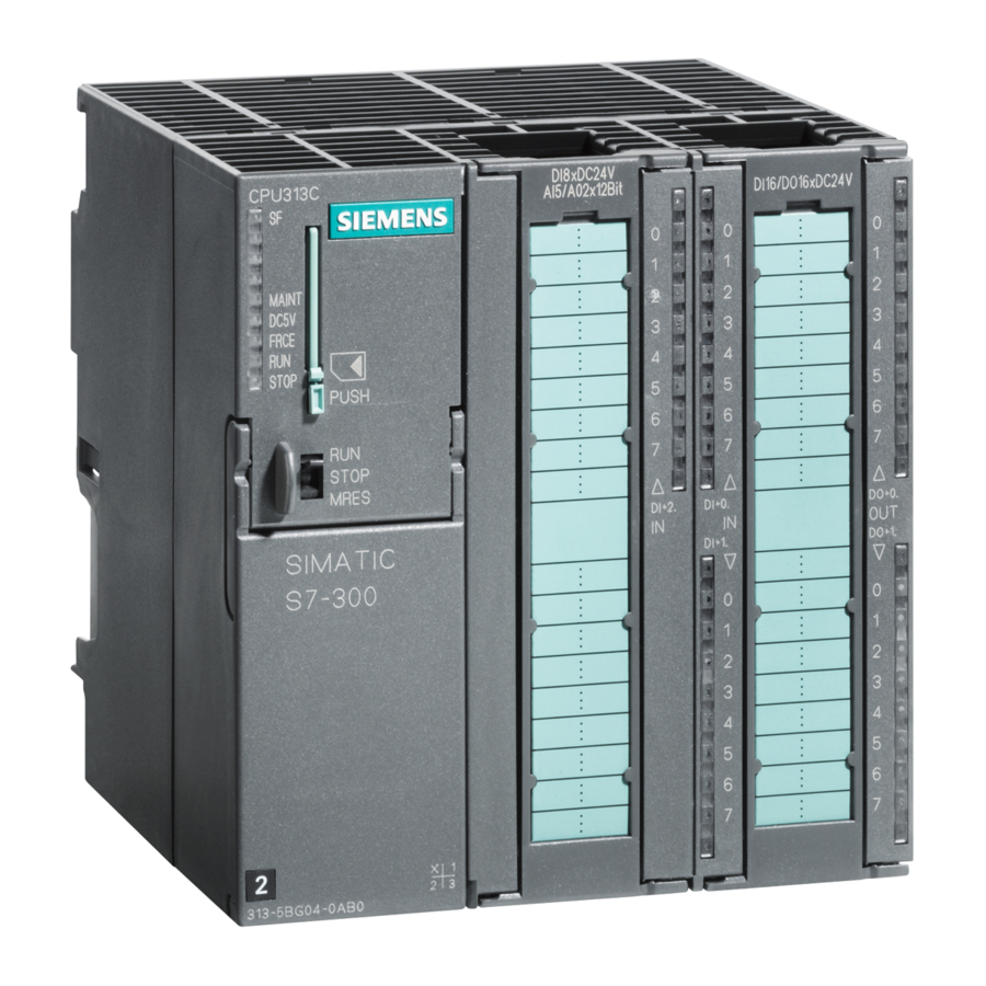
Page 17: Operating And Display Elements
Operating and display elements Operating and display elements: CPU 31xC Operating and display elements of CPU 31xC DC5V FRCE STOP STOP MRES The figures show the following CPU elements Status and error displays Slot for the Micro Memory Card (MMC), incl. the ejector Connections of the integrated I/O. - Page 18 Operating and display elements 2.1 Operating and display elements: CPU 31xC The figure below illustrates the integrated digital and analog I/Os of the CPU with open front covers. DC5V FRCE STOP STOP MRES Figure 2-1 Integrated I/Os of CPU 31xC (CPU 314C-2 PtP, for example) The figure shows the following integrated I/Os Analog I/Os...
- Page 19 Operating and display elements 2.1 Operating and display elements: CPU 31xC Mode selector switch Use the mode selector switch to set the CPU operating mode. Table 2-1 Positions of the mode selector switch Position Meaning Description RUN mode The CPU executes the user program. STOP STOP mode The CPU does not execute a user program.
-
Page 20: Status And Error Indicators: Cpu 31Xc
Operating and display elements 2.1 Operating and display elements: CPU 31xC 2.1.1 Status and Error Indicators: CPU 31xC LED designation Color Meaning Hardware or software error BF (for CPUs with DP Bus error interface only) DC5V green 5-V power for CPU and S7-300 bus is OK FRCE yellow Force job is active... -
Page 21: Operating And Display Elements: Cpu 31X
Operating and display elements 2.2 Operating and display elements: CPU 31x Operating and display elements: CPU 31x 2.2.1 Operating and display elements: CPU 312, 314, 315-2 DP: Operating and display elements DC5V FRCE STOP STOP MRES The figures show the following CPU elements Slot for the Micro Memory Card (MMC), incl. -
Page 22: Table 2-3 Positions Of The Mode Selector Switch
Operating and display elements 2.2 Operating and display elements: CPU 31x Slot for the SIMATIC Micro Memory Card (MMC) A SIMATIC Micro Memory Card (MMC) is used as memory module. You can use MMCs as load memory and as portable storage medium. Note These CPUs do not have an integrated load memory and thus require an MMC for operation. -
Page 23: Operating And Display Elements: Cpu 317-2 Dp
Operating and display elements 2.2 Operating and display elements: CPU 31x 2.2.2 Operating and display elements: CPU 317-2 DP Operating and display elements DC5V FRCE STOP STOP MRES The figures show the following CPU elements Bus error indicator Status and error displays Slot for the Micro Memory Card (MMC), incl. -
Page 24: Table 2-4 Positions Of The Mode Selector Switch
Operating and display elements 2.2 Operating and display elements: CPU 31x Slot for the SIMATIC Micro Memory Card (MMC) A SIMATIC Micro Memory Card (MMC) is used as memory module. You can use MMCs as load memory and as portable storage medium. Note These CPUs do not have an integrated load memory and thus require an MMC for operation. -
Page 25: Operating And Display Elements: Cpu 31X-2 Pn/Dp
Operating and display elements 2.2 Operating and display elements: CPU 31x 2.2.3 Operating and display elements: CPU 31x-2 PN/DP Operating and display elements DC5V FRCE STOP STOP MRES LINK RX / TX MAC-ADD.: X1-X2-X3 X4-X5-X6 The figures show the following CPU elements Bus error indicators Status and error displays Slot for the Micro Memory Card (MMC), incl. - Page 26 Operating and display elements 2.2 Operating and display elements: CPU 31x Slot for the SIMATIC Micro Memory Card (MMC) A SIMATIC Micro Memory Card (MMC) is used as memory module. You can use MMCs as load memory and as portable storage medium. Note These CPUs do not have an integrated load memory and thus require an MMC for operation.
-
Page 27: Status And Error Displays Of The Cpu 31X
Operating and display elements 2.2 Operating and display elements: CPU 31x 2.2.4 Status and error displays of the CPU 31x General status and error displays Table 2-6 General status and error displays of the CPU 31x LED designation Color Meaning Hardware or software error. - Page 28 Operating and display elements 2.2 Operating and display elements: CPU 31x CPU 31xC and CPU 31x, Technical data 2-12 Manual, Edition 08/2004, A5E00105475-05...
-
Page 29: Communication
Communication Interfaces 3.1.1 Multi-Point Interface (MPI) Availability All CPUs described in this manual are equipped with an MPI interface X1. A CPU equipped with an MPI/DP interface is configured and supplied as MPI. To use the DP interface, set DP interface mode in STEP 7. Properties The MPI (Multi-Point Interface) represents the CPU interface for PG/OP connections, or for communication on an MPI subnet. -
Page 30: Profibus Dp
Communication 3.1 Interfaces Devices capable of MPI communication • PG/PC • OP/TP • S7-300 / S7-400 with MPI interface • S7-200 (19.2 kbps only) 3.1.2 PROFIBUS DP Availability CPUs with “DP“ name suffix are equipped at least with a DP X2 interface. The 315-2 PN/DP and 317 CPUs are equipped with an MPI/DP X1 interface. -
Page 31: Profinet (Pn)
Communication 3.1 Interfaces Note (for DP interface in slave mode only) When you disable the Commissioning / Debug mode / Routing check box in the DP interface properties dialog in STEP 7, all user-specific transmission rate settings will be ignored, and the transmission rate of the master is automatically set instead. - Page 32 • For detailed information on Ethernet networks, network configuration and network SIMATIC NET Manual: Twisted Pair and Fiber Optic Networks components refer to the available under article ID 8763736 on the Internet URL http://www.siemens.com/automation/service&support Tutorial: Commissioning Component-Based Automation Systems , article ID 14142554 •...
-
Page 33: Point To Point (Ptp)
Communication 3.1 Interfaces 3.1.4 Point to Point (PtP) Availability CPUs with a “PtP“ name suffix are equipped with a PtP X2 interface. Properties Using the PtP interface of your CPU, you can connect external devices with serial interface. You can operate such a system at transmission rates up to 19.2 kbps in full duplex mode (RS 422), and up to 38.4 kbps in half duplex mode (RS 485). -
Page 34: Communication Services
Communication 3.2 Communication services Communication services 3.2.1 Overview of communication services Selecting the communication service You need to decide on a communication service, based on functionality requirements. Your choice of communication service will have no effect on: • the functionality available, •... -
Page 35: Pg Communication
Communication 3.2 Communication services See also Distribution and availability of S7 connection resources (Page 3-29) Connection resources for routing (Page 3-31) 3.2.2 PG communication Properties PG communication is used to exchange data between engineering stations (PG, PC, for example) and SIMATIC modules which are capable of communication. This service is available for MPI, PROFIBUS and Industrial Ethernet subnets. -
Page 36: S7 Communication
Communication 3.2 Communication services Reference Instruction list • Details on SFCs are found in the , for more details refer to the STEP 7 Online Help System and Standard Functions or to the Reference Manual. Communication with SIMATIC • For further information on communication, refer to the manual. -
Page 37: Global Data Communication (Mpi Only)
Communication 3.2 Communication services 3.2.6 Global data communication (MPI only) Properties Global data communication is used for cyclic exchange of global data via MPI subnets (for example, I, Q, M) between SIMATIC S7 CPUs (data exchange without acknowledgement). One CPU broadcasts its data to all other DP CPUs on the MPI subnet. This function is integrated in the CPU operating system. -
Page 38: Routing
Communication 3.2 Communication services GD resources of the CPUs Table 3-4 GD resources of the CPUs Parameters CPU 31xC, 312, 314 CPU 315-2 DP, 315-2 PN/DP, 317 Number of GD circuits per CPU Max. 4 Max. 8 GD packets transmitted per GD circuit Max. - Page 39 Communication 3.2 Communication services Routing network nodes: MPI - DP Gateways between subnets are routed in a SIMATIC station that is equipped with interfaces to the respective subnets. The figure below shows CPU 1 (DP master) acting as router for subnets 1 and 2.
- Page 40 Communication 3.2 Communication services Routing network nodes: MPI – DP - Ethernet CPU 1 CPU 2 CPU 3 (e.g. 315-2 DP) (317-2 PN/DP) (317-2 PN/DP) MPI/DP (master) (active slave) Subnet 2 (PROFIBUS) Subnet 3 (PROFInet) Subnet 1 (MPI) Number of routed connections The CPUs with DP interface provide a different number of connections for the routing function: Table 3-5...
- Page 41 Communication 3.2 Communication services Requirements • The station modules are "capable of routing" (CPUs or CPs). • The network configuration does not exceed project limits. • The modules have loaded the configuration data containing the latest "knowledge" of the entire network configuration of the project. Reason: All modules participating in the network transition must receive the routing information defining the paths to other subnets.
- Page 42 Communication 3.2 Communication services Routing: Example of a TeleService application The figure below shows the example of an application for remote maintenance of an S7 station using a PG. The connection to other subnets is here established via modem connection. The lower section of the figure shows how to configure this in STEP 7.
-
Page 43: Ptp Communication
• of a basic nature is contained in the Manual. • on the TeleService adapter can be found on the Internet URL: http://www.ad.siemens.de/support. In the Manual Search section, you can enter the search term A5E00078070 to download the documentation. Instruction list STEP 7 Online Help •... -
Page 44: Data Consistency
Communication 3.2 Communication services 3.2.9 Data consistency Properties A data area is considered consistent, if the operating system can read/write access the data area in a continuous block. Data exchanged collectively between the stations should belong together and originate from a single processing cycle, that is, be consistent. If the user program contains a programmed communication function, for example, access to shared data with XSEND/ XRCV, access to that data area can be coordinated by means of the "BUSY"... - Page 45 On the Internet at "www.profibus.com" of PROFIBUS International (previously PROFIBUS User Organization, PUO) you can find numerous articles relating to PROFINET. For further information, refer to the Internet URL "www.siemens.com\profinet\". What is PROFINET IO? Within the framework of PROFINET, PROFINET IO is a communication concept for the implementation of modular, distributed applications.
- Page 46 Communication 3.2 Communication services Extent of PROFINET CBA and PROFINET IO PROFINET IO and CBA represent two different views of automation devices on Industrial Ethernet. Figure 3-1 Extent of PROFINET IO and Component-Based Automation Component-Based Automation organizes the system structure based on the various functions.
-
Page 47: Profinet Io System
Communication 3.2 Communication services 3.2.10.1 PROFINET IO System Extended Functions of PROFINET IO The following graphic shows the new functions of PROFINET IO The graphic displays You can see the connection path in the graphic The connection of company From PCs in your company network, you can access devices at the field level network and field level Example: PC —... -
Page 48: Blocks In Profinet Io
Communication 3.2 Communication services Requirements • CPUs as of Firmware 2.3.0 (for example CPU 315-2 PN/DP) • STEP 7, as of Version 5.3 + Service Pack 1 Reference You will find information on the topic of PROFINET in the following sources: System Description PROFINET •... - Page 49 Communication 3.2 Communication services Comparison of the System and Standard Functions of PROFINET IO and PROFIBUS DP For CPUs with an integrated PROFINET interface, the table below provides you with an overview of: • System and standard functions for SIMATIC that you may need to replace when converting from PROFIBUS DP to PROFINET IO.
-
Page 50: Table 3-7 System And Standard Functions In Profibus Dp That Must Be Implemented With
Communication 3.2 Communication services The following table provides you with an overview of the system and standard functions for SIMATIC, whose functionality must be implemented by other functions when converting from PROFIBUS DP to PROFINET IO. Table 3-7 System and Standard Functions in PROFIBUS DP that must be Implemented with Different Functions in PROFINET IO Blocks PROFINET IO... -
Page 51: System Status Lists (Ssls) In Profinet Io
Communication 3.2 Communication services 3.2.10.3 System status lists (SSLs) in PROFINET IO Chapter Content This chapter explains the following: • Which SSLs are intended for PROFINET • Which SSLs are intended for PROFIBUS DP • Which SSLs are intended for both PROFINET IO and PROFIBUS DP Compatibility of the new SSLs For PROFINET IO, it was necessary to create some new SSLs, among other things, because larger configurations are now possible with PROFINET. -
Page 52: Open Communication Via Industrial Ethernet
Communication 3.2 Communication services Detailed Information System For detailed descriptions of the individual system status lists, refer to the manual Software for S7-300/400 System and Standard Functions 3.2.10.4 Open communication via Industrial Ethernet Requirements • CPU 31x-2 PN/DP with firmware version 2.2.0 or higher: •... - Page 53 Communication 3.2 Communication services Establishing a connection for communication FB 65 "TCON" establishes communication between the CPU and a communication partner. You can establish up to eight connections. The CPU automatically monitors and holds the active connection. Communication partner A must initiate the connection. When the connection of communication partner A is active, it transmits a request to connect to communication partner B.
-
Page 54: Snmp Communication Service
Communication 3.3 S7 connections 3.2.10.5 SNMP communication service Availability The SNMP communication service is available for CPUs with integrated PROFINET interface and Firmware 2.3.0 or higher. Properties SNMP (Simple Network Management Protocol) is a standard protocol for TCP/IP networks. Reference For further information on the SNMP communication service and diagnostics with SNMP, PROFINET System Description. -
Page 55: Assignment Of S7 Connections
Communication 3.3 S7 connections Connection points An S7 connection between modules with communication capability is established between connection points. The S7 connection always has two connection points: The active and passive connection points: • The active connection point is assigned to the module that establishes the S7 connection. •... - Page 56 Communication 3.3 S7 connections Assigning connections in the program In S7 basic communication, and in open Industrial Ethernet communication with TCP/IP, the user program establishes the connection. The CPU operating system initiates the connection. S7 basic communication uses the corresponding S7 connections. The open IE communication does not use any S7 connections.
-
Page 57: Distribution And Availability Of S7 Connection Resources
Communication 3.3 S7 connections 3.3.3 Distribution and availability of S7 connection resources Distribution of connection resources Table 3-10 Distribution of connections Communication service Distribution PG communication In order to avoid allocation of connection resources being dependent only on the chronological sequence in which various communication services are OP communication requested, connection resources can be reserved for these services. -
Page 58: Table 3-11 Availability Of Connection Resources
Communication 3.3 S7 connections Availability of connection resources Table 3-11 Availability of connection resources Total number Reserved for Free connection S7 connections OP communication S7 basic resources communication communication 312C 1 to 5, default 1 1 to 5, default 1 0 to 2, default 2 Displays all non- reserved S7... -
Page 59: Connection Resources For Routing
Communication 3.3 S7 connections 3.3.4 Connection resources for routing Number of connection resources for routing The CPUs with DP interface provide a different number of connection resources for the routing function: Table 3-12 Number of routing connection resources (for DP/PN CPUs) As of firmware version Number of connections for routing 31xC, CPU 31x... -
Page 60: Dpv1
Communication 3.4 DPV1 DPV1 New automation and process engineering tasks require the range of functions performed by the existing DP protocol to be extended. In addition to cyclical communication functions, acyclical access to non-S7 field devices is another important requirement of our customers, and was implemented in the standard EN 50170. -
Page 61: Table 3-13 Interrupt Blocks With Dpv1 Functionality
Communication 3.4 DPV1 Interrupt blocks with DPV1 functionality Table 3-13 Interrupt blocks with DPV1 functionality Functionality OB 40 Process interrupt OB 55 Status interrupt OB 56 Update interrupt OB 57 Vendor-specific interrupt OB 82 Diagnostic interrupt Note You can now also use organizational blocks OB40 and OB82 for DPV1 interrupts. System blocks with DPV1 functionality Table 3-14 System function blocks with DPV1 functionality... - Page 62 Communication 3.4 DPV1 CPU 31xC and CPU 31x, Technical data 3-34 Manual, Edition 08/2004, A5E00105475-05...
-
Page 63: Memory Concept
Memory concept Memory areas and retentivity 4.1.1 CPU memory areas The three memory areas of your CPU: Memory of the CPU Loading memory (located on the MMC) System memory Working memory Load memory The load memory is located on a Micro Memory Card (MMC). The size of the load memory corresponds exactly to the size of the MMC. -
Page 64: Retentivity Of The Load Memory, System Memory And Ram
Memory concept 4.1 Memory areas and retentivity System memory The RAM system memory is integrated in the CPU and cannot be expanded. It contains • the address areas for address area memory bits, timers and counters • the process image of the I/Os •... -
Page 65: Retentivity Of Memory Objects
Memory concept 4.1 Memory areas and retentivity Retentive data in RAM Therefore, the contents of retentive DBs are always retentive at restart and POWER ON/OFF. CPUs V2.1.0 or higher also support volatile DBs (the volatile DBs are initialized at restart of POWER OFF-ON with their initial values from load memory.) See also Properties of the Micro Memory Card (MMC) (Page 4-9) - Page 66 Memory concept 4.1 Memory areas and retentivity Retentive behavior of a DB for CPUs with firmware >= V2.1.0 For these CPUs you can specify in STEP 7 (beginning with version 5.2 + SP 1), or at SFC 82 CREA_DBL (parameter ATTRIB -> NON_RETAIN bit), whether a DB at POWER ON/OFF or RUN-STOP •...
-
Page 67: Address Areas Of System Memory
Memory concept 4.1 Memory areas and retentivity 4.1.4 Address areas of system memory System memory of the S7 CPUS is organized in address areas (refer to the table below). In a corresponding operation of your user program, you address data directly in the relevant address area. - Page 68 Memory concept 4.1 Memory areas and retentivity Process image update The operating system updates the process image periodically. The figure below shows the sequence of this operation within a cycle. Startup Startup program Processing the user program (OB 1) and all programs called inside of it. Reading the inputs from the modules and refreshing the data in the process image of the inputs.
- Page 69 Memory concept 4.1 Memory areas and retentivity Configurable process image with CPU317 (FW V2.3.0 or higher) IN STEP 7, you can define a user-specific size of the I/O process images between 0 to 2048 for a CPU317, FW V2.3.0 or higher. Note the information below: Note Currently, the dynamic setting of the process image only affects its update at the scan cycle...
- Page 70 Memory concept 4.1 Memory areas and retentivity Local data Local data store: • the temporary variables of code blocks • the start information of the OBs • transfer parameters • intermediate results Temporary Variables When you create blocks, you can declare temporary variables (TEMP) which are only available during block execution and then overwritten again.
-
Page 71: Properties Of The Micro Memory Card (Mmc)
Memory concept 4.1 Memory areas and retentivity 4.1.5 Properties of the Micro Memory Card (MMC) The MMC as memory module for the CPU The memory module used on your CPU is a SIMATIC Micro Memory Card (MMC.) You can use MMCs as load memory or as a portable storage medium. Note The CPU requires the MMC for operation. - Page 72 Memory concept 4.1 Memory areas and retentivity MMC copy protection Your MMC has an internal serial number that provides copy protection at user level. You can read this serial number from the SSL partial list 011C index 8 using SFC 51 "RDSYSST." You can then program a STOP command, for example, in a copy-protected block if the expected and actual serial numbers of your MCC do not tally.
-
Page 73: Memory Functions
Memory concept 4.2 Memory functions Memory functions 4.2.1 General: Memory functions Memory functions Memory functions are used to generate, modify or delete entire user programs or specific blocks. You can also ensure that your project data are retained by archiving these. If there is... -
Page 74: Handling With Modules
Memory concept 4.2 Memory functions Note This function is only permitted when the CPU is in STOP mode. Load memory is cleared if the load operation could not be completed due to power loss or illegal block data. 4.2.3 Handling with modules 4.2.3.1 Download of new blocks or delta downloads There are two ways to download additional user blocks or download deltas:... -
Page 75: Deleting Blocks
Memory concept 4.2 Memory functions 4.2.3.3 Deleting blocks Deleting blocks When you delete a block, it is deleted from load memory. In STEP 7, you can also delete blocks with the user program (DBs also with SFC 23 "DEL_DB"). RAM used by this block is released. - Page 76 Memory concept 4.2 Memory functions Restart (warm start) • All retentive DBs retain their actual value (non-retentive DBs are also supported by CPUs with Firmware >= V2.1.0. Non-retentive DBs receive their initial values). • The values of all retentive M, C, T are retained. •...
-
Page 77: Recipes
Memory concept 4.2 Memory functions 4.2.5 Recipes Introduction A recipe represents a collection of user data. You can implement a simple recipe concept using static DBs. In this case, the recipes should have the same structure (length). One DB should exist per recipe. Processing sequence Recipe is written to load memory: •... - Page 78 Memory concept 4.2 Memory functions Note As a precaution against loss of data, always make sure that you do not exceed the maximum number of delete/write operations. Also refer to the SIMATIC Micro Memory Card (MMC) section in the "Structure and Communication Connections of a CPU" chapter.
-
Page 79: Measured Value Log Files
Memory concept 4.2 Memory functions 4.2.6 Measured value log files Introduction Measured values are generated when the CPU executes the user program. These values are to be logged and analyzed. Processing sequence Acquisition of measured values: • The CPU writes all measured values to a DB (for alternating backup mode in several DBs) which is located in RAM. - Page 80 Memory concept 4.2 Memory functions The data written to load memory are portable and retentive on CPU memory reset. Evaluation of measured values: • Measured value DBs saved to load memory can be uploaded and evaluated by other communication partners (PG, PC, for example). Note The active system functions SFC 82 to 84 (current access to the MMC) have a distinct influence on PG functions (block status, variable status, load block, upload, open, for...
-
Page 81: Backup Of Project Data To A Micro Memory Card (Mmc)
Memory concept 4.2 Memory functions 4.2.7 Backup of project data to a Micro Memory Card (MMC) Function principle Using the Save project to Memory Card and Fetch project from Memory Card functions, you can save all project data to a SIMATIC Micro Memory Card, and retrieve these at a later time. - Page 82 Memory concept 4.2 Memory functions CPU 31xC and CPU 31x, Technical data 4-20 Manual, Edition 08/2004, A5E00105475-05...
-
Page 83: Cycle And Reaction Times
Cycle and reaction times Overview Overview This section contains detailed information about the following topics: • Cycle time • Reaction time • Interrupt response time • Sample calculations Reference: Cycle time You can view the cycle time of your user program on the PG. For further information, refer to STEP 7 Online Help Configuring Hardware and Connections in STEP 7 , or to the... -
Page 84: Cycle Time
Cycle and reaction times 5.2 Cycle time Cycle time 5.2.1 Overview Introduction This section explains what we mean by the term "cycle time", what it consists of, and how you can calculate it. Meaning of the term cycle time The cycle time represents the time that an operating system needs to execute a program, that is, one OB 1 cycle, including all program sections and system activities interrupting this cycle. - Page 85 Cycle and reaction times 5.2 Cycle time Sequence of cyclic program processing The table and figure below show the phases in cyclic program processing. Table 5-1 Cyclic program processing Step Sequence The operating system initiates cycle time monitoring. The CPU copies the values of the process image of outputs to the output modules. The CPU reads the status at the inputs of the input modules and then updates the process image of inputs.
- Page 86 Cycle and reaction times 5.2 Cycle time Extending the cycle time Always make allowances for the extension of the cycle time of a user program due to: • Time-based interrupt processing • Process interrupt processing • Diagnostics and error processing •...
-
Page 87: Calculating The Cycle Time
Cycle and reaction times 5.2 Cycle time 5.2.2 Calculating the cycle time Introduction The cycle time is derived from the sum of the following influencing factors. Process image update The table below shows the time a CPU requires to update the process image (process image transfer time). - Page 88 Cycle and reaction times 5.2 Cycle time Table 5-4 CPU 31x: Data for calculating the process image (PI) transfer time Const. Portions CPU 312 CPU 314 CPU 315 CPU 317 Base load 150 μs 100 μs 100 μs 50 μs per byte in module 37 μs 35 μs...
- Page 89 Cycle and reaction times 5.2 Cycle time Operating system processing time at the scan cycle checkpoint The table below shows the operating system processing time at the scan cycle checkpoint of the CPUs. These times are calculated without taking into consideration times for: •...
-
Page 90: Different Cycle Times
Cycle and reaction times 5.2 Cycle time Extension of the cycle time due to error Table 5-8 Cycle time extension as a result of errors Type of error Programming errors I/O access errors 312C 600 μs 600 μs 313C 400 μs 400 μs 313C2 400 μs... -
Page 91: Communication Load
Cycle and reaction times 5.2 Cycle time Maximum cycle time STEP 7 you can modify the default maximum cycle time. OB80 is called on when this time expires. In this block you can specify the CPUs response to this timeout error. The CPU switches to STOP mode if OB80 does not exist in its memory. - Page 92 Cycle and reaction times 5.2 Cycle time Physical cycle time depending on communication load The figure below describes the non-linear dependency of the physical cycle time on communication load. In our sample we have chosen a cycle time of 10 ms. Cycle time 30 ms The communication load can...
-
Page 93: Cycle Time Extension As A Result Of Testing And Commissioning Functions
Cycle and reaction times 5.2 Cycle time 5.2.5 Cycle time extension as a result of testing and commissioning functions Runtimes The runtimes of the testing and commissioning functions are operating system runtimes, so they are the same for every CPU. Initially, there is no difference between process mode and testing mode. - Page 94 Cycle and reaction times 5.2 Cycle time Note The use of CBA with cyclical PROFINET interconnections requires the use of switches to maintain the performance data. 100-Mbit full-duplex operation is mandatory with cyclical PROFINET interconnections. The following graphic shows the configuration that was used for the measurements. HMI/OPC Industrial Ethernet Number of observed...
- Page 95 Cycle and reaction times 5.2 Cycle time Additional marginal conditions The maximum cycle load through communication in the measurement is 20 %. The lower graphic shows that the OB1 cycle is influenced by increasing the cyclical PROFINET interconnections to remote partners at PROFINET: Dependency of the OB1 cycle on the number of interconnections Cycle time in ms OB1 cycle with 32 remote...
-
Page 96: Response Time
Cycle and reaction times 5.3 Response time Response time 5.3.1 Overview Definition of response time The response time is the time between the detection of an input signal and the change of a linked output signal. Fluctuation width The physical response time lies between the shortest and the longest response time. You must always reckon with the longest response time when configuring your system. - Page 97 Cycle and reaction times 5.3 Response time DP cycle times in the PROFIBUS DP network If you have configured your PROFIBUS DP master system in STEP 7, STEP 7 calculates the typical DP cycle time to be expected. You can then view the DP cycle time of your configuration on the PG.
-
Page 98: Shortest Response Time
Cycle and reaction times 5.3 Response time 5.3.2 Shortest response time Conditions for the shortest response time The figure below shows the conditions under which the shortest response time is reached. CCP (OS) Delay of inputs Immediately before reading in the PII, the status of the monitored input changes. -
Page 99: Longest Response Time
Cycle and reaction times 5.3 Response time 5.3.3 Longest response time Conditions for the longest response time The figure below shows the conditions under which the longest response time is reached. CCP (OS) Delay of inputs + 2 x DP cycle time at PROFIBUS DP While reading in the PII, the status of the monitored input changes. -
Page 100: Reducing The Response Time With Direct I/O Access
Cycle and reaction times 5.3 Response time Calculation The (longest) response time is the sum of: Table 5-11 Formula: Longest response time 2 x process image transfer time for the inputs 2 x process image transfer time for the outputs 2 x program processing time 2 ×... -
Page 101: Calculating Method For Calculating The Cycle/Response Time
Cycle and reaction times 5.4 Calculating method for calculating the cycle/response time Calculating method for calculating the cycle/response time Introduction This section gives you an overview of how to calculate the cycle/response time. Cycle time Instruction list 1. Determine the user program runtime with the help of the Extension of user 2. - Page 102 Cycle and reaction times 5.4 Calculating method for calculating the cycle/response time Response time Table 5-12 Calculating the response time Shortest response time Longest response time Multiply the physical cycle time by factor 2. Now add I/O delay. Now add the I/O delay plus the DP cycle times on PROFIBUS-DP or the PROFINET IO update times.
-
Page 103: Interrupt Response Time
Cycle and reaction times 5.5 Interrupt response time Interrupt response time 5.5.1 Overview Definition of interrupt response time The interrupt response time is the time that expires between the first occurrence of an interrupt signal and the call of the first interrupt OB instruction. Generally valid: Higher- priority interrupts take priority. - Page 104 Cycle and reaction times 5.5 Interrupt response time Calculation The formula below show how you can calculate the minimum and maximum interrupt response times. Table 5-14 Process/diagnostic interrupt response times Calculation of the minimum and maximum interrupt reaction time Minimum interrupt reaction time of the CPU Maximum interrupt reaction time of the CPU + Minimum interrupt reaction time of the + Maximum interrupt reaction time of the signal...
-
Page 105: Reproducibility Of Delay Interrupts And Watchdog Interrupts
Cycle and reaction times 5.5 Interrupt response time Process interrupt processing Process interrupt processing begins after process interrupt OB40 is called. Higher-priority interrupts stop process interrupt processing. Direct I/O access is executed during runtime of the instruction. After process interrupt processing has terminated, cyclic program execution continues or further interrupt OBs of equal or lower priority are called and processed. -
Page 106: Sample Calculations
Cycle and reaction times 5.6 Sample calculations Sample calculations 5.6.1 Example of cycle time calculation Installation You have configured an S7300 and equipped it with following modules in rack "0": • a CPU 314C-2 • 2 digital input modules SM 321; DI 32 x 24 VDC (4 bytes each in the PI) •... -
Page 107: Sample Of Response Time Calculation
Cycle and reaction times 5.6 Sample calculations Calculating the longest response time Longest response time: 6.8 ms x 2 = 13.6 ms. • I/O delay can be neglected. • Neither PROFIBUS DP, nor PROFINET IO are being used, so you do not have to make allowances for any DP cycle times on PROFIBUS DP or for PROFINET IO update times. -
Page 108: Communication
Cycle and reaction times 5.6 Sample calculations Calculating the physical cycle time Under consideration of communication load: 12.5 ms * 100 / (100-40) = 20.8 ms. Thus, under consideration of time-sharing factors, the actual cycle time is 21 ms. Calculation of the longest response time •... -
Page 109: Example Of Interrupt Response Time Calculation
Cycle and reaction times 5.6 Sample calculations 5.6.3 Example of interrupt response time calculation Installation You have assembled an S7-300, consisting of one CPU 314C-2 and four digital modules in the CPU rack. One of the digital input modules is an SM 321; DI 16 x 24 VDC; with process/diagnostic interrupt function. -
Page 110: A5E00105475
Cycle and reaction times 5.6 Sample calculations CPU 31xC and CPU 31x, Technical data 5-28 Manual, Edition 08/2004, A5E00105475-05... -
Page 111: Technical Data Of Cpu 31Xc
Technical data of CPU 31xC General technical data 6.1.1 Dimensions of CPU 31xC Each CPU features the same height and depth, only the width dimensions differ. • Height: 125 mm • Depth: 115 mm, or 180 mm with opened front cover. Width of CPU Width CPU 312C... -
Page 112: Technical Data Of The Micro Memory Card (Mmc)
Technical data of CPU 31xC 6.1 General technical data 6.1.2 Technical data of the Micro Memory Card (MMC) Plug-in SIMATIC Micro Memory Cards The following memory modules are available: Table 6-1 Available MMCs Type Order number Required for a firmware update via MMC MMC 64k 6ES7 953-8LFxx-0AA0 –... -
Page 113: Cpu 312C
Technical data of CPU 31xC 6.2 CPU 312C CPU 312C Technical data Table 6-3 Technical data of CPU 312C Technical data CPU and version Order number 6ES7 312-5BD01-0AB0 Hardware version • Firmware version • V2.0 Associated programming package • STEP 7 as of V 5.2 + SP 1 (please use previous CPU for STEP 7 V 5.1 + SP 3 or later) Memory... - Page 114 Technical data of CPU 31xC 6.2 CPU 312C Technical data IEC Timers Type • Number • unlimited (limited only by RAM size) Data areas and their retentivity Flag bits 128 bytes Retentive memory • Configurable Default retentivity • MB0 to MB15 Clock flag bits 8 (1 byte per flag bit) Data blocks...
- Page 115 Technical data of CPU 31xC 6.2 CPU 312C Technical data Assembly Racks Max. 1 Modules per rack Max. 8 Number of DP masters Integrated • None Via CP • Max. 1 Number of function modules and communication processors you can operate •...
- Page 116 Technical data of CPU 31xC 6.2 CPU 312C Technical data Block status Single step Breakpoints Diagnostic buffer Number of entries (not configurable) • Max. 100 Communication functions PG/OP communication Global data communication Number of GD circuits • Number of GD packets •...
- Page 117 Technical data of CPU 31xC 6.2 CPU 312C Technical data Functionality • PROFIBUS DP • Point-to-point communication • Services PG/OP communication • Routing • Global data communication • S7 basic communication • S7 communication • As server – As client –...
-
Page 118: Cpu 313C
Technical data of CPU 31xC 6.3 CPU 313C Technical data 0.7 A External fusing of power supply lines LS switch Type C min. 2 A, (recommended) LS switch Type B min. 4 A Power loss Typically 6 W Reference Specifications of the integrated I/O In Chapter you can find Digital inputs of CPUs 31xC... - Page 119 Technical data of CPU 31xC 6.3 CPU 313C Technical data Timers/counters and their retentivity S7 counters Retentive memory • Configurable Default • from C0 to C7 Counting range • 0 to 999 IEC Counters Type • Number • unlimited (limited only by RAM size) S7 timers Retentive memory •...
- Page 120 Technical data of CPU 31xC 6.3 CPU 313C Technical data Address areas (I/O) Total I/O address area max. 1024 bytes/1024 bytes (can be freely addressed) I/O process image 128 bytes/128 bytes Digital channels Max. 1016 of those local • Max. 992 Integrated channels •...
- Page 121 Technical data of CPU 31xC 6.3 CPU 313C Technical data Process diagnostics messages Simultaneously enabled interrupt S blocks • Max. 20 Testing and commissioning functions Status/control variables Variables • Inputs, outputs, memory bits, DBs, timers, counters Number of variables • Max.
- Page 122 Technical data of CPU 31xC 6.3 CPU 313C Technical data can be used for PG communication • Max. 7 Reserved (default) – Configurable – from 1 to 7 OP communication • Max. 7 Reserved (default) – Configurable – from 1 to 7 S7 basic communication •...
- Page 123 Technical data of CPU 31xC 6.3 CPU 313C Technical data Integrated I/O Default addresses of the integrated • Digital inputs – 124.0 to 126.7 Digital outputs – 124.0 to 125.7 Analog inputs – 752 to 761 Analog outputs – 752 to 755 Integrated functions Technological Counters...
-
Page 124: Cpu 313C-2 Ptp And Cpu 313C-2 Dp
Technical data of CPU 31xC 6.4 CPU 313C-2 PtP and CPU 313C-2 DP CPU 313C-2 PtP and CPU 313C-2 DP Technical data Table 6-5 Technical data for CPU 313C-2 PtP/ CPU 313C-2 DP Technical data CPU 313C-2 PtP CPU 313C-2 DP CPU and version CPU 313C-2 PtP CPU 313C-2 DP... - Page 125 Technical data of CPU 31xC 6.4 CPU 313C-2 PtP and CPU 313C-2 DP Technical data CPU 313C-2 PtP CPU 313C-2 DP Data areas and their retentivity CPU 313C-2 PtP CPU 313C-2 DP Flag bits 256 bytes Retentive memory Configurable • Default retentivity •...
- Page 126 Technical data of CPU 31xC 6.4 CPU 313C-2 PtP and CPU 313C-2 DP Technical data CPU 313C-2 PtP CPU 313C-2 DP Number of function modules and communication processors you can operate • Max. 8 CP (PtP) • Max. 8 CP (LAN) •...
- Page 127 Technical data of CPU 31xC 6.4 CPU 313C-2 PtP and CPU 313C-2 DP Technical data CPU 313C-2 PtP CPU 313C-2 DP Communication functions CPU 313C-2 PtP CPU 313C-2 DP PG/OP communication Global data communication Number of GD circuits • Number of GD packets •...
- Page 128 Technical data of CPU 31xC 6.4 CPU 313C-2 PtP and CPU 313C-2 DP Technical data CPU 313C-2 PtP CPU 313C-2 DP Services PG/OP communication • Routing • Global data communication • S7 basic communication • S7 communication • • As server •...
- Page 129 Max. 32, with max. 32 bytes each DPV1 • – GSD file – The latest GSD file is available at: http://www.ad.siemens.de/support in the Product Support area Point-to-point communication Transmission rates • 38.4 kbps half duplex – 19.2 kbps full duplex Cable length •...
- Page 130 Technical data of CPU 31xC 6.4 CPU 313C-2 PtP and CPU 313C-2 DP Technical data CPU 313C-2 PtP CPU 313C-2 DP Integrated functions Technological Functions Counters 3 channels (see the Manual Technological Functions Frequency counters 3 channels, max. 30 kHz (see the Manual Pulse outputs 3 channels for pulse width modulation, max.
-
Page 131: Cpu 314C-2 Ptp And Cpu 314C-2 Dp
Technical data of CPU 31xC 6.5 CPU 314C-2 PtP and CPU 314C-2 DP CPU 314C-2 PtP and CPU 314C-2 DP Technical data Table 6-6 Technical data of CPU 314C-2 PtP and CPU 314C-2 DP Technical data CPU 314C-2 PtP CPU 314C-2 DP CPU and version CPU 314C-2 PtP CPU 314C-2 DP... - Page 132 Technical data of CPU 31xC 6.5 CPU 314C-2 PtP and CPU 314C-2 DP Technical data CPU 314C-2 PtP CPU 314C-2 DP Data areas and their retentivity CPU 314C-2 PtP CPU 314C-2 DP Flag bits 256 bytes Retentive memory Configurable • Default retentivity •...
- Page 133 Technical data of CPU 31xC 6.5 CPU 314C-2 PtP and CPU 314C-2 DP Technical data CPU 314C-2 PtP CPU 314C-2 DP Number of function modules and communication processors you can operate • Max. 8 CP (PtP) • Max. 8 CP (LAN) •...
- Page 134 Technical data of CPU 31xC 6.5 CPU 314C-2 PtP and CPU 314C-2 DP Technical data CPU 314C-2 PtP CPU 314C-2 DP Communication functions CPU 314C-2 PtP CPU 314C-2 DP PG/OP communication Global data communication Number of GD circuits • Number of GD packets •...
- Page 135 Technical data of CPU 31xC 6.5 CPU 314C-2 PtP and CPU 314C-2 DP Technical data CPU 314C-2 PtP CPU 314C-2 DP Number of connections Services PG/OP communication • Routing • Global data communication • S7 basic communication • S7 communication •...
- Page 136 Max. 32, with max. 32 bytes each DPV1 • – GSD file – The latest GSD file is available at: http://www.ad.siemens.de/support in the Product Support area Point-to-point communication Transmission rates • 38.4 kbps half duplex – 19.2 kbps full duplex Cable length •...
- Page 137 Technical data of CPU 31xC 6.5 CPU 314C-2 PtP and CPU 314C-2 DP Technical data CPU 314C-2 PtP CPU 314C-2 DP Integrated functions Technological Functions Counters 4 channels (see the Manual Technological Functions Frequency counters 4 channels, max. 60 kHz (see the Manual Pulse outputs 4 channels for pulse width modulation, max.
-
Page 138: Technical Data Of The Integrated I/O
Technical data of CPU 31xC 6.6 Technical data of the integrated I/O Technical data of the integrated I/O 6.6.1 Arrangement and usage of integrated I/Os Introduction Integrated I/Os of CPUs 31xC can be used for technological functions or as standard I/O. The figures below illustrate possible usage of I/Os integrated in the CPUs. - Page 139 Technical data of CPU 31xC 6.6 Technical data of the integrated I/O Block diagram of the integrated digital I/O CPU 31xC and CPU 31x, Technical data 6-29 Manual, Edition 08/2004, A5E00105475-05...
- Page 140 Technical data of CPU 31xC 6.6 Technical data of the integrated I/O CPU 313C, CPU 313C-2 DP/PtP, CPU 314C-2 DP/PtP: DI/DO (connectors X11 and X12) X11 of CPU 313C-2 PtP/DP X12 of CPU 314C-2 PtP/DP Interrupt Posi- Standard Count Count Standard Positioning input...
- Page 141 Technical data of CPU 31xC 6.6 Technical data of the integrated I/O Block diagram of integrated digital I/O of CPUs 313C/313C-2/314C-2 CPU 31xC and CPU 31x, Technical data 6-31 Manual, Edition 08/2004, A5E00105475-05...
- Page 142 Technical data of CPU 31xC 6.6 Technical data of the integrated I/O CPU 313C/314C-2: Pin-out of the integrated AI/AO and DI (connector X11) Interrupt input Standard DI Standard Positioning DI+2.0 PEWx+0 DI+2.1 AI (Ch0) DI+2.2 DI+2.3 DI+2.4 PEWx+2 AI (Ch1) DI+2.5 DI+2.6 PEWx+4...
- Page 143 Technical data of CPU 31xC 6.6 Technical data of the integrated I/O Simultaneous usage of technological functions and standard I/O Technological functions and standard I/O can be used simultaneously with appropriate hardware. For example, you can use all digital inputs not used for counting functions as standard DI.
-
Page 144: Analog I/O
Technical data of CPU 31xC 6.6 Technical data of the integrated I/O 6.6.2 Analog I/O Wiring of the current/voltage inputs The figure below shows the wiring diagram of the current/voltage inputs operated with 2-/4-wire measuring transducers. : Pin 2 to 4 2-wire : Pin 5 to 7 signal converter... - Page 145 Technical data of CPU 31xC 6.6 Technical data of the integrated I/O Measurement principle 31xC CPUs use the measurement principle of actual value encoding. Here, they operate with a sampling rate of 1 kHz. That is, a new value is available at the peripheral input word register once every millisecond.
- Page 146 Technical data of CPU 31xC 6.6 Technical data of the integrated I/O Input filters (software filter) The current / voltage inputs have a software filter for the input signals which can be programmed with STEP 7. It filters the configured interference frequency (50/60 Hz) and multiples thereof.
- Page 147 Technical data of CPU 31xC 6.6 Technical data of the integrated I/O In the two graphics below we illustrate how the 50 Hz and 60 Hz interference suppression work Example of a 50-Hz parasitic frequency suppression (integration time corresponds to 20 ms) 1.05 ms 1.05 ms 1.05 ms...
- Page 148 Technical data of CPU 31xC 6.6 Technical data of the integrated I/O Example of a 60-Hz parasitic frequency suppression (integration time corresponds to 16.7 ms) 1.05 ms 1.05 ms 1.05 ms 1.05 ms 1.05 ms . . . Cycle 1 Value Value Value...
-
Page 149: Configuration
Technical data of CPU 31xC 6.6 Technical data of the integrated I/O 6.6.3 Configuration Introduction You configure the integrated I/O of CPU 31xC with STEP 7. Always make these settings when the CPU is in STOP. The generated parameters are downloaded from the PG to the S7-300 and written to CPU memory . - Page 150 Technical data of CPU 31xC 6.6 Technical data of the integrated I/O Byte 0 Byte 0 0 Bit-Nr. Interrupt input DI +0.0 Interrupt input DI +0.1 Interrupt input DI +0.7 Byte 1 0 Bit-Nr. Interrupt input DI +1.0 Interrupt input DI +1.1 Interrupt input DI +1.7 0 Bit-Nr.
- Page 151 Technical data of CPU 31xC 6.6 Technical data of the integrated I/O Parameters of standard DO There are no parameters for standard digital outputs. Parameters of standard AI The table below gives you an overview of the parameters for standard analog inputs. Table 6-9 Parameters of standard AI Parameters...
- Page 152 Technical data of CPU 31xC 6.6 Technical data of the integrated I/O Parameters of standard AO The table below gives you an overview of standard analog output parameters (see also Module Data Chapter 4.3 in the Reference Manual). Table 6-10 Parameters of standard AO Parameters Value range...
- Page 153 Technical data of CPU 31xC 6.6 Technical data of the integrated I/O reserved Unit of measure Celsius Fahrenheit Kelvin Default setting: reserved Parasitic frequency suppression integration time of channel AI 0 Parasitic frequency suppression integration time of channel AI 1 Parasitic frequency suppression integration time of channel AI 2 Parasitic frequency suppression integration time of channel AI 3 Default setting:...
- Page 154 Technical data of CPU 31xC 6.6 Technical data of the integrated I/O Output range of channel AO 0 (setting see byte 12) Output range of channel AO 0 (setting see byte 12) Output range of channel AO 1 deactivated 0 … 20 mA 4 …...
-
Page 155: Interrupts
Technical data of CPU 31xC 6.6 Technical data of the integrated I/O 6.6.4 Interrupts Interrupt inputs All digital inputs of the on-board I/O of CPUs 31xC can be used as interrupt inputs. You can specify interrupt behavior for each individual input in your parameter declaration. Options are: •... -
Page 156: Diagnostics
Technical data of CPU 31xC 6.6 Technical data of the integrated I/O 31 30 29 28 27 26 25 24 … 16 15 … 8 7 6 5 4 3 2 1 Bit no. reserved PRAL from E124.0 PRAL from E124.7 PRAL from E125.0 PRAL from E125.7 PRAL from E126.0... -
Page 157: Table 6-12 Technical Data Of Digital Inputs
Technical data of CPU 31xC 6.6 Technical data of the integrated I/O Technical data Table 6-12 Technical data of digital inputs Technical data CPU 312C CPU 313C CPU 313C-2 CPU 314C-2 Module-specific data CPU 312C CPU 313C CPU 313C-2 CPU 314C-2 Number of inputs Number of these inputs which can be used •... -
Page 158: Digital Outputs
Technical data of CPU 31xC 6.6 Technical data of the integrated I/O Technical data CPU 312C CPU 313C CPU 313C-2 CPU 314C-2 Data for the selection of an encoder for CPU 312C CPU 313C CPU 313C-2 CPU 314C-2 standard DI Input voltage Rated value •... -
Page 159: Table 6-13 Technical Data Of Digital Outputs
Technical data of CPU 31xC 6.6 Technical data of the integrated I/O Technical data Table 6-13 Technical data of digital outputs Technical data CPU 312C CPU 313C CPU 313C-2 CPU 314C-2 Module-specific data CPU 312C CPU 313C CPU 313C-2 CPU 314C-2 Number of outputs Of those are fast outputs •... - Page 160 Technical data of CPU 31xC 6.6 Technical data of the integrated I/O Technical data CPU 312C CPU 313C CPU 313C-2 CPU 314C-2 Data for the selection of an actuator for CPU 312C CPU 313C CPU 313C-2 CPU 314C-2 standard DI Output voltage For signal "1"...
-
Page 161: Analog Inputs
Technical data of CPU 31xC 6.6 Technical data of the integrated I/O 6.6.8 Analog inputs Introduction This chapter contains the specifications for analog outputs of CPUs 31xC. The table includes the following CPUs: • CPU 313C • CPU 314C-2 DP •... - Page 162 Technical data of CPU 31xC 6.6 Technical data of the integrated I/O Technical data Time constant of the input filter 0,38 ms Basic processing time 1 ms Interference suppression, error limits Interference voltage suppression for f = nx (f1 ± 1 %), (f1 = interference frequency), n = 1, 2 Commonmode interference (U <...
-
Page 163: Analog Outputs
Technical data of CPU 31xC 6.6 Technical data of the integrated I/O Technical data Connection of signal generators For voltage measurement • Possible For current measurement • as 2-wire measuring transducer – Possible, with external power supply as 4-wire measuring transducer –... - Page 164 Technical data of CPU 31xC 6.6 Technical data of the integrated I/O Technical data Permitted potential difference between M and M • 75 VDC / 60 VAC internal Insulation test voltage 600 VDC Analog value generation Resolution (including overdrive) 11 bits + signed bit Conversion time (per channel) 1 ms Settling time...
- Page 165 Technical data of CPU 31xC 6.6 Technical data of the integrated I/O Technical data Voltage output Short-circuit protection • Short-circuit current • Typically 55 mA Current output No-load voltage • Typically 17 V Destruction limit for externally applied voltages/currents Voltage measured between the outputs and M •...
- Page 166 Technical data of CPU 31xC 6.6 Technical data of the integrated I/O CPU 31xC and CPU 31x, Technical data 6-56 Manual, Edition 08/2004, A5E00105475-05...
-
Page 167: Technical Data Of Cpu 31X
Technical data of CPU 31x General technical data 7.1.1 Dimensions of CPU 31x Each CPU features the same height and depth, only the width dimensions differ. • Height: 125 mm • Depth: 115 mm, or 180 mm with opened front cover. Figure 7-1 Dimensions of CPU 31x Width of CPU... -
Page 168: Technical Data Of The Micro Memory Card (Mmc)
Technical data of CPU 31x 7.1 General technical data 7.1.2 Technical data of the Micro Memory Card (MMC) Plug-in SIMATIC Micro Memory Cards The following memory modules are available: Table 7-1 Available MMCs Type Order number Required for a firmware update via MMC MMC 64k 6ES7 953-8LFxx-0AA0 –... -
Page 169: Cpu 312
Technical data of CPU 31x 7.2 CPU 312 CPU 312 Technical data Table 7-3 Technical data for the CPU 312 Technical data CPU and version Order number 6ES7312-1AD10-0AB0 Hardware version • Firmware version • V2.0.0 Associated programming package • STEP 7 as of V 5.1 + SP 4 Memory Integrated •... - Page 170 Technical data of CPU 31x 7.2 CPU 312 Technical data Data areas and their retentivity Flag bits 128 bytes Retentive memory • Default retentivity • MB0 to MB15 Clock flag bits 8 (1 byte per flag bit) Data blocks (DB 1 to DB 511) Length •...
- Page 171 Technical data of CPU 31x 7.2 CPU 312 Technical data Number of function modules and communication processors you can operate • Max. 8 CP (PtP) Max. 8 • CP (LAN) • Max. 4 Time-of-day Real-time clock Yes (SW clock) Buffered •...
- Page 172 Technical data of CPU 31x 7.2 CPU 312 Technical data Communication functions PG/OP communication Global data communication Number of GD circuits • Number of GD packets • Max. 4 Sending stations Max. 4 – Receiving stations – Max. 4 Length of GD packets •...
- Page 173 Technical data of CPU 31x 7.2 CPU 312 Technical data Services PG/OP communication • Routing • Global data communication • S7 basic communication • S7 communication • As server – As client – Transmission rates • 187.5 kbps Programming Programming language LAD/FBD/STL Available instructions See the Instruction List...
-
Page 174: Cpu 314
Technical data of CPU 31x 7.3 CPU 314 CPU 314 Technical data for the CPU 314 Table 7-4 Technical data for the CPU 314 Technical data CPU and version Order number 6ES7314-1AF10-0AB0 Hardware version • Firmware version • V 2.0.0 Associated programming package •... - Page 175 Technical data of CPU 31x 7.3 CPU 314 Technical data Data areas and their retentivity Flag bits 256 bytes Retentive memory • Default retentivity • MB0 to MB15 Clock flag bits 8 (1 byte per flag bit) Data blocks Number •...
- Page 176 Technical data of CPU 31x 7.3 CPU 314 Technical data Number of function modules and communication processors you can operate • Max. 8 CP (PtP) Max. 8 • CP (LAN) • Max. 10 Time-of-day Real-time clock Yes (HW clock) Buffered •...
- Page 177 Technical data of CPU 31x 7.3 CPU 314 Technical data Number of entries (not configurable) • Max. 100 Communication functions PG/OP communication Global data communication Number of GD circuits • Number of GD packets • Max. 4 Sending stations – Max.
- Page 178 Technical data of CPU 31x 7.3 CPU 314 Technical data Services PG/OP communication • Routing • Global data communication • S7 basic communication • S7 communication • As server – As client – No (but via CP and loadable FBs) Transmission rates •...
-
Page 179: Cpu 315-2 Dp
Technical data of CPU 31x 7.4 CPU 315-2 DP CPU 315-2 DP Technical data Table 7-5 Technical data for the CPU 315-2 DP Technical data CPU and version Order number 6ES7315-2AG10-0AB0 Hardware version • Firmware version • V 2.0.0 Associated programming package •... - Page 180 Technical data of CPU 31x 7.4 CPU 315-2 DP Technical data Data areas and their retentivity Flag bits 2048 bytes Retentive memory • Default retentivity • MB0 to MB15 Clock flag bits 8 (1 byte per flag bit) Data blocks Number •...
- Page 181 Technical data of CPU 31x 7.4 CPU 315-2 DP Technical data Number of function modules and communication processors you can operate • Max. 8 CP (PtP) Max. 8 • CP (LAN) • Max. 10 Time-of-day Real-time clock Yes (HW clock) Buffered •...
- Page 182 Technical data of CPU 31x 7.4 CPU 315-2 DP Technical data Diagnostic buffer Number of entries (not configurable) • Max. 100 Communication functions PG/OP communication Global data communication Number of GD circuits • Number of GD packets • Max. 8 Sending stations –...
- Page 183 Technical data of CPU 31x 7.4 CPU 315-2 DP Technical data Functionality • PROFIBUS DP • Point-to-point communication • Services PG/OP communication • Routing • Global data communication • S7 basic communication • S7 communication • As server – As client –...
- Page 184 244 bytes I / 244 bytes O Address areas • max. 32 with max. 32 bytes each DPV1 • GSD file The latest GSD file is available at: http://www.ad.siemens.de/support in the Product Support area Programming Programming language LAD/FBD/STL Available instructions See the Instruction List Nesting levels...
-
Page 185: Cpu 315-2 Pn/Dp
Technical data of CPU 31x 7.5 CPU 315-2 PN/DP CPU 315-2 PN/DP Technical data Table 7-6 Technical data for the CPU 315-2 PN/DP Technical data CPU and version Order number 6ES7315-2EG10-0AB0 Hardware version • Firmware version • V 2.3.0 Associated programming package •... - Page 186 Technical data of CPU 31x 7.5 CPU 315-2 PN/DP Technical data IEC Timers Type • Number • Unlimited (limited only by RAM size) Data areas and their retentivity Flag bits 2048 bytes Retentive memory • Configurable Default retentivity • From MB0 to MB15 Clock flag bits 8 (1 byte per flag bit) Data blocks...
- Page 187 Technical data of CPU 31x 7.5 CPU 315-2 PN/DP Technical data Assembly Racks Max. 4 Modules per rack Number of DP masters Integrated • via CP • Number of function modules and communication processors you can operate • Max. 8 CP (PtP) •...
- Page 188 Technical data of CPU 31x 7.5 CPU 315-2 PN/DP Technical data Number of variables • Of those as status variable Max. 30 – Of those as control variable – Max. 14 Forcing Variables • Inputs/Outputs Number of variables • Max. 10 Block status Single step Breakpoints...
- Page 189 Technical data of CPU 31x 7.5 CPU 315-2 PN/DP Technical data Routing Interface X1 configured as • – Max. 10 DP master – Max. 24 DP slave (active) – Max. 14 Interface X2 configured as PROFINET • Max. 24 CBA (at 50 % communication load) Maximum data length for arrays and •...
- Page 190 Technical data of CPU 31x 7.5 CPU 315-2 PN/DP Technical data Services PG/OP communication • Routing • Global data communication • S7 basic communication • S7 communication • As server – As client – No (but via CP and loadable FBs) Transmission rates •...
- Page 191 PG functions • OP functions • Open IE communication via TCP/IP • GSD file The latest GSD file is available at: http://www.ad.siemens.de/support in the Product Support area Programming Programming language LAD/FBD/STL Available instructions See the Instruction List Nesting levels System functions (SFCs)
-
Page 192: Cpu 317-2 Dp
Technical data of CPU 31x 7.6 CPU 317-2 DP Technical data Voltages and currents Power supply (rated value) 24 VDC Permitted range • 20.4 V to 28.8 V Current consumption (no-load operation) 100 mA Inrush current Typically 2.5 A Min. 1 A External fusing of power supply lines min. - Page 193 Technical data of CPU 31x 7.6 CPU 317-2 DP Technical data Timers/counters and their retentivity S7 counters Retentive memory • Configurable Default • from C0 to C7 Counting range • 0 to 999 IEC Counters Type • Number • Unlimited (limited only by RAM size) S7 timers Retentive memory...
- Page 194 Technical data of CPU 31x 7.6 CPU 317-2 DP Technical data See the Instruction List Number • 2048 (FC 0 to FC 2047) Length • 64 KB Address areas (I/O) Total I/O address area max. 8192 bytes/8192 bytes (can be freely addressed) Distributed max.
- Page 195 Technical data of CPU 31x 7.6 CPU 317-2 DP Technical data S7 signaling functions Number of stations that can be logged on for signaling functions (depends on the number of connections configured for PG / OP and S7 basic communication) Process diagnostics messages Simultaneously enabled interrupt S blocks •...
- Page 196 Technical data of CPU 31x 7.6 CPU 317-2 DP Technical data Number of connections can be used for PG communication • Max. 31 Reserved (default) – Configurable – 1 to 31 OP communication • Max. 31 Reserved (default) – Configurable –...
- Page 197 Technical data of CPU 31x 7.6 CPU 317-2 DP Technical data Transmission speed Up to 12 Mbps Number of DP slaves Address range per DP slave max. 244 bytes DP slave (except for DP slave at both interfaces) Services Routing •...
- Page 198 244 bytes I / 244 bytes O Address areas • max. 32 with max. 32 bytes each DPV1 • GSD file The latest GSD file is available at: http://www.ad.siemens.de/support in the Product Support area Programming Programming language LAD/FBD/STL Available instructions See the Instruction List Nesting levels...
-
Page 199: Cpu 317-2 Pn/Dp
Technical data of CPU 31x 7.7 CPU 317-2 PN/DP CPU 317-2 PN/DP Technical data Table 7-8 Technical data for the CPU 317-2 PN/DP Technical data CPU and version Order number 6ES7317-2EJ10-0AB0 Hardware version • Firmware version • V 2.3.0 Associated programming package •... - Page 200 Technical data of CPU 31x 7.7 CPU 317-2 PN/DP Technical data IEC Timers Type • Number • Unlimited (limited only by RAM size) Data areas and their retentivity Flag bits 4096 bytes Retentive memory • Configurable Default retentivity • From MB0 to MB15 Clock flag bits 8 (1 byte per flag bit) Data blocks...
- Page 201 Technical data of CPU 31x 7.7 CPU 317-2 PN/DP Technical data Analog channels 4096/4096 of those local 256/256 Assembly Racks Max. 4 Modules per rack Number of DP masters Integrated • via CP • Number of function modules and communication processors you can operate •...
- Page 202 Technical data of CPU 31x 7.7 CPU 317-2 PN/DP Technical data Number of variables • Of those as status variable Max. 30 – Of those as control variable – Max. 14 Forcing Variables • Inputs/Outputs Number of variables • Max. 10 Block status Single step Breakpoints...
- Page 203 Technical data of CPU 31x 7.7 CPU 317-2 PN/DP Technical data Routing Interface X1 configured as • – Max. 10 DP master – Max. 24 DP slave (active) – Max. 14 Interface X2 configured as • PROFINET – Max. 24 CBA (at 50 % communication load) Maximum data length for arrays and •...
- Page 204 Technical data of CPU 31x 7.7 CPU 317-2 PN/DP Technical data Services PG/OP communication • Routing • Global data communication • S7 basic communication • S7 communication • As server – As client – No (but via CP and loadable FBs) Transmission rates •...
- Page 205 PG functions • OP functions • Open IE communication via TCP/IP • GSD file The latest GSD file is available at: http://www.ad.siemens.de/support in the Product Support area Programming Programming language LAD/FBD/STL Available instructions See the Instruction List Nesting levels System functions (SFCs)
- Page 206 Technical data of CPU 31x 7.7 CPU 317-2 PN/DP Technical data Voltages and currents Power supply (rated value) 24 VDC Permitted range • 20.4 V to 28.8 V Current consumption (no-load operation) 100 mA Inrush current Typically 2.5 A Min. 1 A External fusing of power supply lines min.
-
Page 207: A.1 Information About Upgrading To A Cpu 31Xc Or Cpu 31X
Area of applicability Who should read this information? You are already using a CPU from the SIEMENS S7-300 series and now want to upgrade to a new device. Please note that problems may occur while downloading your user program to the "new"... -
Page 208: A.1.2 Changed Behavior Of Certain Sfcs
Appendix A.1 Information about upgrading to a CPU 31xC or CPU 31x ... then please note if you upgrade to one of the following CPUs Order number From version Hereafter called Firmware Hardware 6ES7312-1AD10-0AB0 V2.0.0 CPU 31xC/31x 312C 6ES7312-5BD01-0AB0 V2.0.0 313C 6ES7313-5BE01-0AB0 V2.0.0... -
Page 209: Appendix
Appendix A.1 Information about upgrading to a CPU 31xC or CPU 31x Note If you are using SFC 56 "WR_DPARM" or SFC 57 "PARM_MOD", you should always evaluate the SFC's BUSY bit. • SFC 13 "DPNRM_DG" On CPUs 312 IFM to 318-2 DP, this SFC always works "quasi synchronously" when it is called in OB82. -
Page 210: Interrupt Events From Distributed I/Os While The Cpu Status Is In Stop
Appendix A.1 Information about upgrading to a CPU 31xC or CPU 31x SFCs that may return other results You can ignore the following points if you only use logical addressing in your user program. When using address conversion in your user program (SFC 5 "GADR_LGC", SFC 49 "LGC_GADR"), you must check the assignment of the slot and logical start address for your DP slaves. -
Page 211: Runtimes That Change While The Program Is Running
Appendix A.1 Information about upgrading to a CPU 31xC or CPU 31x A.1.4 Runtimes that change while the program is running Runtimes that change while the program is running If you have created a user program that has been fine-tuned in relation to certain processing times, please note the following points if you are using a CPU 31xC/31x: •... -
Page 212: Reusing Existing Hardware Configurations
Appendix A.1 Information about upgrading to a CPU 31xC or CPU 31x A.1.6 Reusing existing hardware configurations Reusing existing hardware configurations If you reuse the configuration of a CPU 312 IFM to 318-2 DP for a CPU 31xC/31x, the CPU 31xC/31x may not run correctly. -
Page 213: Using Consistent Data Areas In The Process Image Of A Dp Slave System
Appendix A.1 Information about upgrading to a CPU 31xC or CPU 31x A.1.8 Using consistent data areas in the process image of a DP slave system Consistent data The table below illustrates the points to consider with respect to communication in a DP master system if you want to transfer I/O areas with "Total length"... -
Page 214: Load Memory Concept For The Cpu 31Xc/31X
Appendix A.1 Information about upgrading to a CPU 31xC or CPU 31x A.1.9 Load memory concept for the CPU 31xC/31x Load memory concept for the CPU 31xC/31x On CPUs 312 IFM to 318-2 DP, the load memory is integrated into the CPU and may be extended with a memory card, The load memory of the CPU 31xC/31x is located on the micro memory card (MMC), and is retentive. -
Page 215: Changed Retentive Behavior For Cpus With Firmware >= V2.1.0
Appendix A.1 Information about upgrading to a CPU 31xC or CPU 31x A.1.12 Changed retentive behavior for CPUs with firmware >= V2.1.0 Changed retentive behavior for CPUs with firmware >= V2.1.0 For data blocks for these CPUs • you can set the retentive response in the block properties of the DB. •... -
Page 216: Using Loadable Blocks For S7 Communication For The Integrated Profinet Interface
Appendix A.1 Information about upgrading to a CPU 31xC or CPU 31x A.1.14 Using loadable blocks for S7 communication for the integrated PROFINET interface If you have already used S7 communication via CP with loadable FBs (FB 8, FB 9, FB 12 – FB 15 and FC 62 with version V1.0) from the SIMATIC_NET_CP STEP 7 library (these blocks all feature the family type CP300 PBK) and now want to use the integrated PROFINET interface for S7 communication, you must use the corresponding blocks from the... -
Page 217: Glossary
Glossary Accumulator Accumulators represent CPU register and are used as buffer memory for download, transfer, comparison, calculation and conversion operations. Address An address is the identifier of a specific address or address area. Examples: Input I 12.1; Flag Word MW 25; Data Block DB 3. Analog module Analog modules convert process values (e.g. - Page 218 Glossary Backup memory Backup memory ensures buffering of the memory areas of a CPU without backup battery. It backs up a configurable number of timers, counters, flag bits, data bytes and retentive timers, counters, flag bits and data bytes). A bus is a communication medium connecting several nodes. Data can be transferred via serial or parallel circuits, that is, via electrical conductors or fiber optic.
- Page 219 Glossary Compress The PG online function "Compress" is used to rearrange all valid blocks in CPU RAM in one continuous area of user memory, starting at the lowest address. This eliminates fragmentation which occurs when blocks are deleted or edited. Configuration Assignment of modules to module racks/slots and (e.g.
- Page 220 Glossary Data, temporary Temporary data represent local data of a block. They are stored in the L-stack when the block is executed. After the block has been processed, these data are no longer available. Default Router The default router is the router that is used when data must be forwarded to a partner located within the same subnet.
- Page 221 Glossary Diagnostic buffer The diagnostics buffer represents a buffered memory area in the CPU. It stores diagnostic events in the order of their occurrence. Diagnostic Interrupt Modules capable of diagnostics operations report detected system errors to the CPU by means of diagnostic interrupts. Diagnostics See System diagnostics DP master...
- Page 222 Glossary Error response Reaction to a runtime error. Reactions of the operating system: It sets the automation system to STOP, indicates the error, or calls an OB in which the user can program a reaction. ERTEC See ASIC Fast Ethernet Fast Ethernet describes the standard with which data is transmitted at 100 Mbps.
- Page 223 Glossary Function block According to IEC 1131-3, a function block (FB) is a --> code block with --> static data. An FB allows the user program to pass parameters. Function blocks are therefore suitable for programming frequently occurring complex functions, e.g. controls, mode selections. Functional ground Grounding which has the sole purpose of safeguarding the intended function of electrical equipment.
- Page 224 Glossary Chassis ground is the totality of all the interconnected passive parts of a piece of equipment on which dangerous fault-voltage cannot occur. GSD file The properties of a PROFINET device are described in a GSD file (General Station Description) that contains all the information required for configuration. Just as in PROFIBUS, you can integrate a PROFINET device in STEP 7 using a GSD file.
- Page 225 Glossary Interrupt, delay The delay interrupt belongs to one of the priority classes in SIMATIC S7 program processing. It is generated on expiration of a time started in the user program. A corresponding OB will be processed. See Interrupt, delay Interrupt, diagnostic See Diagnostic Interrupt Interrupt, process...
- Page 226 Glossary IO device See PROFINET IO Controller See PROFINET IO Device See PROFINET IO Supervisor See PROFINET IO System IO supervisor See PROFINET IO Controller See PROFINET IO Device See PROFINET IO Supervisor See PROFINET IO System IO system See PROFINET IO System IP address To allow a PROFINET device to be addressed as a node on Industrial Ethernet, this device also requires an IP address that is unique within the network.
- Page 227 Glossary MAC address Each PROFINET device is assigned a worldwide unique device identifier in the factory. This 6-byte long device identifier is the MAC address. The MAC address is divided up as follows: • 3 bytes vendor identifier and • 3 bytes device identifier (consecutive number). The MAC address is normally printed on the front of the device.
- Page 228 Glossary Nesting depth A block can be called from another by means of a block call. Nesting depth is referred to as the number of simultaneously called code blocks. Network A network is a larger communication system that allows data exchange between a large number of nodes.
- Page 229 Glossary suitable basic factory setting which can be customized in STEP 7. There are static and dynamic parameters Parameters, dynamic Unlike static parameters, you can change dynamic module parameters during runtime by calling an SFC in the user program, e.g. limit values of an analog signal input module. Parameters, static Unlike dynamic parameters, static parameters of modules cannot be changed by the user program.
- Page 230 Glossary Process interrupt A process interrupt is triggered by interrupt-triggering modules as a result of a specific event in the process. The process interrupt is reported to the CPU. The assigned organization block will be processed according to interrupt priority. Process-Related Function See PROFINET Component Product version...
- Page 231 Glossary PROFINET Within the framework of Totally Integrated Automation (TIA), PROFINET represents a consequent enhancement of: • PROFIBUS DP, the proven field bus, and • Industrial Ethernet, the communication bus at cell level. Experience gained from both systems was and is being integrated into PROFINET. PROFINET is an Ethernet-based automation standard of PROFIBUS International (previously PROFIBUS Users Organization e.V.), and defines a multi-vendor communication, automation, and engineering model.
- Page 232 Glossary PROFINET IO Within the framework of PROFINET, PROFINET IO is a communication concept for the implementation of modular, distributed applications. PROFINET IO allows you to create automation solutions, which are familiar to you from PROFIBUS. That is, you have the same application view in STEP 7, regardless of whether you configure PROFINET or PROFIBUS devices.
- Page 233 Glossary Proxy The PROFINET device with proxy functionality is the substitute for a PROFIBUS device on Ethernet. The proxy functionality allows a PROFIBUS device to communicate not only with its master but also with all nodes on PROFINET. You can integrate existing PROFIBUS systems into PROFINET communication, for example with the help of an IE/PB Link or a CPU 31x-2 PN/DP.
- Page 234 Glossary Restart On CPU start-up (e.g. after is switched from STOP to RUN mode via selector switch or with POWER ON), OB100 (restart) is initially executed, prior to cyclic program execution (OB1). On restart, the input process image is read in and the STEP 7 user program is executed, starting at the first instruction in OB1.
- Page 235 (input/output module, digital) and analog input and output modules (input/output module, analog). SIMATIC Name of products and systems for industrial automation from Siemens AG. SIMATIC NCM PC SIMATIC NCM PC is a version of STEP 7 tailored to PC configuration. For PC stations, it offers the full range of functions of STEP 7.
- Page 236 Glossary STEP 7 Engineering system. Contains programming software for the creation of user programs for SIMATIC S7 controllers. Subnet mask The bits set in the subnet mask decides the part of the IP address that contains the address of the subnet/network. In general: •...
- Page 237 Glossary System diagnostics System diagnostics refers to the detection, evaluation and signaling of errors which occur within the PLC, Examples of such error/faults include: Program errors or failures on modules. System errors can be indicated by LEDs or in STEP 7. System function A system function (SFC) is a -->...
- Page 238 Glossary Token Allows access to the bus for a limited time. Topology Structure of a network. Common structures include: • Bus topology • Ring topology • Star topology • Tree topology Transmission rate Data transfer rate (in bps) Twisted Pair Fast Ethernet via twisted-pair cables is based on the IEEE 802.3u standard (100 Base-TX).
- Page 239 Glossary Network with a span beyond that of a local area network allowing, for example, intercontinental operation. Legal rights do not belong to the user but to the provider of the transmission networks. CPU 31xC and CPU 31x, Technical data Glossary-23 Manual, Edition 08/2004, A5E00105475-05...
- Page 240 Glossary CPU 31xC and CPU 31x, Technical data Glossary-24 Manual, Edition 08/2004, A5E00105475-05...
-
Page 241: Index
Index Consistent data, A-7 CPU 312C Technical data, 6-3, 7-3, 7-8, 7-13, 7-26, 7-33 Usage of integrated I/Os, 6-28 Aim of this Documentation, iii CPU 313C Analog inputs Technical data, 6-8 Configuration, 6-41 Usage of integrated I/Os, 6-30 Not connected, 6-38 CPU 313C-2 DP Technical data, 6-51 Technical data, 6-14... - Page 242 Index Data consistency, 3-16 Load memory, 4-1 Diagnostics Local data, 4-8 Standard I/O, 6-46 Longest response time Technological functions, 6-46 Calculation, 5-18 Differences between the CPUs, 2-3 Conditions, 5-17 Digital inputs Configuration, 6-39 Technical data, 6-47 Digital outputs Maximum cycle time, 5-9 Configuration, 6-41 Memory Fast, 6-48...
- Page 243 Index Power supply S7 basic communication, 3-7 Connector, 2-3, 2-6, 2-8, 2-10 S7 communication, 3-8 Process interrupt processing, 5-23 S7 connections PROFIBUS, 3-16, Glossary-15 Distribution, 3-29 PROFIBUS International, 3-17 End point, 3-27 PROFINET of CPUs 31xC, 3-30 Implementation, 3-17 Time sequence for allocation, 3-28 PROFINET, 3-4, 3-16 Transition point, 3-27 interface, 3-3...
- Page 244 Index Technical data Analog inputs, 6-51 Analog outputs, 6-53 CPU 312C, 6-3, 7-3, 7-8, 7-13, 7-26, 7-33 CPU 313C, 6-8 CPU 313C-2 DP, 6-14 CPU 313C-2 PtP, 6-14 CPU 314C-2 DP, 6-21 CPU 314C-2 PtP, 6-21 Digital inputs, 6-47 Digital outputs, 6-49 Upload, 4-12, 4-13 Useful life of an MMC, 4-10 User program...