Advertisement
Quick Links
CPUs, Memory Cards, Memory Submodules, Interface Submodules
5.4
CPU 928B
5.4.1
Technical Description
Application
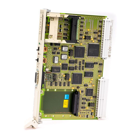
Design
5-42
This section contains the hardware description and technical specifications of
the CPU 928B.
Details on programming the CPU 928B can be found in the
CPU 928B Programming Guide.
You can use the CPU 928B in single and multiprocessor operation in the
S5-135U/155U central controller (see Chapter 6). Up to four CPUs can be
used.
The CPU 928B is universally applicable, ensuring both very fast
bit processing and very fast word processing:
Cyclic
Time-controlled (9 different timebases)
Real-time controlled
Interrupt-driven (hardware interrupt)
Delayed (from Version 6ES5 928-3UB12)
The programming language is STEP 5.
The electronic circuitry of the CPU 928B is on two PCBs (basic and
expansion boards) in the double Eurocard format. Both PCBs are screwed
together, linked via connectors, and must not be separated. The basic board
provides the connection to the S5 bus via two backplane connectors.
The front plate width is 2 2/3 standard plug-in stations.
System Manual
C79000-G8576-C199-07
Advertisement

Related Manuals for Siemens 928B


Summary of Contents for Siemens 928B
- Page 1 5.4.1 Technical Description Application You can use the CPU 928B in single and multiprocessor operation in the S5-135U/155U central controller (see Chapter 6). Up to four CPUs can be used. The CPU 928B is universally applicable, ensuring both very fast...
- Page 2 You can connect programmers and OPs to the first interface. This PG interface SI1 is permanently installed on the CPU. You can use PG interface SI1 either via the front connector of the CPU 928B or via the front connector of the 923C coordinator module.
- Page 3 A description of interface submodules can be found in Section 5.11, and the order numbers in the ordering information. A detailed description of the second interface can be found in the CPU 928B Communication Manual. Process Interrupt There is an interrupt line in the PLC for each CPU.
-
Page 4: Installation And Startup
Module Caution Switch off the power supply before removing or inserting the module. The basic board and expansion board of the CPU 928B are one unit and must not be separated. Insertion Proceed as follows to insert the CPU in the central controller:... - Page 5 Press the release lever downwards and pull the module forwards and out of the central controller. Note Only operate the CPU 928B with the submodule receptacle closed. You close it either by fitting an interface submodule or with the cover supplied. System Manual...
- Page 6 Interface Fault Indicator LEDs (red) Interface 1 Interface 2 BASP Order Number and Version Receptacle for Interface Submodule Interface SI 2 PG Interface, 15-Pin Interface SI 1 Release Lever Locking Pin Figure 5-6 Front Plate of the CPU 928B System Manual 5-47 C79000-G8576-C199-07...
-
Page 7: Overall Reset
In the RUN setting, the CPU 928B processes the user program when the green RUN LED is lit. STOP The CPU 928B goes to the stop state when you switch from RUN to STOP. The red STOP LED then lights up. Momentary-... - Page 8 CPU 928B in the area of the process image (IB 0 to 127, QB 0 to 127) and has been entered as present in the “9th track”...
- Page 9 Command output is inhibited and the digital outputs will be directly switched to the safe state. A detailed description of interrupt and error handling can be found in the CPU 928B Programming Guide. LED SI1 LED SI2 Cause No communication possible at both interfaces.
- Page 10 The CPU is now in the RUN state but still has no user program. Restart You can also carry out a manual restart of the CPU 928B with the mode switch. The CPU 928B Programming Guide will indicate when a manual restart is permissible.
-
Page 11: Technical Specifications
CPUs, Memory Cards, Memory Submodules, Interface Submodules 5.4.3 Technical Specifications Important for the USA and Canada The following approvals have been obtained: UL Listing Mark Underwriters Laboratories (UL) to Standard UL 508, Report E 85972 CSA Certification Mark Canadian Standard Association (CSA) to Standard C 22.2 No. 142, Report LR 63533 Degree of protection IP 00... - Page 12 CPUs, Memory Cards, Memory Submodules, Interface Submodules Organization blocks OB OB 1 to 39 (interfaces for operating system) Integrated special function organization See Pocket Guide blocks OB Integrated serial interface PG interface Optional serial interface Via interface submodules, optionally as V.24, TTY, RS 422A/485 or PG interface SINEC L1 interface from Version 6ES5 928-3UB12 Backplane bus...