Table of Contents
Advertisement
SIMATIC S7-300 CPU 31xC and CPU 31x, Technical Data
SIMATIC
S7-300
CPU 31xC and CPU 31x, Technical
Data
Manual
The following supplement is part of this documentation:
No.
Designation
1
Product Information
2
Product Information
This manual is included in the documentation package
with Order No.: 6ES7398-8FA10-8BA0
01/2006 Edition
A5E00105475-06
Edition
Drawing number
A5E00688649-02
03/2006
A5E00830174-01
07/2006
Preface
Guide to the S7-300
______________
documentation
Operating and display
______________
elements
______________
Communication
______________
Memory concept
______________
Cycle and reaction times
______________
Technical data of CPU 31xC
______________
Technical data of CPU 31x
______________
Appendix
1
2
3
4
5
6
7
A
Advertisement
Table of Contents

Related Manuals for Siemens CPU 31 Series


Summary of Contents for Siemens CPU 31 Series
- Page 1 Preface SIMATIC S7-300 CPU 31xC and CPU 31x, Technical Data Guide to the S7-300 ______________ documentation Operating and display ______________ elements SIMATIC ______________ Communication S7-300 CPU 31xC and CPU 31x, Technical ______________ Memory concept Data ______________ Cycle and reaction times Manual ______________ Technical data of CPU 31xC...
-
Page 2: A5E00105475
Trademarks All names identified by ® are registered trademarks of the Siemens AG. The remaining trademarks in this publication may be trademarks whose use by third parties for their own purposes could violate the rights of the owner. - Page 3 Preface Purpose of the Manual This manual contains all the information you will need concerning the configuration, communication, memory concept, cycle, response times and technical data for the CPUs. You will then learn the points to consider when upgrading to one of the CPUs discussed in this manual.
- Page 4 For information on the special features of the CPU 315F-2 DP (6ES7 315-6FF00-0AB0) and CPU 317F-2 DP (6ES7 317-6FF00-0AB0), refer to the product information in the Internet: http://support.automation.siemens.com under article ID 17015818. Note There you can obtain the descriptions of all current modules. For new modules, or modules of a more recent version, we reserve the right to include a Product Information containing latest information.
- Page 5 Preface CE label The SIMATIC S7-300 product series satisfies the requirements and safety specifications of the following EC Directives: • EC Directive 73/23/EEC "Low-voltage directive" • EC Directive 89/336/EEC "EMC directive" C tick mark The SIMATIC S7-300 product series is compliant with AS/NZS 2064 (Australia). Standards The SIMATIC S7-300 product series is compliant with IEC 61131-2.
- Page 6 Preface Name of the manual Description Getting Started The example used in this Getting Started The following Getting Started editions are available guides you through the various steps in as a collective volume: commissioning required to obtain a fully functional application. CPU 31x: Commissioning •...
- Page 7 Preface Recycling and Disposal The devices described in this manual can be recycled, due to their ecologically compatible components. For environment-friendly recycling and disposal of your old equipment, contact a certified disposal facility for electronic scrap. CPU 31xC and CPU 31x, Technical Data Manual, 01/2006 Edition, A5E00105475-06...
- Page 8 Preface CPU 31xC and CPU 31x, Technical Data viii Manual, 01/2006 Edition, A5E00105475-06...
-
Page 9: Table Of Contents
Table of contents Preface..............................iii Guide to the S7-300 documentation ....................... 1-1 Operating and display elements ......................2-1 Operating and display elements: CPU 31xC ................2-1 2.1.1 Operating and display elements: CPU 31xC ................2-1 2.1.2 Status and Error Indicators: CPU 31xC ..................2-4 Operating and display elements: CPU 31x................ - Page 10 Table of contents Memory concept ............................. 4-1 Memory areas and retentivity..................... 4-1 4.1.1 CPU memory areas........................4-1 4.1.2 Retentivity of load memory, system memory and RAM............. 4-2 4.1.3 Retentivity of memory objects ....................4-3 4.1.4 Address areas of system memory ..................... 4-4 4.1.5 Properties of the SIMATIC Micro Memory Card (MMC) ............
- Page 11 Table of contents CPU 314C-2 PtP and CPU 314C-2 DP ................... 6-21 Technical data of the integrated I/O..................6-28 6.6.1 Arrangement and usage of integrated I/Os................6-28 6.6.2 Analog I/O ..........................6-34 6.6.3 Parameterization ........................6-38 6.6.4 Interrupts ..........................6-43 6.6.5 Diagnostics..........................
- Page 12 Table of contents Tables Table 1 Application area covered by this manual ..................iii Table 1-1 Ambient influence on the automation system (AS)..............1-1 Table 1-2 Galvanic isolation ........................1-1 Table 1-3 Communication between sensors/actuators and the PLC............1-2 Table 1-4 The use of local and distributed I/O ...................
- Page 13 Table of contents Table 4-4 Address areas of system memory ..................... 4-5 Table 5-1 Cyclic program processing......................5-2 Table 5-2 Formula for calculating the process image (PI) transfer time ............ 5-4 Table 5-3 CPU 31xC: Data for calculating the process image (PI) transfer time........5-4 Table 5-4 CPU 31x: Data for calculating the process image (PI) transfer time .........
- Page 14 Table of contents CPU 31xC and CPU 31x, Technical Data Manual, 01/2006 Edition, A5E00105475-06...
-
Page 15: Guide To The S7-300 Documentation
Guide to the S7-300 documentation Overview There you find a guide leading you through the S7-300 documentation. Selecting and configuring Table 1-1 Ambient influence on the automation system (AS) Information on.. is available in ... What provisions do I have to make for AS installation S7-300, CPU 31xC and CPU 31x operating instructions: space? Installation: Configuring - Component dimensions... -
Page 16: Table 1-3 Communication Between Sensors/Actuators And The Plc
Guide to the S7-300 documentation Table 1-3 Communication between sensors/actuators and the PLC Information on.. is available in ... Which module is suitable for my sensor/actuator? For CPU: CPU 31xC and CPU 31x Manual, Technical Data For signal modules: Reference manual of your signal module How many sensors/actuators can I connect to the module? For CPU: CPU 31xC and CPU 31x Manual, technical data... -
Page 17: Table 1-6 Cpu Performance
Guide to the S7-300 documentation Table 1-6 CPU performance Information on.. is available in ... Which memory concept is best suited to my application? CPU 31xC and CPU 31x Manual, Technical Data How do I insert and remove Micro Memory Cards? S7-300, CPU 31xC and CPU 31x operating instructions: Installation: Commissioning –... -
Page 18: Table 1-9 Supplementary Features
Guide to the S7-300 documentation Table 1-9 Supplementary features Information on.. is available in ... How to implement monitor and modify functions For text-based displays: The relevant Manual (Human Machine Interface) For Operator Panels: The relevant Manual For WinCC: The relevant Manual How to integrate process control modules For PCS7: The relevant Manual What options are offered by redundant and fail-safe... -
Page 19: Operating And Display Elements
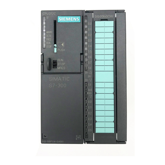
Operating and display elements Operating and display elements: CPU 31xC 2.1.1 Operating and display elements: CPU 31xC Operating and display elements of CPU 31xC CPU 31xC and CPU 31x, Technical Data Manual, 01/2006 Edition, A5E00105475-06... - Page 20 Operating and display elements 2.1 Operating and display elements: CPU 31xC The figures show the following CPU elements Status and error displays Slot for the SIMATIC Micro Memory Card (MMC) incl. the ejector Connections of the integrated I/O. Power supply connection 2.
- Page 21 Operating and display elements 2.1 Operating and display elements: CPU 31xC Slot for the SIMATIC Micro Memory Card (MMC) Memory module is a SIMATIC Micro Memory Card. You can use MMCs as load memory and as portable storage medium. Note These CPUs do not have an integrated load memory and thus require an SIMATIC Micro Memory Card for operation.
-
Page 22: Status And Error Indicators: Cpu 31Xc
Operating and display elements 2.1 Operating and display elements: CPU 31xC Differences between the CPUs Table 2-2 Differences of the CPUs 31xC Element 312C 313C 313C-2 PtP 314C-2 DP 314C-2 PtP 313C-2 DP 9-pole DP – – – – interface (X2) 15-pole PtP –... -
Page 23: Operating And Display Elements: Cpu 31X
Operating and display elements 2.2 Operating and display elements: CPU 31x Operating and display elements: CPU 31x 2.2.1 Operating and display elements: CPU 312, 314, 315-2 DP: Operating and display elements The figures show the following CPU elements Slot for the SIMATIC Micro Memory Card (MMC) incl. the ejector 2. -
Page 24: Table 2-3 Mode Selector Switch Settings
Operating and display elements 2.2 Operating and display elements: CPU 31x Slot for the SIMATIC Micro Memory Card (MMC) Memory module is a SIMATIC Micro Memory Card. You can use MMCs as load memory and as portable storage medium. Note These CPUs do not have an integrated load memory and thus require a SIMATIC Micro Memory Card for operation. -
Page 25: Operating And Display Elements: Cpu 317-2 Dp
Operating and display elements 2.2 Operating and display elements: CPU 31x 2.2.2 Operating and display elements: CPU 317-2 DP Operating and display elements The figures show the following CPU elements Bus error indicators Status and error displays Slot for the SIMATIC Micro Memory Card (MMC) incl. the ejector Mode selector switch Power supply connection 1. -
Page 26: Table 2-4 Mode Selector Switch Settings
Operating and display elements 2.2 Operating and display elements: CPU 31x Slot for the SIMATIC Micro Memory Card (MMC) Memory module is a SIMATIC Micro Memory Card. You can use MMCs as load memory and as portable storage medium. Note These CPUs do not have an integrated load memory and thus require a SIMATIC Micro Memory Card for operation. -
Page 27: Operating And Display Elements: Cpu 31X-2 Pn/Dp
Operating and display elements 2.2 Operating and display elements: CPU 31x 2.2.3 Operating and display elements: CPU 31x-2 PN/DP Operating and display elements The figures show the following CPU elements Bus error indicators Status and error displays Slot for the SIMATIC Micro Memory Card (MMC) incl. the ejector Mode selector switch Status display of 2nd interface (X2) 2. - Page 28 Operating and display elements 2.2 Operating and display elements: CPU 31x Slot for the SIMATIC Micro Memory Card (MMC) Memory module is a SIMATIC Micro Memory Card. You can use MMCs as load memory and as portable storage medium. Note These CPUs do not have an integrated load memory and thus require a SIMATIC Micro Memory Card for operation.
-
Page 29: Operating And Display Elements: Cpu 319-3 Pn/Dp
Operating and display elements 2.2 Operating and display elements: CPU 31x 2.2.4 Operating and display elements: CPU 319-3 PN/DP Operating and display elements The figures show the following CPU elements Bus error indicators Status and error displays Slot for the SIMATIC Micro Memory Card (MMC) incl. the ejector Mode selector switch 3. - Page 30 Operating and display elements 2.2 Operating and display elements: CPU 31x Slot for the SIMATIC Micro Memory Card (MMC) Memory module is a SIMATIC Micro Memory Card. You can use MMCs as load memory and as portable storage medium. Note These CPUs do not have an integrated load memory and thus require a SIMATIC Micro Memory Card for operation.
-
Page 31: Status And Error Displays Of Cpu 31X
Operating and display elements 2.2 Operating and display elements: CPU 31x 2.2.5 Status and error displays of CPU 31x General status and error displays Table 2-7 General status and error displays of the CPU 31x LED designation Color Meaning Hardware or software error. DC5 V green 5-V power for the CPU and the S7-300 bus... - Page 32 Operating and display elements 2.2 Operating and display elements: CPU 31x Reference STEP 7 Online Help. • CPU operating modes: Operating instructions CPU 31xC and CPU31x, • Information on CPU memory reset: Commissioning, Commissioning Modules, CPU Memory Reset by means of Mode Selector Switch Operating Instructions CPU 31xC •...
-
Page 33: Communication
Communication Interfaces 3.1.1 Multi-Point Interface (MPI) Availability All the CPUs described here are equipped with an MPI interface A CPU equipped with an MPI/DP interface is configured and supplied as MPI interface. To use the DP interface, set DP interface mode in STEP 7. -
Page 34: Profibus Dp
Communication 3.1 Interfaces Devices capable of MPI communication • PG/PC • OP/TP • S7-300 / S7-400 with MPI interface • S7-200 (19.2 kbps only) 3.1.2 PROFIBUS DP Availability CPUs with the "DP" have at least one DP interface. The 315-2 PN/DP and 317 CPUs are equipped with an MPI/DP interface. The CPU319-3 PN/DP has an MPI/DP interface and additionally a DP interface. -
Page 35: Profinet (Pn)
Communication 3.1 Interfaces Note (for DP interface in slave mode only) When you disable the Commissioning / Debug mode / Routing check box in the DP interface properties dialog in STEP 7, all user-specific transmission rate settings will be ignored, and the transmission rate of the master is automatically set instead. - Page 36 • For detailed information on Ethernet networks, network configuration and network SIMATIC NET Manual: Twisted-Pair and Fiber Optic Networks components refer to the available under article ID 8763736 at http://support.automation.siemens.com. Component Based Automation, Commissioning SIMATIC iMap Systems - Tutorial, •...
-
Page 37: Point To Point (Ptp)
Communication 3.1 Interfaces 3.1.4 Point to Point (PtP) Availability CPUs with the "PtP" name suffix have at least one PtP interface. Properties Using the PtP interface of your CPU, you can connect external devices with serial interface. You can operate such a system at transmission rates up to 19.2 kbps in full duplex mode (RS 422), and up to 38.4 kbps in half duplex mode (RS 485). -
Page 38: Communication Services
Communication 3.2 Communication services Communication services 3.2.1 Overview of communication services Selecting the communication service You need to decide on a communication service, based on functionality requirements. Your choice of communication service will have no effect on: • the functionality available, •... -
Page 39: Pg Communication
Communication 3.2 Communication services Communication service Functionality Time at which the S7 via MPI via DP connection is established ... PROFINET IO Data exchange between IO does not require an S7 – – – controllers and the IO connection devices SNMP Standard protocol for does not require an S7... -
Page 40: Op Communication
Communication 3.2 Communication services 3.2.3 OP communication Properties OP communication is used to exchange data between operator stations (OP, TP, for example) and SIMATIC modules which are capable of communication. This service is available for MPI, PROFIBUS and Industrial Ethernet subnets. OP communication provides functions you require for monitoring and modifying. -
Page 41: Global Data Communication (Mpi Only)
Communication 3.2 Communication services Table 3-3 Client and server in S7 communication, using connections with unilateral / bilateral configuration Use in server mode for Use in server mode for Use as client connections with unilateral connections with bilateral configuration configuration 31xC >= V1.0.0 Generally possible on Only possible with CP... -
Page 42: Table 1-7 Communication
Communication 3.2 Communication services Send and receive conditions Conditions which should be satisfied for GD communication: • For the transmitter of a GD packet: Reduction ratio x cycle time ≥ 60 ms transmitter transmitter • For the receiver of a GD packet: Reduction ratio x cycle time receiver... -
Page 43: Routing
Communication 3.2 Communication services 3.2.7 Routing Properties STEP 7 V5.1 + SP4 or higher allows you to access your S7 stations on all subnets with your PG/PC, for example, to • download user programs • download a hardware configuration, or •... - Page 44 Communication 3.2 Communication services The figure below shows the MPI access to PROFINET via PROFIBUS CPU 1 (315-2 DP, for example) is the router for subnet 1 and 2; CPU 2 is the router for subnet 2 and 3. Routing network nodes: MPI - DP - PROFINET CPU 31xC and CPU 31x, Technical Data 3-12 Manual, 01/2006 Edition, A5E00105475-06...
-
Page 45: Table 3-5 Number Of Routing Connections For Dp Cpus
Communication 3.2 Communication services Number of connections for routing The CPUs with DP interface provide a different number of connections for the routing function: Table 3-5 Number of routing connections for DP CPUs As of firmware version Number of connections for routing 31xC, CPU 31x 2.0.0 Max. - Page 46 Communication 3.2 Communication services Routing: Example of a TeleService application The figure below shows the example of an application for remote maintenance of an S7 station using a PG. The connection to other subnets is here established via modem connection. The lower section of the figure shows how to configure this in STEP 7.
-
Page 47: Point-To-Point Connection
Communication with SIMATIC • of a basic nature is contained in the Manual. • about the TeleService adapter is available under article ID 20983182 on the Internet URL http://support.automation.siemens.com. Instruction list • on SFCs, refer to STEP 7 Online Help... -
Page 48: Communication By Means Of Profinet
Communication 3.2 Communication services With PUT/GET functions For S7 communication functions, such as PUT/GET or write / read via OP communication, which do not require a block in the user program on the CPU (operating in server mode), allowances must be made in the program for the extent of the data consistency. The PUT/GET functions for S7 communication, or for reading/writing variables via OP communication, are executed at the CPU's scan cycle checkpoint. - Page 49 Numerous texts on the subject of PROFINET are available from the URL "http://www.profinet.com" from PROFIBUS International (formerly PROFIBUS Nutzer- Organisation, PNO) For further information, refer to Internet address " http://www.siemens.com\profinet\". What is PROFINET IO? Within the framework of PROFINET, PROFINET IO is a communication concept for the implementation of modular, distributed applications.
- Page 50 Communication 3.2 Communication services Extent of PROFINET CBA and PROFINET IO PROFINET IO and CBA represent two different views of automation devices on Industrial Ethernet. Figure 3-1 Extent of PROFINET IO and Component-Based Automation Component Based Automation divides the entire system into various functions. These functions are configured and programmed.
-
Page 51: Profinet Io System
Communication 3.2 Communication services 3.2.10.1 PROFINET IO System Extended Functions of PROFINET IO The following graphic shows the new functions of PROFINET IO The graphic displays Examples of connection paths The connection of company From PCs in your company network, you can access devices at the field level network and field level Example: PC - Switch 1 - Router - Switch 2 - CPU 31x PN/DP ①. -
Page 52: Blocks In Profinet Io
Communication 3.2 Communication services Reference For information From PROFIBUS DP to PROFINET IO programming manual. • on PROFINET refer to the This manual also provides a comprehensive overview of the new PROFINET blocks and system status lists. See also PROFINET (PN) (Page 3-3) 3.2.10.2 Blocks in PROFINET IO Content of this Section... - Page 53 Communication 3.2 Communication services Blocks PROFINET IO PROFIBUS DP SFB 52/53 (read/write data record) SFB 54 (evaluate interrupt) SFC102 (read predefined No (replacement: SFB81) parameters) SFB 81 (read predefined parameters) SFC5 (query start address of a No (replacement: SFC70) module) SFC 70 (query start address of a module) SFC49 (query the slot belonging...
-
Page 54: System Status Lists (Ssls) In Profinet Io
Communication 3.2 Communication services Comparison of the Organization Blocks of PROFINET IO and PROFIBUS DP Here, there are changes in OB 83 and OB 86, as shown in the following table. Table 3-8 OBs in PROFINET IO and PROFIBUS DP Blocks PROFINET IO PROFIBUS DP... -
Page 55: Table 3-9 Comparison Of The System Status Lists Of Profinet Io And Profibus Dp
Communication 3.2 Communication services Compatibility of the New System Status Lists For PROFINET IO, the system status lists had to be revamped to some extent because, among other things, larger configurations are now possible with PROFINET. You should also use these new system status lists with PROFIBUS. You can continue to use a known PROFIBUS system status list that is also supported by PROFINET. -
Page 56: Open Communication Via Industrial Ethernet
Communication 3.2 Communication services 3.2.10.4 Open communication via Industrial Ethernet Requirements • STEP 7 V5.3 + Servicepack 1 or higher Functionality The CPUs with integrated PROFINET interface as of firmware V2.3.0 or V2.4.0 support the open functionality of open communication by means of Industrial Ethernet (abbreviated: IE communication Following services are available for open IE communication: •... - Page 57 Communication 3.2 Communication services How to use open IE communication To allow data to be exchanged with other communication partners, STEP 7 provides the following FBs and UDTs under "Communication Blocks" in the "Standard Library": • Connection oriented protocols: TCP-native, ISO-on-TCP –...
- Page 58 Communication 3.2 Communication services Establishing a connection for communication • Use with TCP native and ISO on TOP Both communication partners call FB 65 "TCON" to establish the connection. In your connection configuration, you define which communication partner activates the connection, and which communication partner responds to the request with a passive connection.
-
Page 59: Snmp Communication Service
Communication 3.3 S7 connections 3.2.10.5 SNMP communication service Availability The SNMP communication service is available for CPUs with integrated PROFINET interface and Firmware 2.3.0 or higher. Properties SNMP (Simple Network Management Protocol)) is a standard protocol for TCP/IP networks. Reference For further information on the SNMP communication service and diagnostics with SNMP, PROFINET System Description. -
Page 60: Assignment Of S7 Connections
Communication 3.3 S7 connections Connection points An S7 connection between modules with communication capability is established between connection points. The S7 connection always has two connection points: The active and passive connection points: • The active connection point is assigned to the module that establishes the S7 connection. •... - Page 61 Communication 3.3 S7 connections Assigning connections in the program In S7 basic communication, and in open Industrial Ethernet communication with TCP/IP, the user program establishes the connection. The CPU operating system initiates the connection. S7 basic communication uses the corresponding S7 connections. The open IE communication does not use any S7 connections.
-
Page 62: Distribution And Availability Of S7 Connection Resources
Communication 3.3 S7 connections See also Open communication via Industrial Ethernet (Page 3-24) 3.3.3 Distribution and availability of S7 connection resources Distribution of connection resources Table 3-10 Distribution of connections Communication service Distribution PG communication In order to avoid allocation of connection resources being dependent only on the chronological sequence in which various communication services are OP communication requested, connection resources can be reserved for these services. -
Page 63: Table 3-11 Availability Of Connection Resources
Communication 3.3 S7 connections Availability of connection resources Table 3-11 Availability of connection resources Total number Reserved for Free connection S7 connections OP communication S7 basic resources communication communication 312C 1 to 5, default 1 1 to 5, default 1 0 to 2, default 2 Displays all non- reserved S7... -
Page 64: Connection Resources For Routing
Communication 3.3 S7 connections 3.3.4 Connection resources for routing Number of connection resources for routing The CPUs with DP interface provide a different number of connection resources for the routing function: Table 3-12 Number of routing connection resources (for DP/PN CPUs) As of firmware version Number of connections for routing 31xC, CPU 31x... -
Page 65: Dpv1
Communication 3.4 DPV1 Example for a CPU 317-2 PN/DP / CPU 319-3 PN/DP The CPU 317-2 PN/DP and CPU 319-3 PN/DP provide you with 32 connection resources (refer to Table 3-11): • Reserve four connection resources for PG communication. • Reserve six connection resources for OP communication. •... -
Page 66: Table 3-13 Interrupt Blocks With Dpv1 Functionality
Communication 3.4 DPV1 Requirement for using the DPV1 functionality with DP slaves For DPV1 slaves from other vendors, you will need a GSD file conforming to EN 50170, revision 3 or later. Extended functions of DPV1 • Use of any DPV1 slaves from external vendors (in addition to the existing DPV0 and S7 slaves, of course). - Page 67 Communication 3.4 DPV1 Note You can also use SFB 52 to SFB 54 for centralized I/O modules. SFBs 52 to 54 can also be used for PN IO. Reference For further information on the blocks mentioned earlier, refer to the reference manual System Software for S7-300/400: System and Standard Software STEP , or directly to the...
- Page 68 Communication 3.4 DPV1 CPU 31xC and CPU 31x, Technical Data 3-36 Manual, 01/2006 Edition, A5E00105475-06...
-
Page 69: Memory Concept
Memory concept Memory areas and retentivity 4.1.1 CPU memory areas The three memory areas of your CPU: Load memory The load memory is located on the SIMATIC Micro Memory Card (MMC). The size of the load memory corresponds exactly to the size of the SIMATIC Micro Memory Card. It is used to store code blocks, data blocks and system data (configuration, connections, module parameters, etc.). -
Page 70: Retentivity Of Load Memory, System Memory And Ram
Memory concept 4.1 Memory areas and retentivity System memory The RAM system memory is integrated in the CPU and cannot be expanded. It contains • the address areas for address area memory bits, timers and counters • the process image of the I/Os •... -
Page 71: Retentivity Of Memory Objects
Memory concept 4.1 Memory areas and retentivity Retentive data in RAM Therefore, the contents of retentive DBs are always retentive at restart and POWER ON/OFF. CPUs V2.1.0 or higher also support volatile DBs (the volatile DBs are initialized at restart of POWER OFF-ON with their initial values from load memory.) See also Properties of the SIMATIC Micro Memory Card (MMC) (Page 4-8) -
Page 72: Address Areas Of System Memory
Memory concept 4.1 Memory areas and retentivity Retentive behavior of a DB for CPUs with firmware >= V2.1.0 For these CPUs you can specify in STEP 7 (beginning with version 5.2 + SP 1), or at SFC 82 CREA_DBL (parameter ATTRIB -> NON_RETAIN bit), whether a DB at POWER ON/OFF or RUN-STOP •... - Page 73 Memory concept 4.1 Memory areas and retentivity Address areas of system memory Table 4-4 Address areas of system memory Address areas Description Process image of inputs At every start of an OB1 cycle, the CPU reads the values at the input of the input modules and saves them the process image of inputs.
- Page 74 Memory concept 4.1 Memory areas and retentivity Configurable process image with CPUs that have FW V2.3.0 or higher In STEP 7, you can define a user-specific size of the I/O process images between 0 to 2048 for the CPUs, FW V2.3.0 or higher. Note the information below: Note Currently, the dynamic setting of the process image only affects its update at the scan cycle...
- Page 75 Memory concept 4.1 Memory areas and retentivity Local data Local data store: • the temporary variables of code blocks • the start information of the OBs • transfer parameters • intermediate results Temporary Variables When you create blocks, you can declare temporary variables (TEMP) which are only available during block execution and then overwritten again.
-
Page 76: Properties Of The Simatic Micro Memory Card (Mmc)
Memory concept 4.1 Memory areas and retentivity 4.1.5 Properties of the SIMATIC Micro Memory Card (MMC) The SIMATIC Micro Memory Card (MMC) as memory module for the CPU The memory module used on your CPU is a SIMATIC Micro Memory Card. You can use MMCs as load memory or as a portable storage medium. - Page 77 Memory concept 4.1 Memory areas and retentivity SIMATIC Micro Memory Card (MMC) copy protection Your SIMATIC Micro Memory Card has an internal serial number that implements an MMC copy protection. You can read this serial number from the SSL partial list 011C index 8 using SFC 51 "RDSYSST."...
-
Page 78: Memory Functions
Memory concept 4.2 Memory functions Memory functions 4.2.1 General: Memory functions Memory functions Memory functions are used to generate, modify or delete entire user programs or specific blocks. You can also ensure that your project data are retained by archiving these. If you created a new user program, use a PG/PC to download the complete program to the SIMATIC Micro Memory Card. -
Page 79: Handling With Modules
Memory concept 4.2 Memory functions Note This function is only permitted when the CPU is in STOP mode. Load memory is cleared if the load operation could not be completed due to power loss or illegal block data. 4.2.3 Handling with modules 4.2.3.1 Download of new blocks or delta downloads There are two ways to download additional user blocks or download deltas:... -
Page 80: Deleting Blocks
Memory concept 4.2 Memory functions 4.2.3.3 Deleting blocks Deleting blocks When you delete a block, it is deleted from load memory. In STEP 7, you can also delete blocks with the user program (DBs also with SFC 23 "DEL_DB"). RAM used by this block is released. -
Page 81: Cpu Memory Reset And Restart
Memory concept 4.2 Memory functions 4.2.4 CPU memory reset and restart CPU memory reset After the insertion/removal of a Micro Memory Card, a CPU memory reset restores defined conditions for CPU restart (warm start). A CPU memory reset rebuilds the CPU's memory management. -
Page 82: Recipes
Memory concept 4.2 Memory functions 4.2.5 Recipes Introduction A recipe represents a collection of user data. You can implement a simple recipe concept using static DBs. In this case, the recipes should have the same structure (length). One DB should exist per recipe. Processing sequence Recipe is written to load memory: •... - Page 83 Memory concept 4.2 Memory functions Note As a precaution against loss of data, always make sure that you do not exceed the maximum number of delete/write operations. Also refer to the SIMATIC Micro Memory Card (MMC) section in the "Structure and Communication Connections of a CPU" chapter.
-
Page 84: Measured Value Log Files
Memory concept 4.2 Memory functions 4.2.6 Measured value log files Introduction Measured values are generated when the CPU executes the user program. These values are to be logged and analyzed. Processing sequence Acquisition of measured values: • The CPU writes all measured values to a DB (for alternating backup mode in several DBs) which is located in RAM. - Page 85 Memory concept 4.2 Memory functions Note Active system functions SFC82 to 84 (active access to the SIMATIC Micro Memory Card) have a distinct influence on PG functions (for example, block status, variable status, download block, upload, open.) This typically reduces performance (compared to passive system functions) by the factor 10.
-
Page 86: Backup Of Project Data To Simatic Micro Memory Card (Mmc)
Memory concept 4.2 Memory functions 4.2.7 Backup of project data to SIMATIC Micro Memory Card (MMC) Function principle Using the Save project to Memory Card and Fetch project from Memory Card functions, you can save all project data to a SIMATIC Micro Memory Card, and retrieve these at a later time. -
Page 87: Cycle And Reaction Times
Cycle and reaction times Overview Overview This section contains detailed information about the following topics: • Cycle time • Reaction time • Interrupt response time • Sample calculations Reference: Cycle time You can view the cycle time of your user program on the PG. For further information, refer to STEP 7 Online Help Configuring Hardware and Connections in STEP 7 , or to the... - Page 88 Cycle and reaction times 5.2 Cycle time Meaning of the term cycle time The cycle time represents the time that an operating system needs to execute a program, that is, one OB 1 cycle, including all program sections and system activities interrupting this cycle.
- Page 89 Cycle and reaction times 5.2 Cycle time In contrast to S7-400 CPUs, the S7-300 CPUs data only allow data access from an OP / TP (monitor and modify functions) at the scan cycle check point (Data consistency, see the Technical Data). Processing of the user program is not interrupted by the monitor and modify functions.
-
Page 90: Calculating The Cycle Time
Cycle and reaction times 5.2 Cycle time 5.2.2 Calculating the cycle time Introduction The cycle time is derived from the sum of the following influencing factors. Process image update The table below shows the time a CPU requires to update the process image (process image transfer time). - Page 91 Cycle and reaction times 5.2 Cycle time Table 5-4 CPU 31x: Data for calculating the process image (PI) transfer time Const. Components CPU 312 CPU 314 CPU 315 CPU 317 CPU 319 Base load 150 μs 100 μs 100 μs 50 μs 2 μs Per byte in the...
- Page 92 Cycle and reaction times 5.2 Cycle time Operating system processing time at the scan cycle check point The table below shows the operating system processing time at the scan cycle checkpoint of the CPUs. These times are calculated without taking into consideration times for: •...
-
Page 93: Different Cycle Times
Cycle and reaction times 5.2 Cycle time Extension of the cycle time due to error Table 5-8 Cycle time extension as a result of errors Type of error Programming errors I/O access errors 312C 600 μs 600 μs 313C 400 μs 400 μs 313C2 400 μs... -
Page 94: Communication Load
Cycle and reaction times 5.2 Cycle time Block processing times may fluctuate Fluctuation of the block processing time (e.g. OB 1) may also be a factor causing cycle time fluctuation, due to: • conditional instructions, • conditional block calls, • different program paths, •... - Page 95 Cycle and reaction times 5.2 Cycle time Example: 50 % communication load In your hardware configuration, you have specified a communication load of 50%. The calculated cycle time is 10 ms. Using the above formula, the cycle time is extended by the factor 2.
-
Page 96: Cycle Time Extension As A Result Of Testing And Commissioning Functions
Cycle and reaction times 5.2 Cycle time Tips • Use the default setting wherever possible. • Increase this value only if the CPU is used primarily for communications and if the user program is not time critical. • In all other situations you should only reduce this value. 5.2.5 Cycle time extension as a result of testing and commissioning functions Runtimes... - Page 97 Cycle and reaction times 5.2 Cycle time Extending the OB1 cycle time The OB1 cycle is extended by • Increasing the number of PROFINET interconnections, • Increasing the number of remote partners, • Increasing the data volume and • Incrasing the transfer frequency Note The use of CBA with cyclical PROFINET interconnections requires the use of switches to maintain the performance data.
- Page 98 Cycle and reaction times 5.2 Cycle time The upper graphic displays Quantity for CPU 315 and CPU 317 Quantity for CPU 319 Incoming/outgoing remote connections Cyclical interconnection via Ethernet 200, scan cycle rate: Intervals of 10 300, scan cycle rate: Intervals of 10 Acyclic interconnection via Ethernet 100, scan cycle rate: Intervals of 100, scan cycle rate: Intervals of 200...
-
Page 99: Response Time
Cycle and reaction times 5.3 Response time Tips and notes The upper graphic already includes the use of uniform values for the transfer frequency of all interconnections to a partner. • The performance can drop by up to 50 % if the values are distributed to different frequency levels. - Page 100 Cycle and reaction times 5.3 Response time DP cycle times in the PROFIBUS DP network If you have configured your PROFIBUS DP master system in STEP 7, STEP 7 calculates the typical DP cycle time to be expected. You can then view the DP cycle time of your configuration on the PG.
-
Page 101: Shortest Response Time
Cycle and reaction times 5.3 Response time 5.3.2 Shortest response time Conditions for the shortest response time The figure below shows the conditions under which the shortest response time is reached. Calculation The (shortest) response time is the sum of: Table 5-10 Formula: Shortest response time 1 x process image transfer time for the inputs... -
Page 102: Longest Response Time
Cycle and reaction times 5.3 Response time 5.3.3 Longest response time Conditions for the longest response time The figure below shows the conditions under which the longest response time is reached. CPU 31xC and CPU 31x, Technical Data 5-16 Manual, 01/2006 Edition, A5E00105475-06... -
Page 103: Reducing The Response Time With Direct I/O Access
Cycle and reaction times 5.3 Response time Calculation The (longest) response time is the sum of: Table 5-11 Formula: Longest response time 2 x process image transfer time for the inputs 2 x process image transfer time for the outputs 2 x program processing time 2 ×... -
Page 104: Calculating Method For Calculating The Cycle/Response Time
Cycle and reaction times 5.4 Calculating method for calculating the cycle/response time Calculating method for calculating the cycle/response time Introduction This section gives you an overview of how to calculate the cycle/response time. Cycle time Instruction list 1. Determine the user program runtime with the help of the Extension of user 2. - Page 105 Cycle and reaction times 5.4 Calculating method for calculating the cycle/response time Response time Table 5-12 Calculating the response time Shortest response time Longest response time Multiply the physical cycle time by factor 2. Now add I/O delay. Now add the I/O delay plus the DP cycle times on PROFIBUS-DP or the PROFINET IO update times.
-
Page 106: Interrupt Response Time
Cycle and reaction times 5.5 Interrupt response time Interrupt response time 5.5.1 Overview Definition of interrupt response time The interrupt response time is the time that expires between the first occurrence of an interrupt signal and the call of the first interrupt OB instruction. Generally valid: Higher- priority interrupts take priority. - Page 107 Cycle and reaction times 5.5 Interrupt response time Calculation The formula below show how you can calculate the minimum and maximum interrupt response times. Table 5-14 Process and diagnostic interrupt response times Calculation of the minimum and maximum interrupt reaction time Minimum interrupt reaction time of the CPU Maximum interrupt reaction time of the CPU + Minimum interrupt reaction time of the...
-
Page 108: Reproducibility Of Time-Delay And Watchdog Interrupts
Cycle and reaction times 5.6 Sample calculations 5.5.2 Reproducibility of Time-Delay and Watchdog Interrupts Definition of "Reproducibility" Delay interrupt: The period that expires between the call of the first instruction in the interrupt OB and the programmed time of interrupt. Watchdog interrupt: The fluctuation width of the interval between two successive calls, measured between the respective initial instructions of the interrupt OBs. -
Page 109: Sample Of Response Time Calculation
Cycle and reaction times 5.6 Sample calculations Calculating the cycle time The cycle time for the example results from the following times: • User program execution time: approx. 5 ms x CPU-specific factor 1.10 = approx. 5.5 ms • Process image transfer time Process image of inputs: 100 μs + 8 Byte x 37 μs = approx. - Page 110 Cycle and reaction times 5.6 Sample calculations User Program According to the instruction list, the user program runtime is 10.0 ms. Calculating the cycle time The cycle time for the example results from the following times: • User program execution time: approx.
-
Page 111: Example Of Interrupt Response Time Calculation
Cycle and reaction times 5.6 Sample calculations • Response times plus I/O delay: – Case 1: An output channel of the digital output module is set when a signal is received at the digital input. The result is a response time of: Response time = 42 ms + 4.8 ms = 46.8 ms. - Page 112 Cycle and reaction times 5.6 Sample calculations CPU 31xC and CPU 31x, Technical Data 5-26 Manual, 01/2006 Edition, A5E00105475-06...
-
Page 113: Technical Data Of Cpu 31Xc
Technical data of CPU 31xC General technical data 6.1.1 Dimensions of CPU 31xC Each CPU features the same height and depth, only the width dimensions differ. • Height: 125 mm • Depth: 115 mm, or 180 mm with opened front cover. Width of CPU Width CPU 312C... -
Page 114: Technical Specifications Of The Micro Memory Card (Mmc)
Technical data of CPU 31xC 6.1 General technical data 6.1.2 Technical specifications of the Micro Memory Card (MMC) Plug-in SIMATIC Micro Memory Card (MMC) The following memory modules are available: Table 6-1 Available SIMATIC Micro Memory Cards Type Order number Required for a firmware update via SIMATIC Micro Memory Card MMC 64k... -
Page 115: Cpu 312C
Technical data of CPU 31xC 6.2 CPU 312C CPU 312C Technical data Table 6-3 Technical data of CPU 312C Technical data CPU and version Order number 6ES7 312-5BD01-0AB0 Hardware version • Firmware version • V2.0 Associated programming package • STEP 7 as of V 5.2 + SP 1 (please use previous CPU for STEP 7 V 5.1 + SP 3 or later) Memory... - Page 116 Technical data of CPU 31xC 6.2 CPU 312C Technical data Data areas and their retentivity Flag bits 128 bytes Retentive address areas • Configurable Default retentivity • MB0 to MB15 Clock flag bits 8 (1 byte per flag bit) Data blocks Max.
- Page 117 Technical data of CPU 31xC 6.2 CPU 312C Technical data Number of function modules and communication processors you can operate Max. 8 • CP (PtP) • Max. 8 CP (LAN) • Max. 4 Time-of-day Real-time clock Yes (SW clock) Buffered •...
- Page 118 Technical data of CPU 31xC 6.2 CPU 312C Technical data Communication functions PG/OP communication Global data communication Number of GD circuits • Number of GD packets • Max. 4 Sending stations Max. 4 – Receiving stations – Max. 4 Length of GD packets •...
- Page 119 Technical data of CPU 31xC 6.2 CPU 312C Technical data Services PG/OP communication • Routing • Global data communication • S7 basic communication • S7 communication • As server – As client – Transmission rates • Max. 187.5 kbps Programming Programming language LAD/FBD/STL Available instructions...
-
Page 120: Cpu 313C
Technical data of CPU 31xC 6.3 CPU 313C Reference Specifications of the integrated I/O In Chapter you can find Digital inputs of CPUs 31xC Digital outputs • the specifications of integrated I/Os under of CPUs 31xC Arrangement and usage of integrated •... - Page 121 Technical data of CPU 31xC 6.3 CPU 313C Technical data IEC Counters Type • Number • unlimited (limited only by RAM size) S7 timers Retentive address areas • Configurable Default • Not retentive Timer range • 10 ms to 9990 s IEC timers Type •...
- Page 122 Technical data of CPU 31xC 6.3 CPU 313C Technical data Digital channels Max. 1016 Centralized • Max. 992 Integrated channels • 24 DI / 16 DO Analog channels Max. 253 Centralized • Max. 248 Integrated channels • 4 + 1 AI / 2 AO Removal Module rack Max.
- Page 123 Technical data of CPU 31xC 6.3 CPU 313C Technical data Test and startup functions Status/control variables Variables • Inputs, outputs, memories, DBs, timers, counters Number of variables • Max. 30 of those as status variable – Max. 30 of those as control variable –...
- Page 124 Technical data of CPU 31xC 6.3 CPU 313C Technical data S7 basic communication • Max. 4 Reserved (default) – Configurable – From 0 to 4 Routing interfaces 1st interface Type of interface Integrated RS485 interface Physics RS 485 electrically isolated Interface power supply Max.
- Page 125 Technical data of CPU 31xC 6.3 CPU 313C Technical data Controlled positioning Technological Functions Integrated "Controlling" SFB PID controller (see the manual) Dimensions Mounting dimensions W x H x D (mm) 120 x 125 x 130 Weight 660 g Voltages, currents Power supply (rated value) DC 24 V Permitted range...
-
Page 126: Cpu 313C-2 Ptp And Cpu 313C-2 Dp
Technical data of CPU 31xC 6.4 CPU 313C-2 PtP and CPU 313C-2 DP CPU 313C-2 PtP and CPU 313C-2 DP Technical Data Table 6-5 Technical data for CPU 313C-2 PtP/ CPU 313C-2 DP Technical data CPU 313C-2 PtP CPU 313C-2 DP CPU and version CPU 313C-2 PtP CPU 313C-2 DP... - Page 127 Technical data of CPU 31xC 6.4 CPU 313C-2 PtP and CPU 313C-2 DP Technical data CPU 313C-2 PtP CPU 313C-2 DP IEC timers Type • Number • unlimited (limited only by RAM size) Data areas and their retentive address CPU 313C-2 PtP CPU 313C-2 DP areas Bit memory...
- Page 128 Technical data of CPU 31xC 6.4 CPU 313C-2 PtP and CPU 313C-2 DP Technical data CPU 313C-2 PtP CPU 313C-2 DP Removal CPU 313C-2 PtP CPU 313C-2 DP Module rack Max. 4 Modules per rack Max. 8; Max. 7 in rack 3 Number of DP masters Integrated •...
- Page 129 Technical data of CPU 31xC 6.4 CPU 313C-2 PtP and CPU 313C-2 DP Technical data CPU 313C-2 PtP CPU 313C-2 DP Block status Single-step Breakpoints Diagnostic buffer Number of entries (not configurable) • Max. 100 Communication functions CPU 313C-2 PtP CPU 313C-2 DP PG/OP communication Global data communication...
- Page 130 Technical data of CPU 31xC 6.4 CPU 313C-2 PtP and CPU 313C-2 DP Technical data CPU 313C-2 PtP CPU 313C-2 DP Functionality • PROFIBUS DP • Point-to-point connection • Services PG/OP communication • Routing • Global data communication • S7 basic communication •...
- Page 131 • – Max. 32, with Max. 32 bytes each DPV1 • – GSD file – The latest GSD file is available at: http://www.automation.siemens.com/ csi/gsd Point-to-point connection Transmission rates • 38.4 Kbaud half duplex – 19.2 Kbaud full duplex Cable length •...
- Page 132 Technical data of CPU 31xC 6.4 CPU 313C-2 PtP and CPU 313C-2 DP Technical data CPU 313C-2 PtP CPU 313C-2 DP Technological Functions Integrated "Controlling" SFB PID controller (see the manual) Dimensions CPU 313C-2 PtP CPU 313C-2 DP Mounting dimensions W x H x D (mm) 120 x 125 x 130 Weight approx.
-
Page 133: Cpu 314C-2 Ptp And Cpu 314C-2 Dp
Technical data of CPU 31xC 6.5 CPU 314C-2 PtP and CPU 314C-2 DP CPU 314C-2 PtP and CPU 314C-2 DP Technical Data Table 6-6 Technical data of CPU 314C-2 PtP and CPU 314C-2 DP Technical data CPU 314C-2 PtP CPU 314C-2 DP CPU and version CPU 314C-2 PtP CPU 314C-2 DP... - Page 134 Technical data of CPU 31xC 6.5 CPU 314C-2 PtP and CPU 314C-2 DP Technical data CPU 314C-2 PtP CPU 314C-2 DP IEC Timers Type • Number • unlimited (limited only by RAM size) Data areas and their retentivity CPU 314C-2 PtP CPU 314C-2 DP Flag bits 256 bytes...
- Page 135 Technical data of CPU 31xC 6.5 CPU 314C-2 PtP and CPU 314C-2 DP Technical data CPU 314C-2 PtP CPU 314C-2 DP Assembly CPU 314C-2 PtP CPU 314C-2 DP Racks Max. 4 Modules per rack Max. 8; Max. 7 in rack 3 Number of DP masters Integrated •...
- Page 136 Technical data of CPU 31xC 6.5 CPU 314C-2 PtP and CPU 314C-2 DP Technical data CPU 314C-2 PtP CPU 314C-2 DP Forcing Variables • Inputs, outputs Number of variables • Max. 10 Block status Single step Breakpoints Diagnostic buffer Number of entries (not configurable) Max. 100 •...
- Page 137 Technical data of CPU 31xC 6.5 CPU 314C-2 PtP and CPU 314C-2 DP Technical data CPU 314C-2 PtP CPU 314C-2 DP Interfaces CPU 314C-2 PtP CPU 314C-2 DP 1st interface Type of interface Integrated RS485 interface Physics RS 485 electrically isolated Interface power supply (15 to 30 VDC) Max.
- Page 138 Address areas • Max. 32, with Max. 32 bytes each DPV1 • – GSD file – The latest GSD file is available at: http://www.automation.siemens.com/csi/ Point-to-point connection Transmission rates • 38.4 Kbaud half duplex – 19.2 Kbaud full duplex Cable length •...
- Page 139 Technical data of CPU 31xC 6.5 CPU 314C-2 PtP and CPU 314C-2 DP Technical data CPU 314C-2 PtP CPU 314C-2 DP Integrated I/O CPU 314C-2 PtP CPU 314C-2 DP Default addresses of the integrated • Digital inputs 124.0 to 126.7 –...
-
Page 140: Technical Data Of The Integrated I/O
Technical data of CPU 31xC 6.6 Technical data of the integrated I/O Technical data of the integrated I/O 6.6.1 Arrangement and usage of integrated I/Os Introduction Integrated I/Os of CPUs 31xC can be used for technological functions or as standard I/O. The figures below illustrate possible usage of I/Os integrated in the CPUs. - Page 141 Technical data of CPU 31xC 6.6 Technical data of the integrated I/O Block diagram of the integrated digital I/O CPU 31xC and CPU 31x, Technical Data 6-29 Manual, 01/2006 Edition, A5E00105475-06...
- Page 142 Technical data of CPU 31xC 6.6 Technical data of the integrated I/O CPU 313C, CPU 313C-2 DP/PtP, CPU 314C-2 DP/PtP: DI/DO (connectors X11 and X12) Z0 (A) DI+0.0 DO+0.0 Z0 (B) DI+0.1 DO+0.1 Z0(HW-gate) DI+0.2 DO+0.2 Z1 (A) Tast 0 DI+0.3 DO+0.3 Z1(B)
- Page 143 Technical data of CPU 31xC 6.6 Technical data of the integrated I/O Block diagram of integrated digital I/O of CPUs 313C/313C-2/314C-2 CPU 31xC and CPU 31x, Technical Data 6-31 Manual, 01/2006 Edition, A5E00105475-06...
- Page 144 Technical data of CPU 31xC 6.6 Technical data of the integrated I/O CPU 313C/314C-2: Pin-out of the integrated AI/AO and DI (connector X11) CPU 31xC and CPU 31x, Technical Data 6-32 Manual, 01/2006 Edition, A5E00105475-06...
- Page 145 Technical data of CPU 31xC 6.6 Technical data of the integrated I/O Block diagram of integrated digital/analog I/O of CPUs 313C/314C-2 Simultaneous usage of technological functions and standard I/O Technological functions and standard I/O can be used simultaneously with appropriate hardware.
-
Page 146: Analog I/O
Technical data of CPU 31xC 6.6 Technical data of the integrated I/O 6.6.2 Analog I/O Wiring of the current/voltage inputs The figure below shows the wiring diagram of the current/voltage inputs operated with 2-/4- wire measuring transducers. Figure 6-1 Connection of a 2-wire measuring transducer to an analog current/voltage input of CPU 313C/314C-2 Figure 6-2 Connection of a 4-wire measuring transducer to an analog current/voltage input of... - Page 147 Technical data of CPU 31xC 6.6 Technical data of the integrated I/O Integrated hardware low-pass filter An integrated low-pass filter attenuates analog input signals of channel 0 to 3. They are attenuated according to the trend in the figure below. Figure 6-3 Low-pass characteristics of the integrated filter Note...
- Page 148 Technical data of CPU 31xC 6.6 Technical data of the integrated I/O Figure 6-4 Principle of interference suppression with STEP 7 In the two graphics below we illustrate how the 50 Hz and 60 Hz interference suppression work Figure 6-5 50 Hz interference suppression CPU 31xC and CPU 31x, Technical Data 6-36...
- Page 149 Technical data of CPU 31xC 6.6 Technical data of the integrated I/O Figure 6-6 60 Hz interference suppression Note If the interference frequency is not 50/60 Hz or a multiple thereof, the input signal must be filtered externally, In this case, 400 Hz frequency suppression must be configured for the respective input. This is equivalent to a "Deactivation"...
-
Page 150: Parameterization
Technical data of CPU 31xC 6.6 Technical data of the integrated I/O 6.6.3 Parameterization Introduction You configure the integrated I/O of CPU 31xC with STEP 7. Always make these settings when the CPU is in STOP. The generated parameters are downloaded from the PG to the S7-300 and written to CPU memory . - Page 151 Technical data of CPU 31xC 6.6 Technical data of the integrated I/O Figure 6-7 Structure of record 1 for standard DI and interrupt inputs (length of 10 bytes) Parameters of standard DO There are no parameters for standard digital outputs. CPU 31xC and CPU 31x, Technical Data 6-39 Manual, 01/2006 Edition, A5E00105475-06...
- Page 152 Technical data of CPU 31xC 6.6 Technical data of the integrated I/O Parameters of standard AI The table below gives you an overview of the parameters for standard analog inputs. Table 6-9 Parameters of standard AI Parameters Value range Default Range of efficiency Integration time (ms) 2,5/16,6/20...
- Page 153 Technical data of CPU 31xC 6.6 Technical data of the integrated I/O CPU 31xC and CPU 31x, Technical Data 6-41 Manual, 01/2006 Edition, A5E00105475-06...
- Page 154 Technical data of CPU 31xC 6.6 Technical data of the integrated I/O Figure 6-8 Structure of record 1 for standard AI/AO (length of 13 bytes) Parameter for technological functions Technological Functions The parameters for the respective function are found in the Manual CPU 31xC and CPU 31x, Technical Data 6-42 Manual, 01/2006 Edition, A5E00105475-06...
-
Page 155: Interrupts
Technical data of CPU 31xC 6.6 Technical data of the integrated I/O 6.6.4 Interrupts Interrupt inputs All digital inputs of the on-board I/O of CPUs 31xC can be used as interrupt inputs. You can specify interrupt behavior for each individual input in your parameter declaration. Options are: •... -
Page 156: Diagnostics
Technical data of CPU 31xC 6.6 Technical data of the integrated I/O Start information for OB40 The table below shows the relevant temporary variables (TEMP) of OB40 for the interrupt inputs of 31xC CPUs. A description of process interrupt OB 40 is found in the Reference System and Standard Functions Manual Table 6-11... -
Page 157: Digital Inputs
Technical data of CPU 31xC 6.6 Technical data of the integrated I/O 6.6.6 Digital inputs Introduction This section provides the specifications for the digital inputs of CPUs 31xC. The table includes the following CPUs: • under CPU 313C-2, the CPU 313C-2 DP and CPU 313C-2 PtP •... - Page 158 Technical data of CPU 31xC 6.6 Technical data of the integrated I/O Technical data CPU 312C CPU 313C CPU 313C-2 CPU 314C-2 Status, interrupts, diagnostics CPU 312C CPU 313C CPU 313C-2 CPU 314C-2 Status display green LED per channel Yes, if the corresponding channel is configured as interrupt input Interrupts •...
-
Page 159: Digital Outputs
Technical data of CPU 31xC 6.6 Technical data of the integrated I/O 6.6.7 Digital outputs Introduction This chapter contains the specifications for the digital outputs of CPUs 31xC. The table includes the following CPUs: • under CPU 313C-2, the CPU 313C-2 DP and CPU 313C-2 PtP •... - Page 160 Technical data of CPU 31xC 6.6 Technical data of the integrated I/O Technical data CPU 312C CPU 313C CPU 313C-2 CPU 314C-2 Current consumption with load voltage L+ • Max. 50 mA Max. 100 mA Max. 100 mA Max. 100 mA Status, interrupts, diagnostics CPU 312C CPU 313C...
-
Page 161: Analog Inputs
Technical data of CPU 31xC 6.6 Technical data of the integrated I/O 6.6.8 Analog inputs Introduction This chapter contains the specifications for analog outputs of CPUs 31xC. The table includes the following CPUs: • CPU 313C • CPU 314C-2 DP •... - Page 162 Technical data of CPU 31xC 6.6 Technical data of the integrated I/O Technical data Interference suppression, error limits Interference voltage suppression for f = nx (f1 ± 1 %), (f1 = interference frequency), n = 1, 2 Commonmode interference (U <...
-
Page 163: Analog Outputs
Technical data of CPU 31xC 6.6 Technical data of the integrated I/O Technical data Connection of signal generators For voltage measurement • possible For current measurement • as 2-wire measuring transducer – Possible, with external power supply as 4-wire measuring transducer –... - Page 164 Technical data of CPU 31xC 6.6 Technical data of the integrated I/O Technical data Permitted potential difference between M and M • 75 VDC / 60 VAC internal Insulation test voltage 600 VDC Analog value generation Resolution (including overdrive) 11 bits + signed bit Conversion time (per channel) 1 ms Settling time...
- Page 165 Technical data of CPU 31xC 6.6 Technical data of the integrated I/O Technical data Voltage output Short-circuit protection • Short-circuit current • Typically 55 mA Current output No-load voltage • Typically 17 V Destruction limit for externally applied voltages/currents Voltage measured between the outputs and M •...
- Page 166 Technical data of CPU 31xC 6.6 Technical data of the integrated I/O CPU 31xC and CPU 31x, Technical Data 6-54 Manual, 01/2006 Edition, A5E00105475-06...
-
Page 167: Technical Data Of Cpu 31X
Technical data of CPU 31x General technical data 7.1.1 Dimensions of CPU 31x Each CPU features the same height and depth, only the width dimensions differ. • Height: 125 mm • Depth: 115 mm, or 180 mm with opened front cover. Figure 7-1 Dimensions of CPU 31x CPU 31xC and CPU 31x, Technical Data... -
Page 168: Technical Specifications Of The Simatic Micro Memory Card (Mmc)
Technical data of CPU 31x 7.1 General technical data Width of CPU Width CPU 312 40 mm CPU 314 40 mm CPU 315-2 DP 40 mm CPU 315-2 PN/DP 80 mm CPU 317-2 DP 80 mm CPU 317-2 PN/DP 80 mm CPU 319 120 mm 7.1.2... -
Page 169: Cpu 312
Technical data of CPU 31x 7.2 CPU 312 Table 7-2 Maximum number of loadable blocks on the SIMATIC Micro Memory Card Size of SIMATIC Micro Memory Maximum number of blocks that can be loaded Card 64 KB 128 KB 1024 512 KB Here the maximum number of blocks that can be loaded for the specific CPU is less than the number of blocks that can be... - Page 170 Technical data of CPU 31x 7.2 CPU 312 Technical data IEC Counters Type • Number • unlimited (limited only by RAM size) S7 timers Retentive address areas • Configurable Default • Not retentive Timer range • 10 ms to 9990 s IEC timers Type •...
- Page 171 Technical data of CPU 31x 7.2 CPU 312 Technical data Analog channels Max. 64 Of those central Max. 64 Removal Module rack Max. 1 Modules per rack Max. 8 Number of DP masters Integrated • None Via CP • Operable function modules and communication processors •...
- Page 172 Technical data of CPU 31x 7.2 CPU 312 Technical data Force Variables • Inputs, outputs Number of variables • Max. 10 Block status Single-step Breakpoints Diagnostic buffer Number of entries (not configurable) • Max. 100 Communication functions PG/OP communication Global data communication Number of GD circuits •...
- Page 173 Technical data of CPU 31x 7.2 CPU 312 Technical data Interface power supply Max. 200 mA (15 to 30 VDC) Functionality • PROFIBUS DP • Point-to-point connection • Services PG/OP communication • Routing • Global data communication • S7 basic communication •...
-
Page 174: Cpu 314
Technical data of CPU 31x 7.3 CPU 314 CPU 314 Technical data for the CPU 314 Table 7-4 Technical data for the CPU 314 Technical data CPU and version Order no. [MLFB] 6ES7314-1AF11-0AB0 Hardware version • Firmware version • V 2.0.0 Associated programming package •... - Page 175 Technical data of CPU 31x 7.3 CPU 314 Technical data Data areas and their retentive address areas Bit memory 256 bytes Retentive address areas • Preset retentive address areas • MB0 to MB15 Clock memory 8 (1 memory byte) Data blocks Number •...
- Page 176 Technical data of CPU 31x 7.3 CPU 314 Technical data Operable function modules and communication processors • Max. 8 CP (PtP) • Max. 8 CP (LAN) • Max. 10 Time Clock Yes (HW clock) Buffered • Buffered period • Typically 6 weeks (at an ambient temperature of 104 °F) Behavior of the clock on expiration of the •...
- Page 177 Technical data of CPU 31x 7.3 CPU 314 Technical data Diagnostic buffer Number of entries (not configurable) • Max. 100 Communication functions PG/OP communication Global data communication Number of GD circuits • Number of GD packets • Max. 4 Sender –...
- Page 178 Technical data of CPU 31x 7.3 CPU 314 Technical data Functionality • PROFIBUS DP • Point-to-point connection • Services PG/OP communication • Routing • Global data communication • S7 basic communication • S7 communication • As server – As client –...
-
Page 179: Cpu 315-2 Dp
Technical data of CPU 31x 7.4 CPU 315-2 DP CPU 315-2 DP Technical data Table 7-5 Technical data for the CPU 315-2 DP Technical data CPU and version Order no. [MLFB] 6ES7315-2AG10-0AB0 Hardware version • Firmware version • V 2.0.0 Associated programming package •... - Page 180 Technical data of CPU 31x 7.4 CPU 315-2 DP Technical data Data areas and their retentive address areas Bit memory 2048 bytes Retentive address areas • Preset retentive address areas • MB0 to MB15 Clock memory 8 (1 memory byte) Data blocks Number •...
- Page 181 Technical data of CPU 31x 7.4 CPU 315-2 DP Technical data Operable function modules and communication processors Max. 8 • CP (PtP) • Max. 8 CP (LAN) • Max. 10 Time Clock Yes (HW clock) Buffered • Buffered period • Typically 6 weeks (at an ambient temperature of 40 °C) Behavior of the clock on expiration of the...
- Page 182 Technical data of CPU 31x 7.4 CPU 315-2 DP Technical data Diagnostic buffer Number of entries (not configurable) • Max. 100 Communication functions PG/OP communication Global data communication Number of GD circuits • Number of GD packets • Max. 8 Sender –...
- Page 183 Technical data of CPU 31x 7.4 CPU 315-2 DP Technical data Functionality • PROFIBUS DP • Point-to-point connection • Services PG/OP communication • Routing • Global data communication • S7 basic communication • S7 communication • As server – As client –...
- Page 184 • Address areas • Max. 32 with Max. 32 bytes each DPV1 • GSD file The latest GSD file is available at: http://www.automation.siemens.com/csi/gsd Programming Programming language LAD/FBD/STL Instruction set See the Instruction List Nesting levels System functions (SFC) See the Instruction List...
-
Page 185: Cpu 315-2 Pn/Dp
Technical data of CPU 31x 7.5 CPU 315-2 PN/DP CPU 315-2 PN/DP Technical data Table 7-6 Technical data for the CPU 315-2 PN/DP Technical data CPU and version Order no. [MLFB] 6ES7315-2EG10-0AB0 Hardware version • Firmware version • V 2.3.0 Associated programming package •... - Page 186 Technical data of CPU 31x 7.5 CPU 315-2 PN/DP Technical data IEC timers Type • Number • Unlimited (limited only by work memory) Data areas and their retentive address areas Bit memory 2048 bytes Retentive address areas • Configurable Preset retentive address areas •...
- Page 187 Technical data of CPU 31x 7.5 CPU 315-2 PN/DP Technical data Removal Module rack Max. 4 Modules per rack Number of DP masters Integrated • Via CP • Operable function modules and communication processors • Max. 8 CP (PtP) • Max.
- Page 188 Technical data of CPU 31x 7.5 CPU 315-2 PN/DP Technical data Test and startup functions Status/control variables Variables • Inputs, outputs, memory bits, DBs, timers, counters Number of variables • Of those as status variable – Max. 30 Of those as control variable –...
- Page 189 Technical data of CPU 31x 7.5 CPU 315-2 PN/DP Technical data OP communication • Max. 15 Reserved (default) – Configurable – 1 to 15 S7-based communication • Max. 14 Reserved (default) – Configurable – 0 to 14 Routing Interface X1 configured as •...
- Page 190 Technical data of CPU 31x 7.5 CPU 315-2 PN/DP Technical data Functionality • PROFIBUS DP • Point-to-point connection • PROFINET • Services PG/OP communication • Routing • Global data communication • S7 basic communication • S7 communication • As server –...
- Page 191 PG functions • OP functions • Open IE communication via TCP/IP • GSD file The latest GSD file is available at: http://www.automation.siemens.com/csi/gsd Programming Programming language LAD/FBD/STL Instruction set See the Instruction List Nesting levels System functions (SFC) See the Instruction List...
-
Page 192: Cpu 317-2 Dp
Technical data of CPU 31x 7.6 CPU 317-2 DP Technical data Weight 460 g Voltages, currents Power supply (rated value) DC 24 V Permissible range • 20.4 V to 28.8 V Current consumption (no-load operation) 100 mA Making current Typically 2.5 A Min. - Page 193 Technical data of CPU 31x 7.6 CPU 317-2 DP Technical Data Retentive memory • Configurable Default • from C0 to C7 Counting range • 0 to 999 IEC Counters Type • Number • Unlimited (limited only by work memory) S7 timers Retentive memory •...
- Page 194 Technical data of CPU 31x 7.6 CPU 317-2 DP Technical Data See the Instruction List Number • 2048 (in the 0 to 2047 range of numbers) Size • 64 KB Address areas (I/O) Total I/O address area Max. 8192 bytes / 8192 bytes (can be freely addressed) Distributed Max.
- Page 195 Technical data of CPU 31x 7.6 CPU 317-2 DP Technical Data S7 signaling functions Number of stations that can be logged on for signaling functions (depends on the number of connections configured for PG / OP and S7 basic communication) Process diagnostics messages Simultaneously enabled interrupt S blocks •...
- Page 196 Technical data of CPU 31x 7.6 CPU 317-2 DP Technical Data can be used for PG communication • Maximum 31 Reserved (default) – Configurable – 1 to 31 OP communication • Maximum 31 Reserved (default) – Configurable – 1 to 31 S7-based communication •...
- Page 197 Technical data of CPU 31x 7.6 CPU 317-2 DP Technical Data Number of DP slaves Address range per DP slave Max. 244 bytes DP master (except for DP slave at both interfaces) Services Routing • Yes (only if interface is active) Global data communication •...
- Page 198 244 bytes I / 244 bytes O Address areas • Max. 32 with Max. 32 bytes each DPV1 • GSD file The latest GSD file is available at: http://www.automation.siemens.com/csi/gsd Programming Programming language LAD/FBD/STL Available instructions See the Instruction List Nesting levels System functions (SFCs)
-
Page 199: Cpu 317-2 Pn/Dp
Technical data of CPU 31x 7.7 CPU 317-2 PN/DP CPU 317-2 PN/DP Technical Data Table 7-8 Technical data for the CPU 317-2 PN/DP Technical Data CPU and version Order number 6ES7317-2EJ10-0AB0 Hardware version • Firmware version • V 2.3.0 Associated programming package •... - Page 200 Technical data of CPU 31x 7.7 CPU 317-2 PN/DP Technical Data IEC Timers Type • Number • Unlimited (limited only by work memory) Data areas and their retentivity Flag bits 4096 bytes Retentive memory • Configurable Default retentivity • From MB0 to MB15 Clock flag bits 8 (1 byte per flag bit) Data blocks...
- Page 201 Technical data of CPU 31x 7.7 CPU 317-2 PN/DP Technical Data Of those central 256/256 Assembly Racks Max. 4 Modules per rack Number of DP masters Integrated • via CP • Number of function modules and communication processors you can operate •...
- Page 202 Technical data of CPU 31x 7.7 CPU 317-2 PN/DP Technical Data Testing and commissioning functions Status/control variables Variables • Inputs, outputs, memory bits, DBs, timers, counters Number of variables • Of those as status variable – Maximum 30 Of those as control variable –...
- Page 203 Technical data of CPU 31x 7.7 CPU 317-2 PN/DP Technical Data OP communication • Maximum 31 Reserved (default) – Configurable – 1 to 31 S7-based communication • Maximum 30 Reserved (default) – Configurable – 0 to 30 Routing Interface X1 configured as •...
- Page 204 Technical data of CPU 31x 7.7 CPU 317-2 PN/DP Technical Data Functionality • PROFIBUS DP • Point-to-point connection • PROFINET • Services PG/OP communication • Routing • Global data communication • S7 basic communication • S7 communication • As server –...
- Page 205 PG functions • OP functions • Open IE communication via TCP/IP • GSD file The latest GSD file is available at: http://www.automation.siemens.com/csi/gsd Programming Programming language LAD/FBD/STL Available instructions See the Instruction List Nesting levels System functions (SFCs) See the Instruction List...
-
Page 206: Cpu 319-3 Pn/Dp
Technical data of CPU 31x 7.8 CPU 319-3 PN/DP Technical Data Dimensions Mounting dimensions W x H x D (mm) 80 x 125 x 130 Weight 460 g Voltages and currents Power supply (rated value) 24 VDC Permitted range • 20.4 V to 28.8 V Current consumption (no-load operation) 100 mA... - Page 207 Technical data of CPU 31x 7.8 CPU 319-3 PN/DP Technical data Timers/counters and their retentive address areas S7 counters Number • 2048 Retentive address areas, configurable • Retentive address areas, preset • From C0 to C7 Counting range • 0 to 999 IEC Counters Available •...
- Page 208 Technical data of CPU 31x 7.8 CPU 319-3 PN/DP Technical data See the Instruction List Size, Max. • 64 Kbytes Number of free cycle OBs • 1 (OB 1) Number of time-of-day-interrupt OBs • 1 (OB 10) Number of delay interrupt OBs •...
- Page 209 Technical data of CPU 31x 7.8 CPU 319-3 PN/DP Technical data Analog channels Inputs • 4096 Outputs • 4096 Inputs, central • Outputs, central • Removal Racks, Max. Modules per rack, Max. Number of DP masters Integrated • Via CP •...
- Page 210 Technical data of CPU 31x 7.8 CPU 319-3 PN/DP Technical data Process diagnostics messages Simultaneously enabled interrupt S blocks • Test and startup functions Status/control variables Status/control variables • Variables • Inputs, outputs, memory bits, DBs, timers, counters Maximum number of variables •...
- Page 211 Technical data of CPU 31x 7.8 CPU 319-3 PN/DP Technical data Number of GD packets, sender, Max. • Number of GD packets, receiver, Max. • Size of GD packets, Max. • 22 bytes Size of GD packets, consistent, Max. • 22 bytes S7 basic communication supported...
- Page 212 Technical data of CPU 31x 7.8 CPU 319-3 PN/DP Technical data Data length per connection, Max. 1400 bytes Remote interconnections with acyclical transmission Scan rate: Scan interval, min. • 200 ms Number of incoming interconnections • Number of outgoing interconnections •...
- Page 213 Technical data of CPU 31x 7.8 CPU 319-3 PN/DP Technical data Services PG/OP communication • Routing • Global data communication • S7 basic communication • S7 communication, as server • S7 communication, as client • No (but via CP and loadable FBs) Transmission rates •...
- Page 214 Intermediate memory 244 bytes I / 244 bytes O Address areas Max. 32 with max. 32 bytes each GSD file The latest GSD file is available at: http://www.automation.siemens.com/csi/gsd 3rd. interface Type of interface PROFINET Physics Ethernet CPU 31xC and CPU 31x, Technical Data...
- Page 215 IO devices and the amount of configured user data. PROFINET CBA Acyclic transfer Cyclic transfer GSD file The latest GSD file is available at: http://www.automation.siemens.com/csi/gsd CPU/Programming Programming language STEP 7 as of V5.3 GRAPH HiGraph Instruction set See the Instruction List...
- Page 216 Technical data of CPU 31x 7.8 CPU 319-3 PN/DP Technical data Nesting levels System functions (SFC) See the Instruction List System function blocks (SFB) See the Instruction List User program protection Dimensions Mounting dimensions W x H x D (mm) 120 x 125 x 130 Weight 1250 g...
-
Page 217: A.1 Information About Upgrading To A Cpu 31Xc Or Cpu 31X
Scope Who should read this information? You are already using a CPU from the SIEMENS S7-300 series and now want to upgrade to a new device. Please note that problems may occur while downloading your user program to the "new"... -
Page 218: A.1.2 Changed Behavior Of Certain Sfcs
Appendix A.1 Information about upgrading to a CPU 31xC or CPU 31x ... then please note if you upgrade to one of the following CPUs Order number As of version Hereafter called Firmware Hardware 6ES7312-1AD10-0AB0 V2.0.0 CPU 31xC/31x 312C 6ES7312-5BD01-0AB0 V2.0.0 313C 6ES7313-5BE01-0AB0... -
Page 219: Appendix
Appendix A.1 Information about upgrading to a CPU 31xC or CPU 31x Note If you are using SFC 56 "WR_DPARM" or SFC 57 "PARM_MOD", you should always evaluate the SFC's BUSY bit. • SFC 13 "DPNRM_DG" On CPUs 312 IFM to 318-2 DP, this SFC always works "quasi synchronously" when it is called in OB82. -
Page 220: Interrupt Events From Distributed I/Os While The Cpu Status Is In Stop
Appendix A.1 Information about upgrading to a CPU 31xC or CPU 31x Activating / deactivating DP slaves via SFC 12 With CPUs 31xC/31x, slaves that were deactivated via SFC 12 are no longer automatically activated at the RUN to STOP transition. Now they are not activated until they are restarted (STOP to RUN transition). -
Page 221: Converting The Diagnostic Addresses Of Dp Slaves
Appendix A.1 Information about upgrading to a CPU 31xC or CPU 31x A.1.5 Converting the diagnostic addresses of DP slaves Converting the diagnostic addresses of DP slaves If you are using a CPU 31xC/31x with DP interface as the master, please note that you may have to reassign the diagnostic addresses for the slaves since the changes to the DPV1 standard sometimes require two diagnostic addresses per slave. -
Page 222: Replacing A Cpu 31Xc/31X
Appendix A.1 Information about upgrading to a CPU 31xC or CPU 31x A.1.7 Replacing a CPU 31xC/31x Replacing a CPU 31xC/31x When supplied, the CPU 31xC/31x adds a connecting plug to the power supply connector. You no longer need to disconnect the cables of the CPU when you replace a 31xC / 31x CPU. -
Page 223: Load Memory Concept For The Cpu 31Xc/31X
Appendix A.1 Information about upgrading to a CPU 31xC or CPU 31x A.1.9 Load memory concept for the CPU 31xC/31x Load memory concept for the CPU 31xC/31x On CPUs 312 IFM to 318-2 DP, the load memory is integrated into the CPU and may be extended with a memory card, The load memory of the CPU 31xC/31x is located on the micro memory card (MMC), and is retentive. -
Page 224: Changed Retentive Behavior For Cpus With Firmware >= V2.1.0
Appendix A.1 Information about upgrading to a CPU 31xC or CPU 31x A.1.12 Changed retentive behavior for CPUs with firmware >= V2.1.0 Changed retentive behavior for CPUs with firmware >= V2.1.0 For data blocks for these CPUs • you can set the retentive response in the block properties of the DB. •... -
Page 225: Using Loadable Blocks For S7 Communication For The Integrated Profinet Interface
Appendix A.1 Information about upgrading to a CPU 31xC or CPU 31x A.1.14 Using loadable blocks for S7 communication for the integrated PROFINET interface If you have already used S7 communication via CP with loadable FBs (FB 8, FB 9, FB 12 – FB 15 and FC 62 with version V1.0) from the SIMATIC_NET_CP STEP 7 library (these blocks all feature the family type CP300 PBK) and now want to use the integrated PROFINET interface for S7 communication, you must use the corresponding blocks from the... - Page 226 Appendix A.1 Information about upgrading to a CPU 31xC or CPU 31x CPU 31xC and CPU 31x, Technical Data A-10 Manual, 01/2006 Edition, A5E00105475-06...
-
Page 227: Glossary
Glossary Application User program → Component-Based automation PROFINET CBA → Communication processor → → Cyclic interrupt Interrupt, cyclic interrupt → Determinism Real Time → Device PROFIBUS Device → PROFINET Device → Diagnostics System diagnostics → ERTEC ASIC → CPU 31xC and CPU 31x, Technical Data Glossary-1 Manual, 01/2006 Edition, A5E00105475-06... - Page 228 Glossary Function block → Function → Switch → Industrial Ethernet Fast Ethernet → Interface, MPI-capable → Interrupt, delay Interrupt, delay → Interrupt, diagnostic Diagnostic Interrupt → Interrupt, process Process interrupt → IO controller PROFINET IO Controller → PROFINET IO Device →...
- Page 229 Glossary IO supervisor PROFINET IO Controller → PROFINET IO Device → PROFINET IO Supervisor → PROFINET IO System → IO system PROFINET IO System → Local data Data, temporary → Master Slave → MPI address → NCM PC SIMATIC NCM PC →...
- Page 230 Glossary → PROFIBUS International → Process-Related Function PROFINET Component → PROFIBUS PROFIBUS DP → PROFIBUS PROFIBUS International → PROFIBUS Device Device → PROFIBUS DP PROFIBUS → PROFIBUS International → PROFINET Within the framework of Totally Integrated Automation (TIA), PROFINET represents a consequent enhancement of: •...
- Page 231 Glossary PROFINET CBA Within the framework of PROFINET, PROFINET CBA is an automation concept for the implementation of applications with distributed intelligence. PROFINET CBA lets you create distributed automation solutions, based on default components and partial solutions. Component-based Automation allows you to use complete technological modules as standardized components in large systems.
- Page 232 Glossary Proxy PROFINET Device → Real Time Real Time → Reference ground Ground → Repeater → Router Default Router → Switch → Real Time → Segment Bus segment → System function block → System function → Slave Master → Substitute Proxy →...
- Page 233 Glossary TOD interrupt Interrupt, time-of-day → User program Operating system → User program STEP 7 → CPU 31xC and CPU 31x, Technical Data Glossary-7 Manual, 01/2006 Edition, A5E00105475-06...
- Page 234 Glossary CPU 31xC and CPU 31x, Technical Data Glossary-8 Manual, 01/2006 Edition, A5E00105475-06...
- Page 235 Index Compression, 4-12 Configuration Interrupt inputs, 6-38 Standard AI, 6-40 (Simple Network Management Protocol), 3-27 Standard DI, 6-38 Standard DO, 6-39 Technological functions, 6-42 Consistent data, A-6 Aim of this Documentation, iii CPU 312C Analog inputs Technical data, 6-3, 7-3, 7-8, 7-13, 7-26 Configuration, 6-40 Technical Data, 6-9, 7-33, 7-40, 7-49 Not connected, 6-37...
- Page 236 Index Data consistency, 3-15 Maximum cycle time, 5-8 Diagnostics Memory Standard I/O, 6-44 Compression, 4-12 Technological functions, 6-44 Memory areas Differences between the CPUs, 2-4 Load memory, 4-1 Digital inputs RAM, 4-2 Configuration, 6-38 System memory, 4-2 Technical data, 6-45 Memory functions Digital outputs Compression, 4-12...
- Page 237 Index SFC102, 3-21 SFC13, 3-20 RAM, 4-2 SFC5, 3-21 RAM to ROM, 4-12 Shortest response time Required basic knowledge, iii Calculation, 5-15 Response time Conditions, 5-15 Calculating the longest, 5-17 SIMATIC Micro Memory Card Calculating the shortest, 5-15 Plug-in MMCs, 6-2, 7-2 Conditions for the longest, 5-16 Properties, 4-8 Conditions for the shortest, 5-15...
-
Page 238: Index
Index CPU 31xC and CPU 31x, Technical Data Index-4 Manual, 01/2006 Edition, A5E00105475-06... - Page 239 Introduzione Le presenti informazioni sul prodotto hanno lo scopo di integrare il manuale del pro- dotto CPU31xC e CPU31x, Dati tecnici, A5E00105474-06, edizione 01/2006. Il manuale può essere scaricato da Internet all’indirizzo: http://support.automation.siemens.com/WW/view/it/12996906 Copyright 2006 by Siemens AG A5E00688649-02...
- Page 240 Ihnen die benötigten Bausteine im Internet zur Verfü- gung. Sie finden diese Datei inklusive der Beschreibung im Internet unter: http://support.automation.siemens.com/WW/view/de/22146612. Zyklisches Senden auf mehreren OUC-Instanzen Beim zyklischen Senden auf mehreren OUC-Instanzen mit Sendezyklen < 2,2 ms, kann es zu einer Beeinträchtigung der Kommunikation an der Ethernet-Schnitt-...
- Page 241 Word und DWord Zugriffe auf die letzten gültigen Adressen eines Operanden- bereichs Word und DWord Zugriffe auf die letzten gültigen Adressen eines Operandenbe- reichs verursachen keinen Bereichslängenfehler. Liegt die Anfangsadresse des Zugriffs innerhalb des zulässigen Adressbereichs (E, A, M, L, D), die Endadresse jedoch nicht, so wird in der aktuellen Baugruppenversion kein Bereichslängenfehler (kein Synchronfehler-OB-Aufruf bzw.
- Page 242 Internet: You can find these files on the Internet at: http://support.automation.siemens.com/WW/view/en/22146612 Cyclic transmission to multiple OUC entities Cyclic transmission to multiple OUC entities with transmission cycles < 2.2 ms can affect communication via the Ethernet interface.
- Page 243 Word and DWord access to the last valid addresses in an operand range Word and DWord access to the last valid addresses in an operand range does not result in a length-of-range error. If the initial address lies within the allowable ad- dress range (E, A, M, L, D) but the final address lies outside this range, no length- of-range error is generated in the module version (no synchronization error OB call or CPU stop).
- Page 244 à disposition sur Internet. Vous trouverez ce fichier ainsi que la description sur Internet, à l’adresse : http://support.automation.siemens.com/WW/view/fr/22146612 Emission cyclique sur plusieurs instances OUC En cas d’émission cyclique sur plusieurs instances OUC avec des cycles d’émission <...
- Page 245 Accès en Word et DWord à la dernière adresse valable d’une plage d’opérandes Des accès en Word et DWord à la dernièr adresse valable d’une plage d’opérandes ne provoquent pas d’erreur de longueur de plage. Si l’adresse de début est située au sein de la plage d’adresses autorisée (E, A, M, L, D) mais pas l’adresse de fin, aucune erreur de longueur de plage n’est générée dans la version de module en cours (pas d’appel d’OB d’erreur de synchronisation ou d’arrêt de la CPU).
- Page 246 Encontrará el archivo correspondiente, incluida su descripción en la siguiente dirección de internet: http://support.automation.siemens.com/WW/view/es/22146612. Envío cíclico a varias instancias OUC El envío cíclico a varias instancias OUC en ciclos de envío < 2,2 ms pueden perju- dicar la comunicación en la interfaz Ethernet.
- Page 247 Accesos de palabra y de palabra doble a las últimas direcciones válidas de áreas de operando Accesos de palabra y de palabra doble a las últimas direcciones válidas del área de operandos no provocan ningún error de longitud de área. Si la dirección de in- icio del acceso se encuentra comprendida en el área de direccionamiento permi- tido (E, A, M, L, D), pero la dirección de fin no lo está, no se generará...
- Page 248 I blocchi che consentono di effettuare lo scambio dei dati con gli altri partner della comunicazione mediante il programma utente sono disponibili in Internet. I file, completi di descrizione, possono essere scaricati all’indirizzo: http://support.automation.siemens.com/WW/view/de/22146612. Trasmissione ciclica di più istanze OUC Durante una trasmissione ciclica di più istanze OUC con cicli di trasmissione < 2,2 ms può...
- Page 249 Accessi Word e DWord agli ultimi indirizzi validi di un’area operando Gli accessi Word e DWord agli ultimi indirizzi validi di un’area operando non causano alcun errore di lunghezza dell’area. Se l’indirizzo iniziale dell’accesso si trova all’interno dell’area di indirizzo consentita (E, A, M, L, D), ma l’indirizzo finale no, non viene generato alcun errore di lunghezza dell’area nella presente versione dei blocchi (nessun richiamo di OB di errore sincrono o Stop CPU).
- Page 250 Product Information on CPU319-3 PN/DP, 6ES7318-3EL00-0AB0 A5E00688649-02...
- Page 251 Non–retentive data blocks and code blocks can be loaded to the maximum limit of the working memory. Retentive data blocks can be loaded to the maximum retentive limit of the working memory (see the following table). Copyright 2006 by Siemens AG A5E00830174-01...
- Page 252 Product Information A5E00830174-01...