
Related Manuals for Siemens 340


Summary of Contents for Siemens 340
- Page 1 Industrial Controls Load Feeders and Motor Starters SIRIUS 3RM1 Motor Starter Manual Edition 11/2013 Answers for industry.
- Page 3 ___________________ SIRIUS 3RM1 motor starter Introduction ___________________ Product-specific safety information ___________________ Description Industrial Controls ___________________ Configuration Load feeders and motor starters ___________________ SIRIUS 3RM1 motor starter Mounting ___________________ Connection Manual ___________________ Operator control and monitoring ___________________ Service and maintenance ___________________ Technical data ___________________ Dimension drawings...
- Page 4 Legal information Warning notice system This manual contains notices you have to observe in order to ensure your personal safety, as well as to prevent damage to property. The notices referring to your personal safety are highlighted in the manual by a safety alert symbol, notices referring only to property damage have no safety alert symbol.
-
Page 5: Table Of Contents
Table of contents Introduction........................... 9 Responsibility of the user for system configuration and functionality .......... 9 Required basic knowledge......................9 Scope ............................ 10 Definition ..........................10 Conformity..........................10 Further documentation ......................11 Service&Support ........................11 DataMatrix code ........................14 Correction sheet ........................15 Product-specific safety information .................... - Page 6 Table of contents 3.6.2 Accessories ..........................42 3.6.2.1 Infeed system ..........................42 3.6.2.2 Sealable cover ........................44 3.6.2.3 Wall fixture ..........................44 3.6.2.4 Device connectors ........................45 3.6.2.5 Terminals ..........................48 3.6.2.6 Device identification label ......................48 3.6.3 Order number scheme for SIRIUS 3RM1 motor starter ............49 Configuration ..........................
- Page 7 Table of contents 5.10 Mounting the sealable cover ....................85 Connection ..........................87 Connecting the screw-type terminals ..................87 Disconnecting the screw-type terminals .................. 89 Connecting the push-in terminals.................... 90 6.3.1 Wiring rules for spring-loaded terminals (with push-in technology) .......... 90 6.3.2 Connecting the push-in terminals....................
- Page 8 Table of contents Circuit diagrams ......................... 137 11.1 3RM10 circuit diagrams (direct-on-line starter, Standard)............137 11.2 3RM11 circuit diagrams (direct-on-line starter, Failsafe)............139 11.3 3RM12 circuit diagrams (reversing starter, Standard) ............140 11.4 3RM13 circuit diagrams (reversing starter, Failsafe) ..............142 Typical circuits ........................... 143 Typical circuits for 3RM1 Standard ..................143 A.1.1 Direct-on-line starter 24 V DC with switch operation ..............143...
-
Page 9: Introduction
Introduction Responsibility of the user for system configuration and functionality The SIRIUS 3RM1 motor starters described here have been developed to carry out switching functions as part of a plant or machine. The 3RM1 motor starters are available as direct-on-line starters in Standard design without safety-related shutdown (3RM10) and in Failsafe design with safety-related shutdown (3RM11 Failsafe), and also as reversing starters without safety-related shutdown (3RM12) and in Failsafe design with safety-related shutdown (3RM13 Failsafe). -
Page 10: Scope
Introduction 1.3 Scope Scope This manual is valid for SIRIUS 3RM1 motor starters. It contains a description of the motor starter and its functions. It provides information about configuration, commissioning and servicing. You will also find information on the infeed system, device connectors and further accessories in the manual. -
Page 11: Further Documentation
Introduction 1.6 Further documentation Degree of protection The 3RM1 motor starter's degree of protection is IP20. The infeed system for the 3RM1 motor starter features IP20 degree of protection. DANGER Hazardous Voltage. Can Cause Death, Serious Injury, or Property Damage. Hazardous electrical voltage can cause electric shock, burns and damage. - Page 12 Introduction 1.7 Service&Support Product Support Are you looking for product information such as technical data, updates or FAQs? Here, the "Product Support" section of the Service & Support Portal offers an extensive collection of all information about the Siemens Industry Automation and Drive Technologies products and solutions: ●...
- Page 13 Introduction 1.7 Service&Support Applications & Tools Applications & Tools supports you with various tools and examples when it comes to solving your automation tasks. Solutions are presented in interaction with several components in the system, without focusing on individual products. ●...
-
Page 14: Datamatrix Code
Introduction 1.8 DataMatrix code DataMatrix code A DataMatrix code is lasered on the lower terminal cover of all 3RM1 motor starters. DataMatrix codes are standardized in ISO/IEC 16022. The DataMatrix codes on Siemens devices use ECC200 coding for powerful error correction. The following device information is encoded in the DataMatrix codes as a bit stream: ●... -
Page 15: Correction Sheet
Introduction 1.9 Correction sheet SIEMENS Industry Support App The DataMatrix codes enable in particular extremely fast and convenient access to all the device-specific information available on an order number in the SIEMENS Service&Support Portal, such as operating instructions, manuals, data sheets, FAQs, etc. We offer the SIEMENS Industry Support App free for this purpose. - Page 16 Introduction 1.9 Correction sheet SIRIUS 3RM1 motor starter Manual, 11/2013, A5E0345285095020A/RS-AB/002...
-
Page 17: Product-Specific Safety Information
Product-specific safety information General safety notes DANGER Hazardous Voltage. Can Cause Death, Serious Injury, or Property Damage. Hazardous electrical voltage can cause electric shock, burns and damage. To ensure protection against an electric shock hazard with the hinged cover open at the signaling contacts 95, 96, 98 at a voltage of ≥... -
Page 18: Safety Instructions For Safety-Related Applications
Product-specific safety information 2.3 Safety instructions for safety-related applications Safety instructions for safety-related applications WARNING Hazardous Voltage. Can Cause Death, Serious Injury, or Property Damage. Turn off and lock out all power supplying this device before working on this device. WARNING Function test interval for 3RM11/3RM13 Failsafe motor starters In continuous operation, the key safety values apply in the case of a function test interval... -
Page 19: Intended Use
Product-specific safety information 2.4 Intended use WARNING Failure of the safety function during hybrid operation of Failsafe and Standard motor starters Hybrid operation of 3RM10/3RM12 Standard motor starters with 3RM11/3RM13 Failsafe motor starters in safety-related applications is not admissible. Only ever use safety-related motor starters (3RM11 Failsafe and 3RM13 Failsafe) in safety- related applications. -
Page 20: Current Information About Operational Safety
Product-specific safety information 2.5 Current information about operational safety Current information about operational safety Important note for maintaining operational safety of your system WARNING Hazardous Voltage. Can Cause Death, Serious Injury, or Property Damage. Please take note of our latest information Systems with safety-related characteristics are subject to special operational safety requirements on the part of the operator. -
Page 21: Description
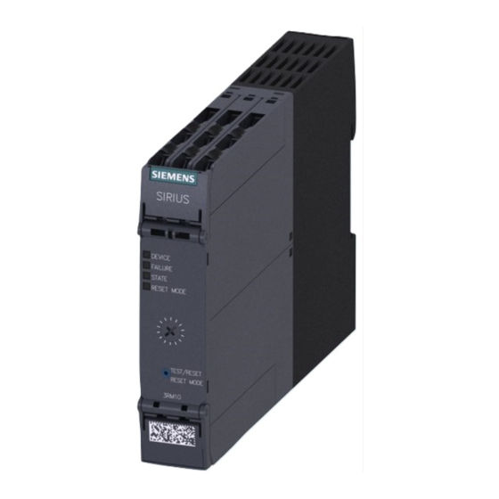
Description Overview The 3RM1 motor starter is a compact device with a width of 22.5 mm. The 3RM1 motor starter comprises combinations of relay contacts, power semiconductors, and a solid-state overload relay for switching three-phase motors up to 3 kW (at 400 V) and resistive loads up to 10 A (at AC voltages to 500 V) under normal operating conditions. -
Page 22: Applications
Description 3.2 Applications Applications The 3RM1 motor starters can be used wherever combinations of contactors and overload relays were previously used. Thanks to the additional functionality of safety-related shutdown, the 3RM11 Failsafe and 3RM13 Failsafe motor starter variants are ideally suited to safety-related applications up to SILCL 3 in accordance with EN 62061 and PL e/Cat. -
Page 23: Hybrid Technology
Description 3.3 Hybrid technology Hybrid technology The 3RM1 motor starter combines the benefits of semiconductor technology and relay technology. This combination is known as hybrid technology. The hybrid technology in the 3RM1 motor starter is characterized by the following features: Switching on The inrush current in the case of motorized loads is conducted briefly via the semiconductors. -
Page 24: Device Versions
Description 3.4 Device versions Device versions The 3RM1 motor starters are characterized by their compact design and narrow width. They can be used for easy assembly of fuseless load feeders with SIRIUS motor starter protectors. Alternatively, combinations with fuses or other short-circuit protection devices are possible. - Page 25 Description 3.4 Device versions Current ranges The 3RM1 motor starters are designed for the following rated operational currents of the loads: Versions Adjustable response value current Maximum permissible motor power at 400 V AC [kW] 3RM1.01-..0,1 ... 0,5 0,12 3RM1.02-..
- Page 26 Description 3.4 Device versions Note 3RM11/3RM13 Failsafe motor starters with 24 V DC control supply voltage The control inputs are electrically isolated from the control supply voltage (A1, A2). The terminals M1 and M2 are the reference point for the control inputs. For controlling the control inputs, e.g.
-
Page 27: Functions
Description 3.5 Functions Functions 3.5.1 Switching the 3RM1 motor starter under normal operating conditions A typical application area of the 3RM1 motor starter is the switching and protection of motors. You can also operate the 3RM1 motor starter on resistive loads such as heaters. Note Minimum loads must be observed for the 3RM1 motor starters. -
Page 28: Reversing Starter
Description 3.5 Functions 3.5.1.2 Reversing starter Using the 3RM1 motor starter as a reversing starter The 3RM12 and 3RM13 motor starters can be used as reversing starters. The reversing starter starts the motor when the control voltage is applied at input IN1 in direction of rotation 1 (no phase swapping), when controlling input IN2 in direction of rotation 2 (phase change from L1 and L3). -
Page 29: Overload Protection
Description 3.5 Functions 3.5.2 Overload protection 3.5.2.1 Protective functions Overload protection The 3RM1 motor starter protects three-phase motors against overload. If the current exceeds the set value, the 3RM1 motor starter switches off within the specified tripping time and signals the fault via the LEDs and the fault signaling output. You will find the tripping characteristic in the chapter "Overload protection/device protection characteristic (Page 125)". -
Page 30: Thermal Calculation Method (Motor Memory Module)
Description 3.5 Functions The fault state is indicated by LEDs and the fault signaling output. NOTICE Damage due to asymmetrical current consumption by built-in brakes When connecting and operating motors with built-in brakes, the energy for releasing the brakes is taken from the motor connection cables. This can result in substantial asymmetry in power consumption. - Page 31 Description 3.5 Functions If voltage is present at terminals A1/A2 and at control inputs IN1/IN2 after resetting the overload trip, the 3RM1 motor starter restarts. The rated current of 10 A must not be set for motorized loads but only for resistive loads. In this setting, the tripping characteristics deviate from Class 10A;...
-
Page 32: Atex-Certified Motor Overload Protection In The Case Of 3Rm11/3Rm13 Failsafe
Description 3.5 Functions 3.5.2.3 ATEX-certified motor overload protection in the case of 3RM11/3RM13 Failsafe Standards Increased danger in hazardous areas means it is necessary to carefully observe the following standards: ● EN 60079-14 / VDE 0165-1 Electrical apparatus for explosive gas atmospheres. ●... - Page 33 Description 3.5 Functions Control cabinet degree of protection in hazardous areas WARNING Hazardous Voltage. Can Cause Death, Serious Injury, or Property Damage. The 3RM1 motor starter is not suitable for installation in hazardous areas. The device must be installed in a control cabinet with the minimum degree of protection of IP 4x.
- Page 34 Description 3.5 Functions Short-circuit protection Short-circuit protection must be handled by separately arranged overcurrent protection devices. On this topic, refer to the Chapter "Load feeders - protection against short circuit (Page 58)". Cable protection Avoid impermissibly high cable surface temperatures by correctly dimensioning the cross sections.
-
Page 35: Shutdown On Malfunction
Description 3.5 Functions Maintenance and repairs These devices are maintenance-free. Note Repairs to the device may only be carried out by the manufacturer. Warranty NOTICE To meet the conditions of the warranty, you must observe the safety and commissioning instructions. Further information You will find further information on the Internet at ●... -
Page 36: Safety-Related Shutdown With 3Rm11/3Rm13 Failsafe Motor Starters
Description 3.5 Functions Acknowledging A malfunction is acknowledged by switching the control supply voltage back on and then pressing the "TEST/RESET/RESET MODE" pushbutton. Note If a malfunction is repeatedly indicated, the 3RM1 motor starter is defective and must be replaced. Safety-related shutdown in the case of 3RM11/3RM13 Failsafe motor starters Safety-related shutdown is achieved for the 3RM11 Failsafe and 3RM13 Failsafe motor starters thanks to the special arrangement and checking of the switching elements. - Page 37 Description 3.5 Functions In the case of 3RM11/3RM13 Failsafe motor starters, the OFF state is defined as the safe state. 3RM11/3RM13 Failsafe motor starters are self-monitoring in compliance with SILCL 3/PL e and therefore do not need to be monitored in the feedback circuit of the upstream evaluation unit/control.
- Page 38 Description 3.5 Functions Configuration with 3SK1 safety relay/fail-safe controller by means of wiring In a configuration without device connectors, the motor starters are interfaced to the 3SK1 safety relay or to the fail-safe controller and safety-related shutdown by means of wiring. If steps are taken to ensure that the cables are laid in such a way that they are protected against a cross-circuit/line-to-line fault, safety-related shutdown of A1 (L+) via a safety- related output of the control suffices.
-
Page 39: Carrying Out The Function Test
Description 3.5 Functions 3.5.5 Carrying out the function test You can start the different individual tests for the function test with the "TEST/RESET/RESET MODE" button. Procedure Depending on how long the "TEST/RESET/RESET MODE" button is pushed, a specific test is started: Actuation time for Explanation starting the test... - Page 40 Description 3.5 Functions Actuation time for Status Fault starting the test LED test < 2 s "DEVICE" LED Shows a yellow light "FAILURE" LED Shows a red light "STATE" LED Shows a green light "RESET MODE" button Shows a green light Current measuring test 2 s ...
-
Page 41: Accessories And Order Number Scheme
Description 3.6 Accessories and order number scheme Accessories and order number scheme 3.6.1 Overview of all device components ① Basic unit/expansion unit, e.g. 3RM1 motor starter ② Top cover flap ③ Bottom cover flap ④ Terminals, 3-pole, push-in, 1 x 2.5 mm² ⑤... -
Page 42: Accessories
Description 3.6 Accessories and order number scheme 3.6.2 Accessories The following accessories are offered for the 3RM1 motor starter: ● Infeed system (Page 42) ● Sealable cover (Page 44) ● Wall fixture (Page 44) ● Device connectors (Page 45) ● Terminals (Page 48) ●... - Page 43 Description 3.6 Accessories and order number scheme Table 3- 1 Order numbers of the infeed system Description Order number 3-phase busbar for two 3RM1 motor 3RM1910-1AA starters 3-phase busbar for three 3RM1 motor 3RM1910-1BA starters 3-phase busbar for five 3RM1 motor 3RM1910-1DA starters 3-phase infeed terminal...
-
Page 44: Sealable Cover
Description 3.6 Accessories and order number scheme 3.6.2.2 Sealable cover The sealable cover prevents unauthorized access to the rotary coding switch. Table 3- 2 Order number of the sealable cover Description Order number SIRIUS sealable cover 22.5 mm, cutout for pushbuttons at bottom 3ZY1321-2AA00 3.6.2.3 Wall fixture... -
Page 45: Device Connectors
Description 3.6 Accessories and order number scheme 3.6.2.4 Device connectors Function The device connectors can be used to loop through a common control supply voltage of 24 V DC to reduce wiring complexity between the individual motor starters (3RM1...-.AA04). Moreover, Failsafe motor starters with a 24 V control supply voltage (3RM11...-.AA04 / 3RM13...-.AA04) can be interfaced to one 3SK1 safety relay as a group via device connectors. - Page 46 Description 3.6 Accessories and order number scheme Using device connectors with 3SK1 safety relays Interconnection of several 3RM11/3RM13 Failsafe motor starters into a group can be used for joint safety-related shutdown by a 3SK1 safety relay. Safety-related applications up to SILCL 3 to EN 62061, PL e/Cat.
- Page 47 Description 3.6 Accessories and order number scheme Overview of all device connectors for 3RM1 motor starters and 3SK1 safety relays Order number Type of device connector Units 3ZY1212-2EA00 Device connector for 3RM1 motor 3RM1 motor starter • starters, 22.5 mm wide 3ZY1212-2FA00 Device termination connector for 3RM1 motor starter...
-
Page 48: Terminals
Description 3.6 Accessories and order number scheme 3.6.2.5 Terminals Each 3RM1 motor starter has three main current terminals and three control current terminals. The terminals can be replaced with ease. Table 3- 5 Order numbers for the terminals Description Order number ①... -
Page 49: Order Number Scheme For Sirius 3Rm1 Motor Starter
Description 3.6 Accessories and order number scheme 3.6.3 Order number scheme for SIRIUS 3RM1 motor starter Digit of the order number 1st - 3rd 10th 11th 12th ❒❒❒ ❒ ❒ ❒ ❒ ❒ ❒ ❒ ❒ ❒ SIRIUS 3RM1 motor starter Generation (1) ❒... - Page 50 Description 3.6 Accessories and order number scheme SIRIUS 3RM1 motor starter Manual, 11/2013, A5E0345285095020A/RS-AB/002...
-
Page 51: Configuration
Configuration Rated operational current and derating Values for rated operational current I Depending on the current setting range, the following rated operational currents apply for the 3RM1 motor starters: Motor starter version 3RM1.01-..3RM1.02-..3RM1.07-..Rated operational current I eAC53a Setting range for I 0,1 ... - Page 52 Configuration 4.1 Rated operational current and derating Motors with a high efficiency and high motor starting currents High starting currents may have to be taken into consideration when using 3RM1 motor starters on motors with a high efficiency (IE3 or IE4). According to the product standard IEC 60947-4-2, the 3RM1 motor starters are designed for motors with a maximum 8-fold starting current.
- Page 53 Configuration 4.1 Rated operational current and derating Motor starter version 3RM1.07-..to 7 A: For the 7 A version, the following derating values apply depending on the assembly type: Assembly type Ambient Max. setting values for 7 A device in A Side-by-side temperature for AC 53 a...
- Page 54 Configuration 4.1 Rated operational current and derating Design versions for 7 A devices For the 7 A device without clearance, a distinction is made between the following design versions: Design version Individually with clearance a = 22.5 mm Can be implemented with loop-through connectors when using device connectors.
- Page 55 Configuration 4.1 Rated operational current and derating Dependence of the rated operational current on the installation altitude The permissible rated operational current of the 3RM1 motor starter is reduced as shown in the diagram depending on the installation altitude: Note Maximum installation altitude of 3RM11/3RM13 Failsafe motor starters: 2000 m Installation altitudes of more than 2000 m are not admissible for 3RM11/3RM13 Failsafe motor starters.
-
Page 56: Ambient Conditions
Configuration 4.2 Ambient conditions Ambient conditions 4.2.1 Application environment The 3RM1 motor starters are designed for use in enclosed spaces in which no severe operating conditions prevail (e.g. dust, caustic vapors, hazardous gases). If they are to be installed in dusty or damp rooms, suitable control cabinets must be provided. -
Page 57: Permissible Operating Voltage
Configuration 4.2 Ambient conditions 4.2.5 Permissible operating voltage To be able to ensure safe isolation of the circuits from each other in accordance with IEC 60947-1, the following operating voltages are permissible: Table 4- 1 Safe isolation of the 3RM1 motor starters ... -
Page 58: Load Feeders - Protection Against Short Circuit
Configuration 4.3 Load feeders - protection against short circuit Load feeders - protection against short circuit 4.3.1 Protection against short circuit The short-circuit strength in combination with fuses is up to 100 kA at 400 V and with SIRIUS 3RV2 motor starter protectors up to 55 kA at 400 V. Type of coordination 1 is maintained here. -
Page 59: Fuseless Design
Configuration 4.3 Load feeders - protection against short circuit 4.3.3.1 Fuseless design Combining 3RM1 motor starters with motor starter protectors DANGER Hazardous Voltage at the Motor Can Cause Death, Serious Injury, or Property Damage. Health hazard from automatic hot restart. The safety function must be checked after every tripping of the motor starter protector (also in the case of overload). - Page 60 Configuration 4.3 Load feeders - protection against short circuit Combining 3RM1 motor starters with miniature circuit breakers DANGER Hazardous Voltage at the Motor Can Cause Death, Serious Injury, or Property Damage. Health hazard from automatic hot restart. The safety function must be checked after every tripping of the motor starter protector (also in the case of overload).
-
Page 61: Fused Design
Configuration 4.3 Load feeders - protection against short circuit 4.3.3.2 Fused design Combining 3RM1 motor starters with fuses DANGER Hazardous Voltage at the Motor Can Cause Death, Serious Injury, or Property Damage. Health hazard from automatic hot restart. The safety function must be checked after every tripping of the motor starter protector (also in the case of overload). -
Page 62: Configuration Of A Load Feeder With 3Rm1 Motor Starter In Compliance With Ul
Configuration 4.3 Load feeders - protection against short circuit 4.3.4 Configuration of a load feeder with 3RM1 motor starter in compliance with UL 4.3.4.1 Function according to UL 508 The 3RM1 motor starters can be combined individually with a circuit breaker (motor starter protector) or fuses. -
Page 63: Fuses And Circuit Breakers
Configuration 4.3 Load feeders - protection against short circuit 4.3.4.3 Fuses and circuit breakers Fuse data for motor starters DANGER Hazardous Voltage. Can Cause Death, Serious Injury, or Property Damage. Health hazard from automatic hot restart. The 3RM1 motor starter and the safety function must be checked after every tripping of the motor starter protector (also in the case of overload). -
Page 64: Infeed For The Main Circuit
Configuration 4.4 Infeed for the main circuit Circuit breakers for protecting against short-circuit currents DANGER Hazardous Voltage. Can Cause Death, Serious Injury, or Property Damage. Health hazard from automatic hot restart. The 3RM1 motor starter and the safety function must be checked after every tripping of the motor starter protector (also in the case of overload). -
Page 65: 3Rm19 3-Phase Infeed System
Configuration 4.4 Infeed for the main circuit 4.4.2 3RM19 3-phase infeed system The 3RM19 3-phase infeed system is designed for 3RM1...-1AA.4 motor starters with screw connections and 3RM1...-3AA.4 motor starters with hybrid connections. Push-in terminals can therefore not be connected with this infeed system. Note Use of several busbars More than five devices can be connected by clamping the terminal lugs of a second busbar... - Page 66 Configuration 4.4 Infeed for the main circuit Mounting Attach the busbar from below to the rear terminals L1, L2 and L3 of the 3RM1 motor starter. The outgoing feeders to the motors thus remain accessible. Figure 4-1 Attaching the 3RM19 infeed system to the 3RM1 motor starters DANGER Hazardous Voltage.
-
Page 67: Configuration With Device Connectors
Configuration 4.5 Configuration with device connectors Configuration with device connectors 4.5.1 Configuration with device connectors The device connector may be used only with the 24 V DC version of the motor starter. There must be no mixing of the Standard and Failsafe variants of the 3RM1 motor starter via the device connector. - Page 68 Configuration 4.6 Examples/applications Basic configuration ① ① ④ Instead of the black box, one of the modules can be used ④ ① SIRIUS 3TK28 safety relay ② SIRIUS 3SK1 safety relay ③ SIMATIC S7 fail-safe modules ④ SIRIUS 3RK3 modular safety system ⑤...
- Page 69 Configuration 4.6 Examples/applications When the EMERGENCY-STOP is actuated, the motor starters' control supply voltage is shut down and the motor is isolated from the power supply. Due to the internal self-monitoring of the 3RM11/13 Failsafe motor starters in compliance with SILCL 3/PL e, there is no need for a feedback signal to the 3SK1 safety relay.
- Page 70 Configuration 4.6 Examples/applications ① SIRIUS 3SK1 Advanced basic unit ② SIRIUS 3RM1 Failsafe (3RM11 Failsafe or 3RM13 Failsafe) safety-related motor starters ③ SIRIUS 3RV2 motor starter protector ④ EMERGENCY-STOP button ⑤ Motor Figure 4-3 Configuration with 3SK1 safety relay and device connectors Note No hybrid operation of Failsafe and Standard 3RM1 motor starters Hybrid operation of 3RM11/3RM13 Failsafe motor starters with 3RM10/3RM12 Standard...
-
Page 71: Mounting
Mounting Warning notices Warning notices before installation, wiring, and commissioning DANGER Hazardous Voltage. Can Cause Death, Serious Injury, or Property Damage. Hazardous electrical voltage can cause electric shock, burns and damage. Turn off and lock out all power supplying this device before working on the device. SIRIUS 3RM1 motor starter Manual, 11/2013, A5E0345285095020A/RS-AB/002... -
Page 72: Mounting The Devices On A Level Surface
Mounting 5.2 Mounting the devices on a level surface Mounting the devices on a level surface Requirements Please note the following requirements for mounting on a level surface: ● Please observe the information about the mounting position in the chapter "Mounting position (Page 56)". -
Page 73: Disassembling The Devices From A Level Surface
Mounting 5.3 Disassembling the devices from a level surface Disassembling the devices from a level surface WARNING Hazardous Voltage. Can Cause Death, Serious Injury, or Property Damage. Turn off and lock out all power supplying this device before working on this device. Requirements ●... -
Page 74: Mounting The Devices On A Standard Mounting Rail
Mounting 5.4 Mounting the devices on a standard mounting rail Mounting the devices on a standard mounting rail Requirements ● At the installation location, a horizontal 35 mm mounting rail in accordance with DIN EN 60715 is properly secured ● Please observe the information about the mounting position in chapter "Mounting position (Page 56)"... -
Page 75: Disassembling Devices From A Standard Mounting Rail
Mounting 5.5 Disassembling devices from a standard mounting rail Disassembling devices from a standard mounting rail WARNING Hazardous Voltage. Can Cause Death, Serious Injury, or Property Damage. Turn off and lock out all power supplying this device before working on this device. Requirements ●... -
Page 76: Mounting The Devices With Device Connectors On A Standard Mounting Rail
Mounting 5.6 Mounting the devices with device connectors on a standard mounting rail Mounting the devices with device connectors on a standard mounting rail Requirements ● At the installation location, a horizontal 35 mm mounting rail in accordance with DIN EN 60715 is properly secured ●... - Page 77 Mounting 5.6 Mounting the devices with device connectors on a standard mounting rail Step Operating instruction Figure Mount the device on the device connector. Mount all the devices required for the system configuration in accordance with the respective installation guidelines on the device connectors.
-
Page 78: Disassembling The Devices With Device Connectors From A Standard Mounting Rail
Mounting 5.7 Disassembling the devices with device connectors from a standard mounting rail Disassembling the devices with device connectors from a standard mounting rail WARNING Hazardous Voltage. Can Cause Death, Serious Injury, or Property Damage. Turn off and lock out all power supplying this device before working on this device. Requirements ●... - Page 79 Mounting 5.7 Disassembling the devices with device connectors from a standard mounting rail Step Operating instruction Figure Pull the device away from the device connector. Separate the device connectors using a screwdriver. Remove the cover to the left of the first device connector.
- Page 80 Mounting 5.7 Disassembling the devices with device connectors from a standard mounting rail Step Operating instruction Figure Press the device connector down. Pull the lower half of the device connector away from the standard mounting rail. Lift the device connector from the upper edge of the standard mounting rail.
-
Page 81: Mounting The Devices With Device Connectors On A Wall
Mounting 5.8 Mounting the devices with device connectors on a wall Mounting the devices with device connectors on a wall Requirements Please note the following requirements for mounting on a level surface: ● Please observe the information about the mounting position in the chapter "Mounting position (Page 56)". - Page 82 Mounting 5.8 Mounting the devices with device connectors on a wall Step Operating instruction Figure Hold the device connector against the level surface prepared for screw fastening. Insert the screws through the holes in the device connectors. Screw the device connector securely onto the level surface.
-
Page 83: Disassembling The Devices With Device Connectors From A Wall
Mounting 5.9 Disassembling the devices with device connectors from a wall Disassembling the devices with device connectors from a wall WARNING Hazardous Voltage. Can Cause Death, Serious Injury, or Property Damage. Turn off and lock out all power supplying this device before working on this device. Requirements ●... - Page 84 Mounting 5.9 Disassembling the devices with device connectors from a wall Step Operating instruction Figure Pull the device away from the device connector. Release the screws. Separate the device connectors using a screwdriver. Remove the cover to the left of the first device connector.
-
Page 85: Mounting The Sealable Cover
Mounting 5.10 Mounting the sealable cover 5.10 Mounting the sealable cover The sealable cover is used to protect the set rated operational current of the load (current setting I ) against unauthorized or unintentional manipulation. Procedure Step Operating instruction Figure Attach the two bottom hooks on the cover to the openings on the device and fold the cover up... - Page 86 Mounting 5.10 Mounting the sealable cover SIRIUS 3RM1 motor starter Manual, 11/2013, A5E0345285095020A/RS-AB/002...
-
Page 87: Connection
Connection Connecting the screw-type terminals WARNING Hazardous Voltage. Can Cause Death, Serious Injury, or Property Damage. Turn off and lock out all power supplying this device before working on this device. NOTICE Absence of overvoltage protection if wiring is wrong Observe the wiring's terminal assignments: For optimum response in the event of short circuits and for protection against overvoltages, the main circuit's infeed must be at terminals 1/L1 to 5/L3. - Page 88 Connection 6.1 Connecting the screw-type terminals Step Operating instruction Figure Insert the relevant cable into square on the screw terminal until it engages. Hold the cable in the screw terminal. Tighten the screw with a torque of 0.6 to 0.8 Nm. Pull on the cable to ensure it is screwed tight.
-
Page 89: Disconnecting The Screw-Type Terminals
Connection 6.2 Disconnecting the screw-type terminals Disconnecting the screw-type terminals WARNING Hazardous Voltage. Can Cause Death, Serious Injury, or Property Damage. Turn off and lock out all power supplying this device before working on this device. Requirements ● Cross-tip screwdriver size PZ 1 x 80 Procedure Step Operating instruction... -
Page 90: Connecting The Push-In Terminals
Connection 6.3 Connecting the push-in terminals Connecting the push-in terminals 6.3.1 Wiring rules for spring-loaded terminals (with push-in technology) Wiring rules for ... Control current terminals (top of Main current terminals enclosure): (bottom of enclosure) Connectable cross-sections for solid cables 2 x 0.5 ... -
Page 91: Connecting The Push-In Terminals
Connection 6.3 Connecting the push-in terminals Control current terminals Main current terminals Terminal area of main current terminals Terminal area of control current terminals 6.3.2 Connecting the push-in terminals WARNING Hazardous Voltage. Can Cause Death, Serious Injury, or Property Damage. Turn off and lock out all power supplying this device before working on this device. - Page 92 Connection 6.3 Connecting the push-in terminals Procedure Table 6- 1 Rigid conductors or conductors equipped with end sleeves Step Operating instruction Figure Insert the cable into the oval opening as far as it will go. Pull on the cable to ensure it is tight. Table 6- 2 Finely-stranded conductors Step...
-
Page 93: Disconnecting The Push-In Terminals
Connection 6.4 Disconnecting the push-in terminals Disconnecting the push-in terminals WARNING Hazardous Voltage. Can Cause Death, Serious Injury, or Property Damage. Turn off and lock out all power supplying this device before working on this device. Requirements ● Screwdriver DIN 5264 of the size 0.5 x 3 mm Procedure Step Operating instruction... -
Page 94: Attaching The Terminals
Connection 6.5 Attaching the terminals Attaching the terminals WARNING Hazardous Voltage. Can Cause Death, Serious Injury, or Property Damage. Turn off and lock out all power supplying this device before working on this device. Requirements ● You must have removed the terminals, for the purpose of replacing a device, for example. Procedure Step Operating instruction... -
Page 95: Removing The Terminals
Connection 6.6 Removing the terminals Removing the terminals WARNING Hazardous Voltage. Can Cause Death, Serious Injury, or Property Damage. Turn off and lock out all power supplying this device before working on this device. Procedure Step Operating instruction Figure Press the clip of the terminal block upwards. Pull the terminal out to the front. -
Page 96: Connecting The Infeed System (Option)
Connection 6.7 Connecting the infeed system (option) Connecting the infeed system (option) WARNING Hazardous Voltage. Can Cause Death, Serious Injury, or Property Damage. Turn off and lock out all power supplying this device before working on this device. Requirements Please note the following requirements for mounting the 3RM19 infeed system: ●... - Page 97 Connection 6.7 Connecting the infeed system (option) Procedure Figure 6-1 Mount the 3RM19 infeed system DANGER Hazardous Voltage. Can Cause Death, Serious Injury, or Property Damage. If free and uncovered terminal lugs are touched when the load voltage is switched on, death or serious injury can result.
- Page 98 Connection 6.7 Connecting the infeed system (option) Step Operating instruction Connect the main circuit L1, L2 and L3 to the infeed terminal. Tighten the screw terminals with 0.6 to 0.8 Nm. Pull on the cables to ensure they are screwed tight. Plug the first busbar into the rear screw terminals on the underside of the device.
-
Page 99: Operator Control And Monitoring
Operator control and monitoring Operator controls The following operator controls are available on the 3RM1 motor starter for parameter assignment and operation: ● Rotary coding switch with adjusting scale for current setting "I ": You set the rated operational current of the load "I "... -
Page 100: Parameterizing The 3Rm1 Motor Starter
Operator control and monitoring 7.1 Operator controls 7.1.1 Parameterizing the 3RM1 motor starter All the settings are made directly at the 3RM1 motor starter: ① Rotary coding switch for rated operational current of the load ② TEST/RESET/RESET MODE button Figure 7-1 Front view of the 3RM1 motor starter 7.1.2 Setting the rated operational current... - Page 101 Operator control and monitoring 7.1 Operator controls Manual RESET After an overload trip, reset the 3RM1 motor starter manually after a cooling time of three minutes using the "TEST/RESET/RESET MODE" button. As an alternative, in the case of the 3RM10/3RM12 standard motor starters, you can use the RESET control input IN3 for acknowledgement.
- Page 102 Operator control and monitoring 7.1 Operator controls Note Briefly switching the supply voltage off and on again does not shorten the cooling time and there is no automatic acknowledgement. SIRIUS 3RM1 motor starter Manual, 11/2013, A5E0345285095020A/RS-AB/002...
-
Page 103: Displays And Location Of The Connections
Operator control and monitoring 7.2 Displays and location of the connections Displays and location of the connections ① LED DEVICE (red/green/yellow) ② LED FAILURE (red) ③ LED STATE (green) ④ LED RESET MODE (green) ⑤ Rotary coding switch for the rated operational current "I "... - Page 104 Operator control and monitoring 7.2 Displays and location of the connections Location of the connections The terminal covers for the control and main circuit are labeled on the inside with the designations of the relevant terminals. The position of the label corresponds to the position of the respective terminal.
- Page 105 Operator control and monitoring 7.2 Displays and location of the connections Terminal cover Depending on the version of the 3RM1 motor starter, the device will have the following connections: Motor starter version Inscription of the terminal cover Control circuit (at the top of the device) Standard 24 V DC •...
-
Page 106: Alarms, Faults And System Events
Operator control and monitoring 7.2 Displays and location of the connections 7.2.1 Alarms, faults and system events 7.2.1.1 LEDs The 3RM1 motor starter provides device status information via four LEDs: Displayable colors DEVICE Red/green/yellow FAILURE STATE Green RESET MODE Green 7.2.1.2 Status indicators of the 3RM1 motor starter The 3RM1 motor starter indicates the status messages for operation, fault and test via the... - Page 107 Operator control and monitoring 7.2 Displays and location of the connections Fault Fault Reaction of Possible cause/corrective measure signaling feedback DEVICE FAILURE STATE RESET output circuit MODE Yellow Green/off* Active Overload trip motor protection • Motor blocks during starting or operation •...
-
Page 108: Signaling Faults On External I/O
Operator control and monitoring 7.2 Displays and location of the connections 7.2.1.3 Signaling faults on external I/O Fault signaling output Faults are signaled via relay outputs as well as via the LEDs. In the event of a fault, contact (95-98) closes and contact (95-96) opens. The faults that result in pick-up of the relays are listed in the chapter "Status indicators of the 3RM1 motor starter (Page 106)". - Page 109 Operator control and monitoring 7.2 Displays and location of the connections Other faults You acknowledge all other faults using the "TEST/RESET/RESET MODE" button. As an alternative, in the case of the 3RM10/3RM12 Standard motor starters, you can use the RESET control input IN3 for acknowledgement. You will find information about setting the reset method in the chapter Setting the RESET method (Page 100).
- Page 110 Operator control and monitoring 7.2 Displays and location of the connections SIRIUS 3RM1 motor starter Manual, 11/2013, A5E0345285095020A/RS-AB/002...
-
Page 111: Service And Maintenance
Service and maintenance Maintenance and service The 3RM1 motor starters are maintenance-free. The motor starter indicates a detected malfunction with LEDs and the fault output. Note If a malfunction is repeatedly indicated, the 3RM1 motor starter is defective and must be replaced. -
Page 112: Device Replacement
Service and maintenance 8.2 Device replacement Device replacement WARNING Hazardous Voltage. Can Cause Death, Serious Injury, or Property Damage. Turn off and lock out all power supplying this device before working on this device. When replacing a device, you do not need to re-wire it. The terminals can be disconnected from the defective device and then connected to the new device. -
Page 113: Technical Data
Technical data Motor starters 9.1.1 General technical specifications 3RM10..-..3RM11..-..3RM12..-..3RM13..-..22.5 Width • Height • 141.6 Depth • Ambient temperature °C -25 … +60 during operating • °C -40 … +70 during storage • °C -40 … +70 during transport •... - Page 114 Technical data 9.1 Motor starters 3RM10..-..3RM11..-..3RM12..-..3RM13..-..Distance, to be maintained, to the ranks assembly downwards • upwards • backwards • sidewards • forwards • Distance, to be maintained, to earthed part downwards • upwards • backwards • sidewards •...
-
Page 115: Electromagnetic Compatibility (Emc)
Technical data 9.1 Motor starters 9.1.2 Electromagnetic compatibility (EMC) Emitted interference Emitted interference depends on the rated control supply voltage. Rated control supply voltage Order number 24 V DC 3RM1...-...0. 110 ... 230 V AC/110 V DC 3RM1...-...1. 3RM1...-...0. 3RM1...-...1. Class B for the domestic, Class B for domestic, business Conductor-bound HF-interference... - Page 116 Technical data 9.1 Motor starters Interference immunity of the 3RM11 and 3RM13 Failsafe motor starters 3RM11..-..3RM13..-..6 kV contact discharge / 8 kV air discharge Electrostatic discharge according to IEC 61000-4-2 • 10 V Conducted interference as high-frequency radiation •...
-
Page 117: Control Circuit
Technical data 9.1 Motor starters 9.1.3 Control circuit The technical data of the control circuit depends on the control supply voltage. Rated control supply voltage Order number 24 V DC 3RM1...-.AA0. 110 ... 230 V AC/110 V DC 3RM1...-.AA1. A distinction is made in the two tables between the 3RM10/3RM12 Standard motor starters and the 3RM11/3RM13 Failsafe motor starters. - Page 118 Technical data 9.1 Motor starters 3RM11/3RM13 Failsafe motor starters 3RM11..-.AA0. 3RM13..-.AA0. 3RM11..-.AA1. 3RM13..-.AA1. Type of voltage AC/DC Control supply voltage 1 110 … 230 at 50 Hz for AC • 110 … 230 at 60 Hz for AC • for DC •...
- Page 119 Technical data 9.1 Motor starters Note 3RM10/3RM12 Standard motor starters with 110 to 230 V AC/110 V DC control supply voltage The same voltage source (potential) must be used for the control supply voltage and the control inputs. The reference point for the control inputs is terminal A2. When controlling with a PLC, control must be via relay outputs.
-
Page 120: Main Circuit
Technical data 9.1 Motor starters 9.1.4 Main circuit The technical data of the main circuit depends on the adjustable rated motor current. Adjustable rated motor current Order number 0.1 ... 0.5 A 3RM1.01-..0.4 ... 2.0 A 3RM1.02-..1.6 ... 7.0 A 3RM1.07-.. -
Page 121: Safety Data
Technical data 9.1 Motor starters 9.1.5 Safety data 9.1.5.1 General safety data The 3RM11 Failsafe motor starters (direct-on-line starters) / 3RM13 Failsafe motor starters (reversing starters) have the following safety data: 3RM11..-..3RM13..-..Safety Integrity Level (SIL) according to IEC 61508 SIL3 Performance level (PL) according to ISO 13849-1 Category according to ISO 13849-1... -
Page 122: Atex-Specific Safety Data
Technical data 9.1 Motor starters 9.1.5.2 ATEX-specific safety data Referred to ATEX, the 3RM11 Failsafe motor starters (direct-on-line starters) / 3RM13 Failsafe motor starters (reversing starters) have the following safety data: Safety integrity level (SILCL) Hardware fault tolerance (HFT) Interval for testing the protective functions 3 years Probability of failure on demand (PFD) 5x10... -
Page 123: Connection Cross Sections
Technical data 9.1 Motor starters 9.1.6 Connection cross sections Connectable cable cross-sections depend on the motor starter's connection system. Connection system Order number Screw connection 3RM1...-1AA.4 Push-in spring-type terminals 3RM1...-2AA.4 Hybrid connection method 3RM1...-3AA.4 Control circuit realized as push-in spring-loaded terminal and main circuit as screw terminal The table below contains the suitable conductor cross-sections for the control circuit and signaling contacts (= auxiliary contacts) and for the main circuit (= main contacts). -
Page 124: Number Of Starting Operations
Technical data 9.1 Motor starters 9.1.7 Number of starting operations Permissible number of starting operations per hour 1/h Parameter: on-load factor = 50 % The number of starting operations 1/h is calculated for an effective motor current of 100 %, and the motor starter's actual performance can be higher. -
Page 125: Overload Protection/Device Protection Characteristic
Technical data 9.1 Motor starters 9.1.8 Overload protection/device protection characteristic Overload protection Figure 9-1 Motor overload protection characteristic Device protection against overload trips at current setting values from 4.6 A. This results in shorter tripping times; see figure below. SIRIUS 3RM1 motor starter Manual, 11/2013, A5E0345285095020A/RS-AB/002... - Page 126 Technical data 9.1 Motor starters Equipment protection In addition to the motor protection function, the 3RM1 motor starters also protect themselves against overload. This means that in the case of 3RM1 motor starters with a rated operational current of 7 A, an overload trip may occur in the upper current range before the motor protection trips.
- Page 127 Technical data 9.1 Motor starters Resistive loads The tripping characteristic shown does not apply for resistive loads at a setting value of 10 A. In this case, tripping takes place as follows: Tripping after 10 A < load current < 15 A 20 s Load current >...
-
Page 128: Infeed System For 3Rm1 Motor Starter
Technical data 9.2 Infeed system for 3RM1 motor starter Infeed system for 3RM1 motor starter 9.2.1 General technical data Infeed system 3RM1910-1AA 3RM1910-1BA 3RM1910-1DA product designation Busbar 2x Busbar 3x Busbar 5x Design of the product for 2 starters for 3 starters for 5 starters Height Width... -
Page 129: Dimension Drawings
Dimension drawings 10.1 3RM1 dimension drawings Dimension drawing for 3RM1 motor starter SIRIUS 3RM1 motor starter Manual, 11/2013, A5E0345285095020A/RS-AB/002... - Page 130 Dimension drawings 10.1 3RM1 dimension drawings Drilling diagram for push-in lugs for wall mounting SIRIUS 3RM1 motor starter Manual, 11/2013, A5E0345285095020A/RS-AB/002...
- Page 131 Dimension drawings 10.1 3RM1 dimension drawings Dimension drawing for 3RM1 motor starter with infeed terminal and system SIRIUS 3RM1 motor starter Manual, 11/2013, A5E0345285095020A/RS-AB/002...
-
Page 132: Dimension Drawings For 3Rm1 Device Connectors
Dimension drawings 10.2 Dimension drawings for 3RM1 device connectors 10.2 Dimension drawings for 3RM1 device connectors Dimension drawing of device connectors for 3RM1 motor starter SIRIUS 3RM1 motor starter Manual, 11/2013, A5E0345285095020A/RS-AB/002... - Page 133 Dimension drawings 10.2 Dimension drawings for 3RM1 device connectors Dimension drawing of device termination connectors for 3RM1 motor starter SIRIUS 3RM1 motor starter Manual, 11/2013, A5E0345285095020A/RS-AB/002...
- Page 134 Dimension drawings 10.2 Dimension drawings for 3RM1 device connectors Dimension drawing of device connectors for signal loop-through SIRIUS 3RM1 motor starter Manual, 11/2013, A5E0345285095020A/RS-AB/002...
- Page 135 Dimension drawings 10.2 Dimension drawings for 3RM1 device connectors Drilling diagram for device connectors with 22 mm width SIRIUS 3RM1 motor starter Manual, 11/2013, A5E0345285095020A/RS-AB/002...
- Page 136 Dimension drawings 10.2 Dimension drawings for 3RM1 device connectors SIRIUS 3RM1 motor starter Manual, 11/2013, A5E0345285095020A/RS-AB/002...
-
Page 137: Circuit Diagrams
Circuit diagrams 11.1 3RM10 circuit diagrams (direct-on-line starter, Standard) Versions with 24 V DC control supply voltage SIRIUS 3RM1 motor starter Manual, 11/2013, A5E0345285095020A/RS-AB/002... - Page 138 Circuit diagrams 11.1 3RM10 circuit diagrams (direct-on-line starter, Standard) Versions with 110 … 230 V AC; 110 V DC control supply voltage Note Parallel loads in the case of motor starters with product version E01 In the case of motor starters with product version E01, no parallel loads can be connected to the IN terminal;...
-
Page 139: 3Rm11 Circuit Diagrams (Direct-On-Line Starter, Failsafe)
Circuit diagrams 11.2 3RM11 circuit diagrams (direct-on-line starter, Failsafe) 11.2 3RM11 circuit diagrams (direct-on-line starter, Failsafe) Versions with 24 V DC control supply voltage Versions with 110 … 230 V AC; 110 V DC control supply voltage SIRIUS 3RM1 motor starter Manual, 11/2013, A5E0345285095020A/RS-AB/002... -
Page 140: 3Rm12 Circuit Diagrams (Reversing Starter, Standard)
Circuit diagrams 11.3 3RM12 circuit diagrams (reversing starter, Standard) 11.3 3RM12 circuit diagrams (reversing starter, Standard) Versions with 24 V DC control supply voltage Versions with 110 … 230 V AC; 110 V DC control supply voltage SIRIUS 3RM1 motor starter Manual, 11/2013, A5E0345285095020A/RS-AB/002... - Page 141 Circuit diagrams 11.3 3RM12 circuit diagrams (reversing starter, Standard) Note Parallel loads in the case of motor starters with product version E01 In the case of motor starters with product version E01, no parallel loads can be connected to the IN terminal; see diagram below. This is admissible as of product version E02. SIRIUS 3RM1 motor starter Manual, 11/2013, A5E0345285095020A/RS-AB/002...
-
Page 142: 3Rm13 Circuit Diagrams (Reversing Starter, Failsafe)
Circuit diagrams 11.4 3RM13 circuit diagrams (reversing starter, Failsafe) 11.4 3RM13 circuit diagrams (reversing starter, Failsafe) Versions with 24 V DC control supply voltage Versions with 110 … 230 V AC; 110 V DC control supply voltage SIRIUS 3RM1 motor starter Manual, 11/2013, A5E0345285095020A/RS-AB/002... -
Page 143: Typical Circuits
Typical circuits Typical circuits for 3RM1 Standard A.1.1 Direct-on-line starter 24 V DC with switch operation The 3RM1 motor starter is controlled with a switch. The 3RM1 motor starter is operated as a direct-on-line starter. Remote reset Figure A-1 Direct-on-line starter 24 V DC with switch operation SIRIUS 3RM1 motor starter Manual, 11/2013, A5E0345285095020A/RS-AB/002... -
Page 144: Direct-On-Line Starter 24 V Dc With Switch Operation And 230 V Brake
Typical circuits A.1 Typical circuits for 3RM1 Standard A.1.2 Direct-on-line starter 24 V DC with switch operation and 230 V brake The current for the brake facility is drawn via only one phase. Connection is via T2. Note This operating mode is not suitable for 3RM11 Failsafe and 3RM13 Failsafe motor starters since there is a connection to the neutral conductor. -
Page 145: Direct-On-Line Starter 24 V Dc With Switch Operation And 400 V Brake
Typical circuits A.1 Typical circuits for 3RM1 Standard A.1.3 Direct-on-line starter 24 V DC with switch operation and 400 V brake The current for the brake facility is drawn via two phases. Connection is via T1 and T3. Make allowance for the additional current in the current setting value. Remote reset Figure A-3 Direct-on-line starter 24 V DC with switch operation and 400 V brake... -
Page 146: Direct-On-Line Starter 24 V Dc With Switch Operation And Single-Phase Motor
Typical circuits A.1 Typical circuits for 3RM1 Standard A.1.4 Direct-on-line starter 24 V DC with switch operation and single-phase motor The current is drawn via only one phase. The motor is connected at T3. The second connection is directly at the neutral conductor. On the 3RM1 motor starter, T1 is wired direct with T2, and L2 direct with L3. - Page 147 Typical circuits A.1 Typical circuits for 3RM1 Standard Remote reset Figure A-4 Direct-on-line starter 24 V DC with switch operation and single-phase motor SIRIUS 3RM1 motor starter Manual, 11/2013, A5E0345285095020A/RS-AB/002...
-
Page 148: Direct-On-Line Starter With Group Protection, 24 V Dc And Plc Operation
Typical circuits A.1 Typical circuits for 3RM1 Standard A.1.5 Direct-on-line starter with group protection, 24 V DC and PLC operation Several 3RM1 motor starters can be connected by means of 3-phase busbars on the main current side. Control takes place via digital outputs. Figure A-5 Direct-on-line starter with group protection, 24 V DC and PLC operation SIRIUS 3RM1 motor starter... -
Page 149: Reversing Starter 24 V Dc With Plc Operation
Typical circuits A.1 Typical circuits for 3RM1 Standard A.1.6 Reversing starter 24 V DC with PLC operation The motor is controlled via a PLC. The 3RM1 motor starter is operated as a reversing starter. Figure A-6 Reversing starter 24 V DC with PLC operation SIRIUS 3RM1 motor starter Manual, 11/2013, A5E0345285095020A/RS-AB/002... -
Page 150: Typical Circuits For 3Rm1 Failsafe
Typical circuits A.2 Typical circuits for 3RM1 Failsafe Typical circuits for 3RM1 Failsafe A.2.1 General safety notes Note SILCL 3 in accordance with EN 62061/PL e in accordance with EN ISO 13849-1 The 3RM11/3RM13 motor starters are designed in such a way as to allow implementation of applications up to SILCL 3 in accordance with EN 62061 and PL e/Cat. - Page 151 Typical circuits A.2 Typical circuits for 3RM1 Failsafe WARNING Function test interval for 3RM11/3RM13 Failsafe motor starters In continuous operation, the key safety values apply in the case of a function test interval (state change of the outputs) ≤ 1 year. Annual function test •...
- Page 152 Typical circuits A.2 Typical circuits for 3RM1 Failsafe WARNING Protection against electrically conductive contamination! The devices must be protected against conductive contamination while taking account of the ambient conditions. One way you can do this is to install the devices in a control cabinet with the appropriate degree of protection.
-
Page 153: 3Sk1 Safety Relay With 3Rm13 Motor Starter Via Device Connector
Typical circuits A.2 Typical circuits for 3RM1 Failsafe A.2.2 3SK1 safety relay with 3RM13 motor starter via device connector The 3RM13 Failsafe motor starter is connected to a 3SK1 safety relay via a 3ZY1 device connector. The two directions of rotation are switched on and off operationally via IN1 and IN2, e.g. with a PLC. - Page 154 Typical circuits A.2 Typical circuits for 3RM1 Failsafe If there is a common reference potential for the two inputs, it suffices to establish a ground connection. If there are separate potentials or controls, both connections must be assigned. Figure A-7 3SK1 safety relay with 3RM13 reversing starter via device connector SIRIUS 3RM1 motor starter Manual, 11/2013, A5E0345285095020A/RS-AB/002...
-
Page 155: 3Sk1 Safety Relay Wired With 3Rm13 Motor Starter
Typical circuits A.2 Typical circuits for 3RM1 Failsafe A.2.3 3SK1 safety relay wired with 3RM13 motor starter The 3RM13 Failsafe motor starter (230 V supply voltage) is connected to a 3SK1 safety relay. The two directions of rotation are switched on and off operationally via IN1 and IN2, e.g. with separate switches. - Page 156 Typical circuits A.2 Typical circuits for 3RM1 Failsafe Figure A-8 3SK1 safety relay with 3RM13 reversing starter SIRIUS 3RM1 motor starter Manual, 11/2013, A5E0345285095020A/RS-AB/002...
-
Page 157: 3Rm13 Reversing Starter With Plc Control, F-Do Pp-Switching
Typical circuits A.2 Typical circuits for 3RM1 Failsafe A.2.4 3RM13 reversing starter with PLC control, F-DO pp-switching As an alternative to the 3SK1 safety relay, 3RM11/3RM13 Failsafe motor starters can be controlled by an F-DO module. In this typical circuit, shutdown is realized by a pp-switching F-DO module in 1 channel. - Page 158 Typical circuits A.2 Typical circuits for 3RM1 Failsafe Figure A-9 3RM13 reversing starter with PLC control, F-DO pp-switching SIRIUS 3RM1 motor starter Manual, 11/2013, A5E0345285095020A/RS-AB/002...
-
Page 159: 3Rm13 Reversing Starter With Plc Control, F-Do Pm-Switching
Typical circuits A.2 Typical circuits for 3RM1 Failsafe A.2.5 3RM13 reversing starter with PLC control, F-DO pm-switching As an alternative to the 3SK1 safety relay, 3RM11/3RM13 Failsafe motor starters can be controlled by an F-DO module. In this typical circuit, shutdown is realized by a pm-switching F-DO module in 2 channels. - Page 160 Typical circuits A.2 Typical circuits for 3RM1 Failsafe SIRIUS 3RM1 motor starter Manual, 11/2013, A5E0345285095020A/RS-AB/002...
-
Page 161: Directives
Directives ESD Guidelines Definition of ESD All electronic modules are equipped with large-scale integrated ICs or components. Due to their design, these electronic elements are highly sensitive to overvoltage, and thus to any electrostatic discharge. The electrostatic sensitive components/modules are commonly referred to as ESD devices. This is also the international abbreviation for such devices. - Page 162 Directives B.1 ESD Guidelines Electrostatic charging Anyone who is not connected to the electrical potential of their surroundings can be electrostatically charged. The figure below shows the maximum electrostatic voltage which may build up on a person coming into contact with the materials indicated. These values correspond to IEC 801-2 specifications.
-
Page 163: Correction Sheet
Correction sheet Have you noticed any errors while reading this manual? If so, please use this form to tell us about them. We welcome comments and suggestions for improvement. Fax response From (please complete): Name SIEMENS AG I IA CE MK&ST 3 Company/Department 92220 Amberg / Germany Address... - Page 164 Correction sheet SIRIUS 3RM1 motor starter Manual, 11/2013, A5E0345285095020A/RS-AB/002...
-
Page 165: Glossary
Glossary 3-phase busbar The 3-phase busbar enables several 3RM1 motor starters to be supplied using a single infeed terminal. Approval Approval of switching devices and switchgear in accordance with national standards, some of which must be met on a mandatory basis, which exist in addition to "IEC", "CENELEC", and "CEE"... - Page 166 Glossary Main switch Every industrial machine which falls under the scope of DIN EN 60204 Part 1 (VDE 0113, Part 1) must be equipped with a main switch which disconnects all electrical equipment from the network while cleaning, maintenance, and repair work is being carried out, as well as during long periods of downtime.
- Page 167 Glossary Push-in lugs for wall mounting The adapters for screw mounting enable the 3RM1 motor starter to be mounted on a level surface. Rated conditional short-circuit current I The assured short-circuit breaking capacity of switchgear assemblies and load feeders, also called "rated conditional short-circuit current".
- Page 168 Glossary Trip class (CLASS) The trip class of an inverse time-delay overload relay specifies the maximum tripping time from cold at a particular load. The trip class number (e.g. CLASS 10A) represents the maximum permissible tripping time in seconds when the 3RM1 motor starter is subjected to a symmetrical 3-pole load from cold with 7.2 times the current setting (IEC 60947-4-1;...
-
Page 169: Index
Index CLASS 10A, 51, 127 Configuration, 13 Configurator, 13 Conformity, 10 2D dimensional drawings, 12 Connecting, 30 Connection, 104 Connection system, 24 Connections, 105 3D models, 12 Control circuit, 103 Control current terminal, 90 3-phase busbar, 42 3-phase infeed terminal, 43 Control current terminals, 48 3SK1 safety relay, 11, 37, 46, 68 Control input, 28... - Page 170 Index Examples, 11 Main circuit, 64, 103 Main current terminal, 90 Main current terminals, 48 Fail-safe controller, 38 Maintenance, 35, 111 FAQs, 12 Malfunction, 35, 108, 111 Fault, 107 Display concept, 36 Fault rectification, 109 Manual RESET, 101 Fault signaling output, 103, 108 Messages, 106 Feedback output, 108 Minimum load current, 57...
- Page 171 Index Protected against a line-to-line fault, 38 Protective cap, 42 Technical data, 12 Protective function, 34 Technical Forum, 11 Pushbutton, 99 Terminal cover, 105 Push-in, 90 Terminals, 48 Push-in connection, 24 Terminator, 45 Push-in lugs, 44 Test, 34, 107 Current measurement, 39 Test certificates, 12 Test reports, 10 Rated operational current, 25, 33, 51, 65, 99, 100...
- Page 172 Index SIRIUS 3RM1 motor starter Manual, 11/2013, A5E0345285095020A/RS-AB/002...
- Page 174 Service & Support Download catalogs and information material: www.siemens.com/sirius/infomaterial Newsletter – always up to date: www.siemens.com/sirius/newsletter E-business in the Industry Mall: www.siemens.com/sirius/mall Online-Support: www.siemens.com/sirius/support Contact for all technical information: Technical Assistance Tel.: +49 (0911) 895-5900 E-Mail: technical-assistance@siemens.com www.siemens.com/sirius/technical-assistance Siemens AG Subject to change without prior notice Industry Sector 3ZX1012-0RM10-2AC1...