Table of Contents
Advertisement
Available languages
Available languages
OPERATOR'S MANUAL
MANUEL D'UTILISATION
MANUAL DEL OPERADOR
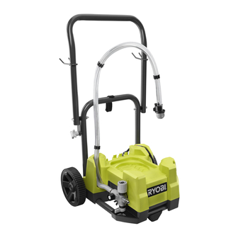
PAINT STATION TOOL
STATION DE PEINTURE
ESTACIÓN DE PINTURA
RAP200G
Your product has been engineered and manufactured to our high standard for dependability, ease of operation, and operator
safety. When properly cared for, it will give you years of rugged, trouble-free performance.
WARNING:
To reduce the risk of injury, the user must read and understand the operator's manual before using this
product. If you do not understand the warnings and instructions in the operator's manual, do not use this product.
SAVE THIS MANUAL FOR FUTURE REFERENCE
Cette produit a été conçue et fabriquée conformément aux strictes
normes de fiabilité, simplicité d'emploi et sécurité d'utilisation.
Correctement entretenu, cet outil vous donnera des années de
fonctionnement robuste et sans problème.
AVERTISSEMENT :
blessures, l'utilisateur doit lire et veiller à bien comprendre le
manuel d'utilisation avant d'employer ce produit.
Merci de votre achat.
CONSERVER CE MANUEL POUR
FUTURE RÉFÉRENCE
Pour réduire les risques de
Su producto ha sido diseñado y fabricado de conformidad con
nuestras estrictas normas para brindar fiabilidad, facilidad de
uso y seguridad para el operador. Con el debido cuidado, le
brindará muchos años de sólido funcionamiento y sin problemas.
ADVERTENCIA:
el usuario debe leer y comprender el manual del operador antes
de usar este producto.
Le agradecemos su compra.
GUARDE ESTE MANUAL PARA
FUTURAS CONSULTAS
Para reducir el riesgo de lesiones,
Advertisement
Chapters
Table of Contents

Related Manuals for Ryobi RAP200G


Summary of Contents for Ryobi RAP200G
- Page 1 PAINT STATION TOOL STATION DE PEINTURE ESTACIÓN DE PINTURA RAP200G Your product has been engineered and manufactured to our high standard for dependability, ease of operation, and operator safety. When properly cared for, it will give you years of rugged, trouble-free performance.
-
Page 2: Table Of Contents
The replacement power tool will be covered by the limited warranty for the balance of the two year period from the date of the original purchase. WHAT THIS WARRANTY COVERS: This warranty covers all defects in workmanship or materials in your RYOBI power ®... -
Page 3: Important Safety Instructions
IMPORTANT SAFETY INSTRUCTIONS WARNING: To reduce the risk of skin injection: WARNING: Do not aim the nozzle at, or spray any person or SAVE THESE INSTRUCTIONS. To reduce the risks of animal. fire or explosion, electric shock, and the injury to per- ... -
Page 4: Specific Safety Rules
SPECIFIC SAFETY RULES Keep guards in place and in working order. Never Never start the machine if ice has formed in any part operate the tool with any guard or cover removed. Make of the equipment. sure all guards are operating properly before each use. ... -
Page 5: Symbols
SYMBOLS The following signal words and meanings are intended to explain the levels of risk associated with this product. SYMBOL SIGNAL MEANING Indicates an imminently hazardous situation, which, if not avoided, will result DANGER: in death or serious injury. Indicates a potentially hazardous situation, which, if not avoided, could result WARNING: in death or serious injury. -
Page 6: Electrical
ELECTRICAL EXTENSION CORDS GROUNDING INSTRUCTIONS Use only 3-wire extension cords that have 3-prong grounding This product must be grounded. In the event of a malfunction plugs and 3-pole receptacles that accept the product’s plug. or breakdown, grounding provides a path of least resistance When using a power tool at a considerable distance from for electric current to reduce the risk of electric shock. -
Page 7: Features
FEATURES PRODUCT SPECIFICATIONS Flow Rate ................................0.24 GPM Pressure ................................800 - 2800 PSI Input ............................120 V, 60 Hz, AC only, 7.0 Amp KNOW YOUR PAINT STATION ON-BOARD ACCESSORY STORAGE See Figure 2, page 16. Paint station includes on-board accessory storage for The safe use of this product requires an understanding of convenient access to pistol-grip sprayer, spray tips, hose the information on the product and in this operator’s manual... - Page 8 ASSEMBLY CONNECTING HIGH PRESSURE HOSE/PISTOL- WARNING: GRIP SPRAYER If any parts are damaged or missing do not operate this See Figure 6, page 17. tool until the parts are replaced. Failure to heed this warn- To connect the high pressure hose to the paint station: ing could result in serious personal injury.
-
Page 9: Operation
OPERATION RELEASE PRESSURE PROCEDURE WARNING: Always follow this procedure when shutting paint station OFF for any reason. This procedure releases pressure in the Do not allow familiarity with this product to make you high pressure hose. careless. Remember that a careless fraction of a second is ... - Page 10 OPERATION Turn HIGH/LOW pressure control from LOW to HIGH until When using latex paint, spray tips need to be replaced pump starts. between 15 and 40 gallons. For oil based materials, replace spray tips after 35 to 60 gallons of use. ...
- Page 11 OPERATION • Depress the trigger to start the spray at the beginning WARNING: of the stroke and release the trigger as you end the stroke. To prevent material build-up, do not keep the To reduce the risk of fire or explosion: Do not use with trigger depressed as you proceed to the next stroke.
-
Page 12: Operation
OPERATION Soak spray tip(s) and nozzle tip guard in water (for water Turn ON/OFF switch OFF. based paints) or Klean Strip® Green Safer Paint Thinner Unplug the paint station. (for oil-based paints or varnish), rinse. Dispose of dirty water (or Klean Strip® Green Safer Paint ... -
Page 13: Maintenance
MAINTENANCE LONG-TERM STORAGE WARNING: See Figure 22, page 19. When storing the paint station for 16 hours or more, a thorough When servicing, use only identical replacement parts. cleaning is recommended. Use of any other parts may create a hazard or cause product damage. -
Page 14: Troubleshooting
TROUBLESHOOTING PROBLEM CAUSE POSSIBLE SOLUTION Motor does not run. Paint station is not plugged in Make sure unit is plugged in On/Off switch in OFF position Turn On/Off switch to ON Paint station has shut off while under Turn the high/low pressure knob to pressure maximum pressure or release pressure by turning Prime/Spray lever to Prime... - Page 15 TROUBLESHOOTING PROBLEM CAUSE POSSIBLE SOLUTION Nozzle tip guard leaks Nozzle tip guard or spray tip where Reassemble according to nozzle tip guard assembled improperly and Spray tip assembly instructions. Pistol-grip sprayer will not spray Spray tip is clogged Turn spray tip 180° and spray to clean Pistol-grip sprayer filter is clogged Clean or replace pistol-grip sprayer filter Spray tip is not fully seated into nozzle...
- Page 16 POLITIQUE D’ÉCHANGE DE 90 JOURS : En cas de défaillance due à des vices de matériaux ou de fabrication au cours des 90 jours suivant la date d’achat, l’acheteur pourra faire réparer tout outil électrique RYOBI au titre de cette garantie ®...
-
Page 17: Instructions Importantes Concernant La Sécurité
INSTRUCTIONS IMPORTANTES CONCERNANT LA SÉCURITÉ On doit retrouver un extincteur sur le lieu de travail et celui-ci AVERTISSEMENT : doit fonctionner. AVERTISSEMENT : CONSERVER CES INSTRUCTIONS. Pour réduire les Pour réduire les risques d’injection: risques d’incendie ou d’explosion, choc électrique, et la ... -
Page 18: Règles De Sécurité Particulières
RÈGLES DE SÉCURITÉ PARTICULIÈRES Maintenir tous les dispositifs de protection en place et en Ne jamais diriger un jet de peinture vers des personnes, bon état de fonctionnement. Ne jamais utiliser l’outil avec des des animaux et des appareils électriques. couvercles ou dispositifs de protection retirés. -
Page 19: Symboles
SYMBOLES Les termes de mise en garde suivants et leur signification ont pour but d’expliquer le degré de risques associé à l’utilisation de ce produit. SYMBOLE SIGNAL SIGNIFICATION Indique une situation extrêmement dangereuse qui, si elle n’est pas évitée, DANGER : aura pour conséquences des blessures graves ou mortelles. -
Page 20: Caractéristiques Électriques
CARACTÉRISTIQUES ÉLECTRIQUES CORDONS PROLONGATEURS INSTRUCTIONS DE MISE À LA TERRE Utiliser exclusivement des cordons prolongateurs à trois fils doté Ce produit doit être fondé. En cas de problème de fonctionnement d’une fiche à prise de terre brabchés sur une prise triphasée ou de panne, la mise à... -
Page 21: Caractéristiques
CARACTÉRISTIQUES FICHE TECHNIQUE Débit .....................................0,91 lpm (0.24 GPM) Pression ............................. 5 515,81 -19 305,32 kPa (800 - 2800 PSI) Alimentation ............................120 V, 60 Hz, c.a. seulement, 7,0A VEILLEZ À BIEN CONNAÎTRE STATION DE RANGEMENT POUR ACCESSOIRES PEINTURE INTÉGRÉ Voir la figure 2, page 16. La station de peinture comprend un rangement pour accessoires L’utilisation sûre de ce produit exige une compréhension des intégré... - Page 22 ASSEMBLAGE Roue ...................2 AVERTISSEMENT : Essieu..................2 Goupille de sûreté ..............2 Ne jamais utiliser la poignée pour soulever le pulvérisateur de Tuyau flexible haute pression mis peinture. Le non-respect de cette précaution peut entraîner à la terre de 7,62 m (25 pi) ............1 des blessures graves.
-
Page 23: Utilisation
UTILISATION PROCÉDURE DE LIBÉRATION DE LA AVERTISSEMENT : PRESSION Ne pas laisser la familiarité avec le produit faire oublier Toujours suivre cette procédure au moment de mettre la station de peinture à l’arrêt pour quelque raison que ce soit. Cette procédure la prudence. - Page 24 UTILISATION Tourner le levier « prime/spray » (amorçage/pulvérisation) à la REVÊTEMENTS position « SPRAY » (pulvérisation). Taille Déverrouiller la gâchette du pulvérisateur. de l’ori- Léger Moyen Lourd Tourner le régulateur de pression « HIGH/LOW » (élevée/faible) fice de la position «...
- Page 25 UTILISATION Tourner le régulateur de pression « HIGH/LOW » (élevée/faible) Appuyer sur la gâchette. Une fois que le rouleau est rempli de dans le sens horaire vers l’icône « SPRAY » (pulvérisation) (pression peinture, relâcher la gâchette; appuyer de nouveau sur celle-ci si élevée).
- Page 26 UTILISATION NETTOYAGE DE LA STATION DE PEINTURE Tourner le levier « prime/spray » (amorçage/pulvérisation) à la position « SPRAY » (pulvérisation). Voir les figures 19 à 20, page 19. Verrouiller le pistolet de pulvérisation La solution utilisée pour nettoyer le pistolet est déterminée en fonction ...
-
Page 27: Entretien
ENTRETIEN AVERTISSEMENT : AVERTISSEMENT : Utiliser exclusivement des pièces d’origine pour les Ne jamais laisser de liquides tels que le fluide de freins, réparations. L’usage de toute autre pièce pourrait créer une l’essence, les huiles pénétrantes, etc., entrer en contact avec situation dangereuse ou endommager le produit. -
Page 28: Dépannage
DÉPANNAGE PROBLÈME CAUSE SOLUTION POSSIBLE Le moteur ne tourne pas La station de peinture n’est pas branchée. S’assurer que l’unité est branchée. L’interrupteur « On/Off » (marche/arrêt) est Régler l’interrupteur « On/Off » (marche/arrêt) à réglé à la position « Off » (A<arrêt). la position «... - Page 29 DÉPANNAGE PROBLÈME CAUSE SOLUTION POSSIBLE L e m o t e u r s e m b l e f o n c t i o n n e r L’embout de pulvérisation réversible Remplacer l’embout de pulvérisation. correctement, mais la pression diminue est usé.
- Page 30 One World Technologies, Inc., garantiza sus herramientas eléctricas con las siguientes condiciones: POLÍTICA DE INTERCAMBIO A LOS 90 DÍAS: Durante los primeros 90 días a partir de la fecha de compra, usted puede solicitar servicio al amparo de esta garantía o puede intercambiar cualquier herramienta eléctrica RYOBI que no funcione correctamente ®...
-
Page 31: Reglas De Seguridad Generales
REGLAS DE SEGURIDAD GENERALES ADVERTENCIA: Para reducir el riesgo de inyección: ADVERTENCIA: No apunte la boquilla ni rocíe en dirección a personas ni animales. GUARDE ESTAS INSTRUCCIONES. Para reducir el riesgo de incendio o explosión, descanga eléctrica, y la ... -
Page 32: Reglas De Seguridad Específicas
REGLAS DE SEGURIDAD ESPECÍFICAS Mantenga las protecciones en su lugar y en buenas las exponga a la lluvia. Mantenga bien iluminada el área de condiciones de trabajo. Nunca utilice la herramienta trabajo. con ninguna de las protecciones o cubiertas quitadas. ... -
Page 33: Símbolos
SÍMBOLOS Las siguientes palabras de señalización y sus significados tienen el objeto de explicar los niveles de riesgo relacionados con este producto. SÍMBOLO SEÑAL SIGNIFICADO Indica una situación peligrosa inminente, la cual, si no se evita, causará la muerte PELIGRO: o lesiones serias. -
Page 34: Aspectos Eléctricos
ASPECTOS ELÉCTRICOS CABLES DE EXTENSIÓN VELOCIDAD Y CABLEADO La velocidad en vacío de esta herramienta es de 4800 rpm Sólo utilice cables de extensión de 3 conductores con clavijas aproximadamente. Esta velocidad no es constante y disminuye de tres puntas y contactos de tres polos que acepten la clavija durante el corte o con un voltaje bajo. -
Page 35: Características
CARACTERÍSTICAS ESPECIFICACIONES DEL PRODUCTO Caudal ................................... 0,91 lpm (0.2 4 GPM) Presión ......................... 5 515,81 -19 axle5,32 kPa (800 - 2800 PSI) Corriente de entrada ........................120 V, sólo corr. alt., 60 Hz, 7 A LUGAR PARA GUARDAR ACCESORIOS EN CONOZCA SU ESTACIÓN DE PINTURA LA UNIDAD Vea la figura 2, página 17. -
Page 36: Herramientas Necesarias
ARMADO Tapa del rodillo ................2 Rueda..................2 ADVERTENCIA: Eje....................2 Nunca use el mango para levantar el rociador de pintura. La Pasador del enganche ..............2 inobservancia de esta advertencia podría causar lesiones Manguera de alta presión con conexión personales serias. a tierra de 7,62 m (25 pies).. -
Page 37: Funcionamiento
FUNCIONAMIENTO Gire el tornillo de mariposa de seguro de apagado a la derecha ADVERTENCIA: para desasegurar el gatillo del rociador. PROCEDIMIENTO DE ALIVIO DE PRESIÓN No permita que su familarización con este producto le vuelva descuidado. Tenga presente que un descuido de un instante Siga siempre este procedimiento al apagar la estación de pintura por cualquier razón. - Page 38 FUNCIONAMIENTO Apunte el rociador con empuñadura de pistola (sin la protección CAPAS ni la punta de rociado) dentro del contenedor de desechos. Tamaño Coloque la palanca de cebado/rociado en la posición de C a r g - de la Liviana Media ROCIADO.
- Page 39 FUNCIONAMIENTO Coloque el interruptor de ENCENDIDO/APAGADO en la posición Coloque la palanca de cebado/rociado en la posición de de ENCENDIDO. ROCIADO. Prima el gatillo. Una vez que el rodillo tenga pintura, suelte el Coloque la palanca de cebado/rociado en la posición de gatillo, y oprímalo de nuevo únicamente cuando necesite más ROCIADO.
- Page 40 FUNCIONAMIENTO LIMPIEZA DE LA ESTACIÓN DE PINTURA Desasegure el gatillo del rociador con empuñadura de pistola. Apunte el rociador con empuñadura de pistola hacia el lado Vea las figuras 19 a 20 página 19. interior del contenedor de pintura original para eliminar la pintura La solución que se utiliza para limpiar el rociador se determina según del sistema y no desperdiciarla.
-
Page 41: Mantenimiento
MANTENIMIENTO GUARDADO DE LA UNIDAD A LARGO PLAZO ADVERTENCIA: Vea la figura 22, página 19. Cuando guarde la estación de pintura durante 16 horas o Al dar servicio a la unidad, sólo utilice piezas de repuesto más, se recomienda una limpieza minuciosa. idénticas. -
Page 42: Corrección De Problemas
CORRECCIÓN DE PROBLEMAS PROBLEMA CAUSA POSIBLE SOLUCIÓN El motor no funciona La estación de pintura no está A s e g ú re s e d e q u e l a u n i d a d e s t é enchufada enchufada El interruptor de encendido/apagado está... - Page 43 CORRECCIÓN DE PROBLEMAS PROBLEMA CAUSA POSIBLE SOLUCIÓN El motor parece estar funcionando bien, La punta de rociado invertible está Reemplace la punta de rociado pero la presión cae cuando se acciona desgastada la empuñadura de pistola La punta de rociado está obstruida Gire la punta de rociado 180°...
- Page 44 A - Pump (pompe, bomba ) Fig. 1 B - Prime/spray lever (Levier « prime/spray » (amorçage/pulvérisation), palanca de cebado/ rociado) C- Roller hook (crochet du rouleau, gancho del rodillo) D- Pistol-grip sprayer hook (crochet du pistolet de pulvérisation, gancho del rociador con empuñadura de pistola) E - Manual valve release button (bouton de la soupape de décharge manuelle, botón de liberación de válvula manual)
- Page 45 Fig. 4 Fig. 6 Fig. 8 A - Roller head (tête du rouleau, cabezal del rodillo) B - Roller cap (capuchon du rouleau, tapa del rodillo) C - Pin (goupille, pasador) D - Slot (fente, ranura) A - Axle (essieu, eje) E - Roller (rouleau, rodillo) B - Wheel (roue, rueda) C - Hitch pin (goupille de sûreté, pasador del...
- Page 46 Fig. 11 Fig. 13 Fig. 15 A - Orifice size increases (la taille d’orifice augmente, el tamaño del orificio aumenta) B - Fan width decreases (la largeur de ventilateur diminue, anchura del ventilador disminuye) Fig. 14 Fig. 16 A - Intake tube (tube d’admission, tubo de entrada) B - Return tube (tube de retour, tubo de retorno) C - On/Off switch (interrupteur marche/arrêt,...
- Page 47 Fig. 18 Fig. 20 Fig. 21 A - Lock-off thumbscrew (vis de blocage de la gâchette, tornillo de mariposa de seguro de apagado) B - Trigger guard (protection de gâchette, protección del gatillo) C - Filter (filtre, filtro) D - Sprayer handle (poignée de pulvérisateur, Fig.
- Page 48 • HOW TO OBTAIN CUSTOMER OR TECHNICAL SUPPORT: To obtain Customer or Technical Support please contact us at 1-800-525-2579. RYOBI is a registered trademark of Ryobi Limited and is used pursuant to a license granted by Ryobi Limited. • PIÈCES ET SERVICE Avant de faire la demande de service ou l’achat de pièces de remplacement, veuillez obtenir le numéro de série du modèle à...