Table of Contents
Advertisement
110-655B.qxd
11/27/06
I N T E G R A T E D C O M F O R T S O L U T I O N S
110-655
As an Energy Star partner, Maple Chase has
determined that this thermostat product meets
the Energy Star guide lines for energy efficiency.
Installation Guide
IMPORTANT SAFETY INFORMATION WARNING:
•
Always turn off power at the main power source by unscrewing
fuse or switching circuit breaker to the off position before installing,
removing, cleaning or servicing thermostat.
•
Read all of the information in this manual before installing or
programming this thermostat.
•
This is a 24V AC low-voltage thermostat. Do not install on voltages
higher than 30V AC.
•
All wiring must conform to local and national building and electrical
codes and ordinances.
•
Do not short (jumper) across terminals on the gas valve or at the
system control to test installation. This will damage the thermostat
and void the warranty.
4:38 PM
Page 1
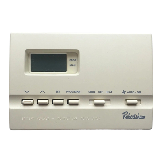
9610
®
G
E
™
ELECTRIC
GAS
7 Day Programmable
1 Heat / 1 Cool
User's Manual
Quick Start
Installation and
Programming
1
DIGITAL
PROGRAMMABLE
THERMOSTAT
Advertisement
Table of Contents

Related Manuals for Robertshaw 9610


Summary of Contents for Robertshaw 9610
-
Page 1: Quick Start
110-655B.qxd 11/27/06 4:38 PM Page 1 9610 DIGITAL PROGRAMMABLE THERMOSTAT ® ™ I N T E G R A T E D C O M F O R T S O L U T I O N S ELECTRIC 7 Day Programmable 1 Heat / 1 Cool User’s Manual... -
Page 2: Replacing Existing Thermostat
110-655B.qxd 11/27/06 4:38 PM Page 2 Features • Four pre-programmed Energy Star setpoints for each day of the week. • Two “AA” ENERGIZER brand batteries retain program memory, even during power outages. • Low battery indicator. • Fahrenheit/Celsius display option. •... -
Page 3: Installation
110-655B.qxd 11/27/06 4:38 PM Page 3 Figure 1 Installing Item 9610 Thermostat NOTE: F , 4-5 OR NEW INSTALLATIONS MOUNT THERMOSTAT ON INSIDE WALL FEET ABOVE THE FLOOR O NOT INSTALL BEHIND A DOOR IN A CORNER NEAR AIR VENTS... - Page 4 110-655B.qxd 11/27/06 4:38 PM Page 4 Figure 3 MOUNTING HOLES 7. Drill the marked holes using a 3/16” drill bit. 8. Tap plastic anchors into the holes. 9. Align base with plastic anchors and feed wires through opening. See Fig 4. Figure 4 10.
-
Page 5: Set Time Of Day/Day Of Week
110-655B.qxd 11/27/06 4:38 PM Page 5 14. Install two “AA” ENERGIZER brand batteries or equivalent into bat- tery compartment. Be sure to place positive (+) ends of batteries toward (+) battery terminals in the battery compartment. The display will show as follows: 15. -
Page 6: Quickset Programming Mode
110-655B.qxd 11/27/06 4:38 PM Page 6 3. Press Press SET P To change Temperature Differential* 1°. T EMPERATURE IFFERENTIAL IS ACTORY PRESET AT HIS MEANS THAT WHENEVER THE ROOM TEMPERATURE CHANGES BY ONE FULL DEGREE FROM THE TEMPERATURE SETTING THE SYSTEM WILL TURN ON F THE SYSTEM TURNS ON TOO OFTEN INCREASE THE TEMPERATURE DIFFERENTIAL... -
Page 7: Begin Programmed Operation
110-655B.qxd 11/27/06 4:38 PM Page 7 Setting Daily Programming Summer (Cool) Settings: 1. Place COOL-OFF-HEAT COOL-OFF-HEAT in COOL position. PROG SET PROG/MAN COOL-OFF-HEAT AUTO - ON SET PR 2. Press SET button. The display will show a number from 1 to 7. This number represents the day of the week to be programmed If pro- gramming individual days, press... -
Page 8: Reset
110-655B.qxd 11/27/06 4:38 PM Page 8 3. Press PROG/MAN button ET PROG/MAN until indicator is in PROG position. PROG SET PROG/MAN COOL-OFF-HEAT AUTO - ON PROG NOTE: W HILE IN THE OOL MODE OR HEAT AND COOL FOR SINGLE STAGE HEAT PUMP SYSTEM ONCE THE THERMOSTAT TURNS THE SYSTEM OFF A BUILT... -
Page 9: To Test Thermostat
110-655B.qxd 11/27/06 4:38 PM Page 9 To Test Thermostat WARNING: DO NOT SHORT (JUMPER) ACROSS TERMINALS OF GAS VALVE OR SYS- TEM CONTROL TO TEST OPERATION. THIS WILL DAMAGE THE THERMOSTAT AND VOID YOUR WARRANTY. CAUTION: D 50°F (10°C). T O NOT SWITCH SYSTEM TO COOL IF THE TEMPERATURE IS BELOW CAN DAMAGE THE AIR CONDITIONING SYSTEM AND CAUSE PERSONAL INJURY COOL-OFF-HEAT... -
Page 10: Troubleshooting
110-655B.qxd 11/27/06 4:38 PM Page 10 Troubleshooting SYMPTOM REMEDY Thermostat does not Check Wiring turn on system (See INSTALLATION) Check fuse. Replace with 3 amp fuse if fuse has opened. Thermostat turns on and off Increase Temperature Differential too frequently. (See PROGRAMMING). -
Page 11: Wiring Diagrams
110-655B.qxd 11/27/06 4:38 PM Page 11 Wiring Diagrams The following is just a sample of the most common types of HVAC sys- tems. Refer to your systems installation manual for wiring information. HEAT ONLY HEAT/COOL 3-WIRE 4-WIRE SINGLE TRANSFORMER SINGLE TRANSFORMER Factory-Installed Factory-Installed Jumper... -
Page 12: Five Year Limited Warranty
110-655B.qxd 11/27/06 4:38 PM Page 12 Wiring Diagrams (cont’d) HEAT PUMP WITH HEAT PUMP WITH COOL ACTIVE HEAT ACTIVE REVERSING VALVE REVERSING VALVE NOTE: Factory NOTE: Factory Installed Jumper Installed Jumper Transformer Transformer 120 VAC 24 VAC 120 VAC 24 VAC Compressor Compressor Contactor...