Empire Comfort Systems VFP32BP20LN-1 Installation Instructions And Owner's Manual
Vent-free gas fireplaces
Hide thumbs
Also See for VFP32BP20LN-1:
- Owner's manual (28 pages) ,
- Installation instructions and owner's manual (40 pages)
Table of Contents
Advertisement
Vent-Free Gas Fireplaces
Installer:
Leave this manual with the appliance.
Consumer: Retain this manual for future reference.
WARNING: If the information in these instruc-
tions are not followed exactly, a fire or explo-
sion may result causing property damage,
personal injury or loss of life.
— Do not store or use gasoline or other flam-
mable vapors and liquids in the vicinity of
this or any other appliance.
— WHAT TO DO IF YOU SMELL GAS
• Do not try to light any appliance.
• Do not touch any electrical switch; do not
use any phone in your building.
• Immediately call your gas supplier from
a neighbor's phone. Follow the gas sup-
plier's instructions.
• If you cannot reach your gas supplier,
call the fire department.
— Installation and service must be performed
by a qualified installer, service agency or the
gas supplier.
INSTALLATION INSTRUCTIONS
AND OWNER'S MANUAL
UNVENTED
GAS FIREPLACE
MODELS
HYDRAULIC MODELS
VFP(32,36)BP2(0,1)L(N,P)-1
MILLIVOLT MODELS
VFP(32,36)BP3(0,1)L(N,P)-1
INTERMITTENT PILOT MODELS
VFP(32,36)BP7(0,1)L(N,P)-1
This appliance may be installed in an aftermar-
ket, permanently located, manufactured (mobile)
home, where not prohibited by local codes.
This appliance is only for use with the type of gas
indicated on the rating plate. This appliance is not
convertible for use with other gases.
This is an unvented gas-fired heater. It uses air
(oxygen) from the room in which it is installed.
Provisions for adequate combustion and ventila-
tion air must be provided. Refer to page 8.
WARNING: If not installed, operated and main-
tained in accordance with the manufacturer's
instructions, this product could expose you to
substances in fuel or from fuel combustion which
can cause death or serious illness.
WATER VAPOR: A BY-PRODUCT OF UNVENTED
ROOM HEATERS
Water vapor is a by-product of gas combustion.
An unvented room heater produces approximately
one (1) ounce (30ml) of water for every 1,000 BTU's
(.3KW's) of gas input per hour. Refer to page 8.
Page 1
Advertisement
Table of Contents
Troubleshooting

Related Manuals for Empire Comfort Systems VFP32BP20LN-1


Summary of Contents for Empire Comfort Systems VFP32BP20LN-1
- Page 1 INSTALLATION INSTRUCTIONS AND OWNER'S MANUAL Vent-Free Gas Fireplaces UNVENTED GAS FIREPLACE MODELS HYDRAULIC MODELS VFP(32,36)BP2(0,1)L(N,P)-1 MILLIVOLT MODELS VFP(32,36)BP3(0,1)L(N,P)-1 INTERMITTENT PILOT MODELS VFP(32,36)BP7(0,1)L(N,P)-1 Installer: Leave this manual with the appliance. This appliance may be installed in an aftermar- Consumer: Retain this manual for future reference. ket, permanently located, manufactured (mobile) home, where not prohibited by local codes. WARNING: If the information in these instruc- This appliance is only for use with the type of gas tions are not followed exactly, a fire or explo- indicated on the rating plate. This appliance is not sion may result causing property damage, convertible for use with other gases. personal injury or loss of life.
-
Page 2: Table Of Contents
TABLE OF CONTENTS SECTION PAGE WARRANTY ........................3 IMPORTANT SAFETY INFORMATION ................4 SAFETY INFORMATION FOR USERS OF LP-GAS ............5 INTRODUCTION ....................... 6 SPECIFICATIONS ......................7 WATER VAPOR: A BY-PRODUCT OF UNVENTED ROOM HEATERS ......8 PROVISIONS FOR ADEQUATE COMBUSTION & VENTILATION AIR ......8-9 GAS SUPPLY ........................9-10 CLEARANCES ......................... -
Page 3: Warranty
WARRANTY Empire Comfort Systems Inc. warranties this hearth product to be free from defects at the time of purchase and for the periods speci- fied below. Hearth products must be installed by a qualified technician and must be maintained and operated safely, in accordance with the instructions in the owner’s manual. -
Page 4: Important Safety Information
IMPORTANT SAFETY INFORMATION DANGER: Indicates a hazardous situation which, if not avoided, will • WARNING: DO NOT operate this appliance unless all result in death or serious injury. components including logs, burners, and controls are in good working condition. Never operate this appliance if any log or WARNING: Indicates a hazardous situation which, if not avoided, twig is broken, or out of their intended position. Refer to the could result in death or serious injury. -
Page 5: Safety Information For Users Of Lp-Gas
SAFETY INFORMATION FOR USERS OF LP-GAS Propane (LP-Gas) is a flammable gas which can cause fires point with the members of your household. Someday when and explosions. In its natural state, propane is odorless and there may not be a minute to lose, everyone's safety will depend colorless. You may not know all the following safety precau- on knowing exactly what to do. If, after reading the following tions which can protect both you and your family from an information, you feel you still need more information, please accident. Read them carefully now, then review them point by contact your gas supplier. LP-GAS WARNING ODOR If a gas leak happens, you should be able to smell the gas because of the odorant put in the LP-Gas. That's your signal to go into immediate action! • Do not operate electric switches, light matches, use your •... -
Page 6: Introduction
INTRODUCTION Instructions to Installer 1. Installer must leave instruction manual with owner after Installation on Rugs and Tile installation. If this appliance is installed directly on carpeting, tile or other 2. Installer must have owner fill out and mail warranty card combustible material other than wood flooring the appliance supplied with unvented room heater. -
Page 7: Specifications
SPECIFICATIONS Model VFP32BP VFP36BP Input Maximum 32,000 36,000 Minimum 22,000 25,000 Minimum Firebox Opening Height without standoff 32 3/4" 34 3/4" Width 34” 39” Depth 17 3/8" 17 3/8” Gas Inlet 3/8” 3/8” Accessories EK-1 Embers Kit PE-20 Platinum Embers FBB4* Variable Speed Automatic Blower VPP32A VFP32BP —... -
Page 8: Water Vapor: A By-Product Of Unvented Room Heaters
WATER VAPOR: A BY-PRODUCT OF UNVENTED ROOM HEATERS become a problem. Water vapor is a by-product of gas combustion. An unvented room 1. Be sure the heater is sized properly for the application, including heater produces approximately one (1) ounce (30ml) of water for every 1,000 BTU's (.3KW's) of gas input per hour. - Page 9 PROVISIONS FOR ADEQUATE COMBUSTION & VENTILATION AIR (continued) Ventilation Air From Outdoors (Figure 2) The space in the above example is a confined space because the Provide extra fresh air by using ventilation grills or ducts. You must actual BTU/Hr used is more than the maximum BTU/HR the space provide two permanent openings: one within 12"...
-
Page 10: Gas Supply
GAS SUPPLY Check all local codes for requirements, especially for the size and The use of the following gas connectors is recommended: type of gas supply line required. — ANS Z21.24 Appliance Connectors of Corrugated Metal Tubing and Fittings Recommended Gas Pipe Diameter —... -
Page 11: Clearances
GAS SUPPLY (continued) Checking Manifold Pressure VFP(32,36)BP(30,31)LP (Propane gas) will have a manifold pressure approximately 10.0"w.c. (2.49kPa) for maximum input or 4.9"w.c. VFP(32,36)BP(20,21)LN (Natural gas) will have a manifold pressure (1.220kPa) for minimum input at the pressure regulator outlet with the of approximately 6.0" w.c. (1.49kPa) at the pressure regulator outlet inlet pressure to the pressure regulator from a minimum of 11.0"w.c. -
Page 12: Combustible Materials
COMBUSTIBLE MATERIALS Do not attach combustible material to the mantel of your fireplace. No greeting cards, stockings or ornamentation of any type should be This is a fire hazard. placed on or attached to the fireplace. This is a heating appliance. The flow of heat can ignite combustibles. -
Page 13: Fireplace Dimensions
FIREPLACE DIMENSIONS STANDOFF GAS LINE OPENING GAS LINE OPENING JUNCTION BOX ASSEMBLY VFP32BP VFP36BP 34" 39" 29" 34" 17 3/8" 17 3/8" 31" 36" 22 7/8" 24 7/8" 32 3/4" 34 3/4" 31 7/8" 34 3/8" 45 1/8" 48 5/8" 63 3/4"... -
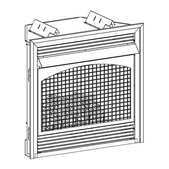
Page 14: Installing Hood And Trim Kit
INSTALLING HOOD AND TRIM KIT A black hood and trim kit is furnished with each model Finishing VFP(32,36)BP fireplace. The hood MUST be installed before the All joints (top, bottom and sides), where the wall or decorative facing fireplace is used. Failure to do so may create a possible fire hazard. material meets the fireplace surround must be completely sealed Attention: The hood is located behind top louver during shipment with a non-combustible material. -
Page 15: Fireplace Framing And Installation
FIREPLACE FRAMING AND INSTALLATION Fireplace framing can be built before or after the fireplace is set in 1. Place fireplace in framing opening. place. Framing should be positioned to accommodate wall covering 2. Using the four (4) nailing flanges provided with the fireplace, and fireplace facing material. -
Page 16: Placement Of Glowing Embers And Lava Rock
Rock wool should not be placed in the area of the pilot assembly. Replacement of loose material (glowing embers) must be purchased from Empire Comfort Systems, Inc. Application of excess loose material (glowing embers) may adversely affect performance of the heater. WARNING: All previously applied loose material must be removed prior to reapplication. -
Page 17: Vfp(32,36)Bp(30,31) Lighting Instructions
VFP(32,36)BP(30,31) LIGHTING INSTRUCTIONS FOR YOUR SAFETY READ BEFORE LIGHTING WARNING: If you do not follow these instructions exactly, a fire or explosion may result causing property damage, personal injury or loss of life. A. This appliance has a pilot which must be lighted by • If you cannot reach your gas supplier, call the fire hand. When lighting the pilot, follow these instructions department. exactly. C. Use only your hand to push in or turn the gas control B. BEFORE LIGHTING smell all around the appliance area knob. Never use tools. If the knob will not push in or for gas. Be sure to smell next to the floor because some... -
Page 18: Vfp(32,36)Bp(20,21) Lighting Instructions
VFP(32,36)BP(20,21) LIGHTING INSTRUCTIONS FOR YOUR SAFETY READ BEFORE LIGHTING WARNING: If you do not follow these instructions exactly, a fire or explosion may result causing property damage, personal injury or loss of life. A. This appliance has a pilot which must be lighted by • If you cannot reach your gas supplier, call the fire hand. When lighting the pilot, follow these instructions department. exactly. C. Use only your hand to push in or turn the gas control B. BEFORE LIGHTING smell all around the appliance area knob. Never use tools. If the knob will not push in or for gas. Be sure to smell next to the floor because some... -
Page 19: Vfp(32,36)Bp(70,71) Lighting Instructions
VFP(32,36)BP(70,71) LIGHTING INSTRUCTIONS FOR YOUR SAFETY READ BEFORE LIGHTING WARNING: If you do not follow these instructions exactly, a fire or explosion may result causing property damage, personal injury or loss of life. A. This appliance has a pilot which can be lighted with the manual • If you cannot reach your gas supplier, call the fire depart- on/off switch, a remote control, or by switching the remote ment. -
Page 20: Operation Instructions/Flame Appearance
OPERATION INSTRUCTIONS/FLAME APPEARANCE Flames from the pilot (rear right back side of the pan burner) as PERIODIC CLEANING – Refer to parts diagram for location of well as the main flame should be visually checked as the log set items discussed below. is installed. • Do not use cleaning fluid to clean logs or any part of heater. •... -
Page 21: Pilot Flame Characteristics
PILOT FLAME CHARACTERISTICS Figures 13, 15 and 17 show a correct pilot flame pattern. The correct HYDRAULIC THERMOSTAT PILOT Correct Pilot Flame Pattern flame will be blue and will extend beyond the thermocouple. The PILOT flame will surround the thermocouple just below the tip. A slight yellow flame may occur where the pilot flame and main burner flame meet. - Page 22 PILOT FLAME CHARACTERISTICS INTERMITTENT PILOT Cleaning and Pilot Maintenance Oxygen Depletion Sensor Pilot Correct Pilot Flame Pattern When the pilot has a large yellow tip flame, clean the Oxygen IGNITOR Depletion Sensor as follows: Clean the ODS pilot by loosening nut B from the pilot tubing. SENSOR When this procedure is required, grasp nut A with an open end wrench.
-
Page 23: Millivolt Wiring
MILLIVOLT WIRING Label all wires prior to disconnection when servicing REMOTE CONTROL RECEIVER/ THERMOSTAT/CONTROLE E controls. Wiring errors can cause improper and DISTANCE DU RECEPTEUR WIRING DIAGRAM dangerous operation. Verify proper operation after servicing. (OPTIONAL) THERMOSTAT Millivolt thermopile is self powered, gas valve does (FACULATIVE) THERMOSTAT not require 110 volts. -
Page 24: Millivolt And Hydraulic Troubleshooting
MILLIVOLT AND HYDRAULIC TROUBLESHOOTING SYMPTOMS - POSSIBLE CAUSES AND CORRECTIONS Turn appliance OFF and allow to cool before servicing. Only a qualified service person should service and repair the heater. a. Control knob not fully pressed in - Press in control 1. When ignitor button is pressed, there is no spark at ODS/pilot. -
Page 25: Intermittent Control System Operating Instructions
INTERMITTENT CONTROL SYSTEM OPERATING INSTRUCTIONS 5.25 VDC ELECTRONIC CONTROL VALVE Follow the SAFETY and LIGHTING INSTRUCTIONS for In- termittent Pilot controls found in this manual, and on labels The electronic control valve system includes the ability to switch found in the control compartment located in the lower cavity the pilot from a standing pilot mode to an intermittent pilot mode. -
Page 26: Intermittent Control System Wiring Diagram
INTERMITTENT CONTROL SYSTEM WIRING DIAGRAM BLUE BLUE GREEN WHITE WHITE CPI/IPI ORANGE SWITCH ON/OFF REMOTE RECEIVER PILOT SWITCH (OPTIONAL) YELLOW + ON REMOTE - OFF BLACK BLACK GAS CONTROL VALVE (GND) WHITE GREEN BLACK AC/DC POWER ADAPTOR BLACK ELECTRONIC CONTROL MODULE BATTERY HOLDER Figure 24 If any of the original wire as supplied with this unit must be replaced, it must be replaced with equivalent gauge and temperature... -
Page 27: Intermittent Control System Troubleshooting
INTERMITTENT CONTROL SYSTEM TROUBLESHOOTING Brief Description of the Components The gas valve is equipped with a manual HI/LO knob to allow for manual modulation of the gas outlet pressure. The manual HI/LO knob can be replaced by an Empire Comfort Systems Variable Remote Kit. WARNING This appliance is equipped for Natural or Propane gas. - Page 28 INTERMITTENT CONTROL SYSTEM TROUBLESHOOTING If the DFC giving signal lock out: Verify the electrical connections’ integrity and The board should be unlocked to make sure they are in accordance with the relevant reinitiate a pilot flame ignition (for Is the DFC board in system wiring diagram.
- Page 29 INTERMITTENT CONTROL SYSTEM TROUBLESHOOTING Replace DFC board. Main burner lights when the pilot only Replace the gas valve. should light. Verify the pilot flame fully engulfs the tip of the sense electrode. If not replace the pilot assembly. Replace the pilot assembly. Carefully clean the electrical connections of the sense cable, and the DFC board sense cable connection.
-
Page 30: Optional Variable Speed Blower Installation Instructions
OPTIONAL VARIABLE SPEED BLOWER INSTALLATION INSTRUCTIONS FBB4 Blower Installation Attention: Install blower assembly before connecting gas inlet supply line. Note: Junction box on right side of fireplace must be pre- wired at time of fireplace installation for use with blower assembly. It is recommended that an ON/OFF wall switch be installed that will activate the power supply to the furnace by a qualified electrician. - Page 31 OPTIONAL VARIABLE SPEED BLOWER INSTALLATION INSTRUCTIONS (continued) Wiring Blower Motor The appliance, when installed, must be electrically grounded in The blower motor does not have oiling holes. Do not attempt to oil the blower motor. accordance with local codes or, in the absence of local codes, with the National Electrical Code, ANSI/NFPA 70, if an external Blower Wheels electrical source is utilized.
-
Page 32: Junction Box Wiring Installation Instructions
JUNCTION BOX WIRING INSTALLATION INSTRUCTIONS CAUTION: ALL WIRING SHOULD BE DONE BY A QUALIFIED ELECTRICIAN AND SHALL BE IN COMPLIANCE WITH ALL LOCAL, CITY AND STATE BUILDING CODES. BEFORE MAKING THE ELECTRICAL CONNECTION, MAKE SURE THAT MAIN POWER SUPPLY IS DISCONNECTED. THE APPLIANCE, WHEN INSTALLED, MUST BE ELECTRICALLY GROUNDED IN ACCORDANCE WITH LOCAL CODES OR, IN THE ABSENCE OF LOCAL CODES, WITH THE NATIONAL ELECTRICAL CODE ANSI/NFPA 70 (LATEST EDITION). A factory installed junction box is located on the lower right hand side of the fireplace. Wiring must be fed to the junction box and attached to the receptacle that is provided. -
Page 33: Master Parts Distributor List
This list changes from time to time. For the current list, please click on the Master Parts button at www.empirecomfort.com. Please note: Master Parts Distributors are independent businesses that stock the most commonly ordered Original Equipment repair parts for Heaters, Grills, and Fireplaces manufactured by Empire Comfort Systems Inc. Dey Distributing Victor Division of F. W. Webb Company... -
Page 34: Vfp32Bp(2,3,7) Parts List
VFP32BP(2,3,7) PARTS LIST ATTENTION: When ordering parts, it is very important that part number and description of part coincide. Part Number Index Description VFP32BP2 VFP32BP3 VFP32BP7 17149 17149 17149 TOP STANDOFF 20098 20098 30609 FIREBOX ASSEMBLY 10554 10554 10554 NAILING FLANGE 20170 20170 20170... - Page 35 VFP32BP(2,3,7) PARTS LIST ATTENTION: When ordering parts, it is very important that part number and description of part coincide. Part Number Index Description VFP32BP2 VFP32BP3 VFP32BP7 P239 NIPPLE, 3/8 NPT X 1 1/2 R6427 REGULATOR, NAT 6.0” W.C. (NAT ONLY) R6428 REGULATOR, LP 10.0”...
-
Page 36: Vfp36Bp(2,3,7) Parts List
VFP36BP(2,3,7) PARTS LIST ATTENTION: When ordering parts, it is very important that part number and description of part coincide. Part Number Index No. Description VFP36BP2 VFP36BP3 VFP36BP7 17149 17149 17149 TOP STANDOFF 20126 20126 30616 FIREBOX ASSEMBLY 10554 10554 10554 NAILING FLANGE 20134 20134 20134... - Page 37 VFP36BP(2,3,7) PARTS LIST ATTENTION: When ordering parts, it is very important that part number and description of part coincide. Part Number Index No. Description VFP36BP2 VFP36BP3 VFP36BP7 R7063 R7063 REGULATOR, PILOT (NAT ONLY) 20116 29816 TUBING ASSEMBLY (NAT ONLY) P239 NIPPLE, 3/8 NPT X 1 1/2 R6427 REGULATOR, NAT 6.0”...
-
Page 38: Parts View
PARTS VIEW HYDRAULIC MILLIVOLT VALVE ASSEMBLY VALVE ASSEMBLY INTERMITTENT PILOT (IP) VALVE ASSEMBLY Page 38 29898-8-1114... -
Page 39: Warranty
WARRANTY Empire Comfort Systems Inc. warranties this hearth product to be free from defects at the time of purchase and for the periods speci- fied below. Hearth products must be installed by a qualified technician and must be maintained and operated safely, in accordance with the instructions in the owner’s manual. - Page 40 Empire Comfort Systems Inc. 918 Freeburg Ave. Belleville, IL 62220 If you have a general question about our products, please e-mail us at info@empirecomfort.com. If you have a service or repair question, please contact your dealer. www.empirecomfort.com Page 40 29898-8-1114...