
Related Manuals for LevelOne FCS-3091


Summary of Contents for LevelOne FCS-3091
- Page 1 FCS-3091 User’s Manual FCS-3091 2-Megapixel Fish-Eye PoE Dome Network Camera User’s Manual Version: 1.3 Date: 03/07/2012...
-
Page 2: Table Of Contents
FCS-3091 User’s Manual Contents General Public License ........................... 2 Notices ................................3 Introduction ..............................4 Installation ..............................5 Terminal block for I/O connectors ....................7 Using the Web UI ............................16 1. Live View ............................17 2. Video ..............................20 General ............................ -
Page 3: General Public License
If you would like a copy of the GPL or other open source code in this software on a physical CD medium, LevelOne (Digital Data Communications) offers to mail this CD to you upon request, for a price of US$9.99 plus the cost of shipping. -
Page 4: Notices
FCS-3091 User’s Manual Notices This user manual is intended for administrators and users of the FCS-3091 Network Camera, including instructions for using and managing the camera on your network. The use of surveillance devices may be prohibited by law in your country. It is the user’s responsibility to ensure that the operation of such devices is legal before installing this unit for its intended use. -
Page 5: Introduction
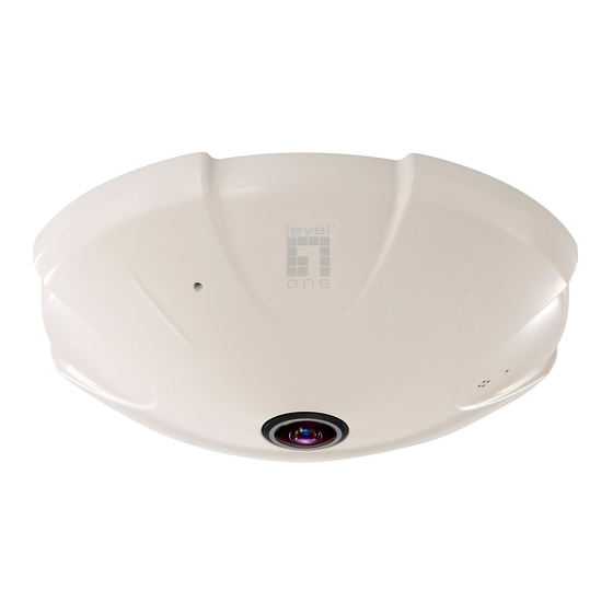
FCS-3091 User’s Manual Introduction FCS-3091 is a Fish-Eye Panorama Network Dome Camera featured with 2Mega Pixel resolution and superior H.264-AVC performance and rich functions. FCS-3091 includes a fish-eye lens for 360° panoramic wide angle view without blind spot. It is very suitable to view a wide area with single camera such as hallway, store, and office without the need to install multiple cameras. -
Page 6: Installation
FCS-3091 User’s Manual Installation FCS-3091 – Physical Overview Interface Description Light Sensor The Light sensor is for detecting IP Camera environmental illumination, and if IP Camera was in the dark/night environment, IR Cut Filter is switched off to let infrared light pass through for clear night view. - Page 7 FCS-3091 User’s Manual Interface Contents Power Jack The input power is DC 12V, 2A. Note: ONLY use package power adapter supplied with the internet. Otherwise, the product may be damaged. RJ-45 LAN Socket Connect to PC or Hub / Switch.
-
Page 8: Terminal Block For I/O Connectors
FCS-3091 User’s Manual Terminal block for I/O connectors Function Description Four sets of Digital Input, DI1 until DI4; the internal device is also Digital input 4 photo-coupled electrical relay. In practice, the external device can be Digital input 3 simply an On/Off switch. Four sets of On/Off switch can be connected as Digital input 2 different trigger source. - Page 9 FCS-3091 User’s Manual 2. Mounting Bracket Installation Carefully follow the steps to ensure correct installation.
-
Page 10: Software Installation
FCS-3091 User’s Manual 3. Software Installation The following software is necessary for the proper display and use of the FCS-3091 from the Web site. The software will be taken from the Software Package CD. IP Installer The IP Installer is used to locate and configure network cameras and video servers on the LAN. This utility is useful for conveniently configuring the network settings of the device, or for finding a device once the network settings have been modified. -
Page 11: Network Configuration
(S/N) with 12 digits (e.g. 00116B-XXXXXX). Although the IP Installer is able to find and configure any FCS-3091 on the LAN except those that are behind a router, it is a good idea to set the host PC to the same subnet. In order to connect to the Web-based user interface of the camera, the host PC must be in the same subnet. - Page 12 FCS-3091 User’s Manual 3. From the list, select the device with the MAC Address that corresponds to the camera that is to be configured. The MAC Address is identical to the unit’s S/N (Serial Number). 4. Double click the select item to open the Property Page or right click the item to select the [Single Device Setting].
- Page 13 FCS-3091 User’s Manual After filling in the properties, click [Set] button to complete the configuration settings. Click the [Batch Device Setting] to set several devices.
- Page 14 FCS-3091 User’s Manual Language support for Chinese, English and Spanish.
- Page 15 FCS-3091 User’s Manual Open the Web-based UI of the selected camera To access the Web-based UI of the selected unit, run the Open Web on the select item For first time user, there will be a prompt to install the ActiveX control. Confirm the installation as it is required to view the video stream and some operations.
- Page 16 FCS-3091 User’s Manual Verify and Complete the Installation from Your Browser When browsing the Home Page at the first time with the Microsoft Internet Explorer , you must temporarily lower your security settings to perform a one-time-only installation of the ActiveX...
-
Page 17: Using The Web Ui
FCS-3091 User’s Manual Using the Web UI Start your Web browser and enter the URL or IP address in the Address field. The Home page of the camera is now displayed. -
Page 18: Live View
FCS-3091 User’s Manual 1. Live View Video format Bit rate IP address of the camera Resolution Frame Rate Button Description Click for more general/advance camera settings Select languages among English, traditional Chinese and simplify Chinese Select display mode to view the different type of the video layout. - Page 19 FCS-3091 User’s Manual Button Description Full screen Listen the audio input from local end Talk function Record instant live video Snapshot the image...
- Page 20 FCS-3091 User’s Manual Configuration Pages List Video General Advance External Video Source Camera General Advance Event Event Server Motion Detection I/O ports Event Configuration Schedule General Storage Network ...
-
Page 21: Video
The PTZ function will display in Broad view, Quad view, Quad with source view, Double view and Triple view of Ceiling Mount. Click on the PTZ icon, the web will popup the control panel to control e-PTZ function of FCS-3091. - Page 22 FCS-3091 User’s Manual Broad view PTZ control panel: 1. Step: Setting the speed of Pan function. (1~10) 2. Pan Arrow: Click to control Pan function. 3. Move the control panel. 4. Close the control panel.
- Page 23 FCS-3091 User’s Manual Quad view & Quad with source view PTZ control panel: 1. Ch:Select the channel. (1~4) & (2~4) 2. Step:Setting the speed of Pan/Tilt function. (1~10) 3. Pan Tilt Arrow:Click to control Pan/Tilt function. 4. Zoom:Digital zoom in/out. (1~10) 5.
- Page 24 FCS-3091 User’s Manual Advanced Stream 1 Setting: RTSP Path: It is the stream ID used for RTSP client streaming connection, such as VLC player. (default v00) Resolution: 1600x1200, 800x600, 640x480. Video Mode: Choose between variable bit rate (VBR) and constant bit rate (CBR) VBR->...
-
Page 25: Camera
FCS-3091 User’s Manual 3. Camera General... - Page 26 FCS-3091 User’s Manual Camera General Setting: Brightness: the luminance of image view. Hue: refer to pure color, it can modify the different display of specific color such as red, green or blue. Saturation: intensity of a specific color.
-
Page 27: Advance
White balance: Adjustment to compensate for different environments in terms of light source, user can choose auto/hold/sunny/coludy/indoor so that FCS-3091 can determine the correct color compensation due to different light environment. Be noted that hold indicate that the parameter will apply default setting. - Page 28 FCS-3091 User’s Manual Infrared (IR) Cut Filter: The default is automatically switched according to light intensity. Enable indicate the filter is enable to cut IR light to make sure the color is correct, Disable indicate the filter is disable and allow the infrared (such as IR LED illuminator) to enter the camera to execute low lux surveillance...
- Page 29 FCS-3091 User’s Manual 3. Quad with source view: 4. Triple view: Ceiling Mount: Choose Ceiling mount, Go back to live view, there are 6 kinds of video layout to choose from; Original view, Broad view, Quad view, Quad with source view, Double view and Triple view.
- Page 30 FCS-3091 User’s Manual 3. Quad view: 4. Quad with source view: 5. Double view: 6. Triple view:...
- Page 31 FCS-3091 User’s Manual Table Mount: Choose Table mount, Go back to live view, there are 2 kinds of video layout to choose from; Original view and Double view 1. Original view: 2. Double view:...
-
Page 32: Event
FCS-3091 User’s Manual 4. Event Event Server Click on the [Add FTP] to expand FTP server setting. FTP Server: Name: Give a name for the FTP server Network Address: Input the network address of the FTP server ... -
Page 33: Motion Detection
FCS-3091 User’s Manual Motion Detection To add a motion detection area: 1. Click on [Add] to set up a detection area. (Set up panel will be expanded) - Page 34 FCS-3091 User’s Manual 2. Give a name to this window area. 3. Select the trigger level and sensitivity for this detection window. (0~100, low~high) 4. Select color for detection window. 5. Draw detection window on the image.
- Page 35 FCS-3091 User’s Manual 6. Once everything is done, click on [Save] to save the configuration made. Configured detection window will be displayed in motion detection list. (Circled in blue) Note: 1. Maximum number of detection window is 10. 2. Motion Detection windows need to be modified if users changed video layout.
-
Page 36: I/O Ports
FCS-3091 User’s Manual I/O Ports This model supports 4 photo-coupled relay inputs and 1 relay outputs, see “I/O Terminal Connectors” for detail pin description and application. The tab shows the status of them; with external trigger/alarm devices. -
Page 37: Event Configuration
FCS-3091 User’s Manual Event Configuration 1. To add an event trigger, click on [Add] and setup panel will be expanded. 2. Give a name to this event. 3. Set the time interval between each trigger. 4. Set the time period for the trigger. Choose “Always” or “During time between” or “Never”. -
Page 38: Schedule
FCS-3091 User’s Manual 5. Schedule General Define the day (specified by days of a week) and time (specified by each single hour) for that will be recording during the scheduled period. Note that only video data will be recorded. User can select which video stream should be recorded, and the size of each sliced file. -
Page 39: Storage
FCS-3091 User’s Manual Storage Display the storage information, includes disk size info, type and status. The warning message shows when recording is on process; Micro SD card should not be removed during the recording process. -
Page 40: Network
FCS-3091 User’s Manual 6. Network General Device IP configuration, includes DHCP and Static IP setting. “Enable ARP/Ping” enable device to accept ARP or ping packets from the network. Disable this option may provide extra security from intentional ping. -
Page 41: Advanced
FCS-3091 User’s Manual Advanced Enable or configure other network functions. NTP: Configure a NTP (Network Time Protocol) server, so that the device system date and time can be synchronized with a specified Time Server or DHCP server. HTTP: set the HTTP port that will be applied for Web UI access. -
Page 42: Smtp (E-Mail)
FCS-3091 User’s Manual SMTP (E-Mail) Configure an email host in the device that will send email on behalf of the configured email account in a circumstance like sending an email notice to a specified mail address (Event Configuration). Complete the Mail Server, Server Port, Authentication information (if required) and the sender email address. -
Page 43: Ddns
FCS-3091 User’s Manual DDNS Dynamic DNS configuration; the network device can be assigned with a host name by registering this service (Internet access required). Host Name: Assigned name that will be used for access to the device User Name/Password: Account authentication for logging to this service Update Time: Periodically, the device updates its access info to sever in the configured time. -
Page 44: System
FCS-3091 User’s Manual 7. System Information Lists of System and Network configurations... -
Page 45: User
FCS-3091 User’s Manual User Login users for Web access and operations; authentication required. The Check box is for anonymous logging on to the live view page. Logging for further configurations will still require user name and password. -
Page 46: Date & Time
FCS-3091 User’s Manual Date & Time System date/time configuration. Options of synchronizing with PC and NTP server are provided for automatic adjustment. -
Page 47: Server Maintenance
FCS-3091 User’s Manual Server Maintenance This page provides tool for system maintenance; Reboot and Load default settings, as well as functionalities of launching upgrade process, backup/restore user settings and language defines. -
Page 48: Log Service
FCS-3091 User’s Manual Log Service Most system operations and / or process will be kept in a log system. The link provides the review of these records. -
Page 49: Customize
FCS-3091 User’s Manual 8. Customize This page provides the function of adjusting the look of live view page. There are two types of layout settings; use default look or use custom settings. Use Default Look: the default layout of live/configuration pages. - Page 50 FCS-3091 User’s Manual Use Custom Settings: The modifications allowed are change of Background / Text Color, Background picture, Title, Description, Logo and etc.
-
Page 51: Faq
FCS-3091 User’s Manual Restore Factory Default In some cases, system does not respond to any operation, this process gets the unit back to initial status, so that it can be reconfigurable for up and running again. To restore factory default, please follow the steps:... -
Page 52: I/O Terminal Connector - Pin Assignment
FCS-3091 User’s Manual I/O Terminal Connector - Pin Assignment Function Description Four sets of Digital Input, DI1 until DI4; the internal device is also Digital input 4 photo-coupled electrical relay. In practice, the external device can be Digital input 3 simply an On/Off switch. - Page 53 FCS-3091 User’s Manual Application 2...