
Related Manuals for LevelOne FCS-3072


Summary of Contents for LevelOne FCS-3072
-
Page 1: Network Camera
Fixed/Panoramic Dome Network Camera Hardware User Manual FCS-3072, FCS-3093 Ver. 2014/05/29... - Page 2 Hardware Manual...
-
Page 3: Table Of Contents
Safety Instructions ..................7 Introduction List of Models ....................8 Package Contents ..................9 Physical Description ................10 FCS-3072 ..................10 FCS-3093 ..................10 Installation Procedures Step 1: Prepare for Installation .............12 Step 2: Open the Dome Cover ...............13 Step 3: Route the Cables ................14 Step 4: Install the Camera ...............15... - Page 4 Hardware Manual Accessing the Camera Configure the IP Addresses ..............27 Using DHCP Server to Assign IP Addresses ........ 27 Using the Default Camera IP Address .......... 29 Access the Camera ...................31...
-
Page 5: Precautions
Hardware Manual Precautions Read these instructions You should read all the safety and operating instructions before using this product. Heed all warnings You must adhere to all the warnings on the product and in the instruction manual. Failure to follow the safety instruction given may directly endanger people, cause damage to the system or to other equipment. - Page 6 Hardware Manual Federal Communications Commission Statement This equipment has been tested and found to comply with the limits for a class B digital device, pursuant to Part 15 of the FCC Rules. These limits are designed to provide reasonable protection against harmful interference in a residential installation.
-
Page 7: Safety Instructions
Hardware Manual Safety Instructions Cleaning Disconnect this video product from the power supply before cleaning. Attachments Do not use attachments not recommended by the video product manufacturer as they may cause hazards. Water and Moisture Do not use this video product near water, for example, near a bathtub, washbowl, kitchen sink, or laundry tub, in a wet basement, or near a swimming pool and the like. -
Page 8: Introduction
List of Models This hardware manual contains the following models: 5MP Outdoor Mini Dome with Basic WDR, Fixed lens FCS-3072 5MP Outdoor Mini Fisheye Dome with Basic WDR, Fixed lens FCS-3093 From the installation perspective, the above models are very similar; therefore one manual is... -
Page 9: Package Contents
Hardware Manual Package Contents Check if the camera package comes with the following items: Camera Camera FCS-3072 FCS-3093 Drill Template Screw Kit Drill Template Cable Gland Hexagon Screwdriver (Not available in E9xxM models) Quick Installation Guide IMPORTANT: When the camera is taken out from the box, the lens cover is covered by a thin film. -
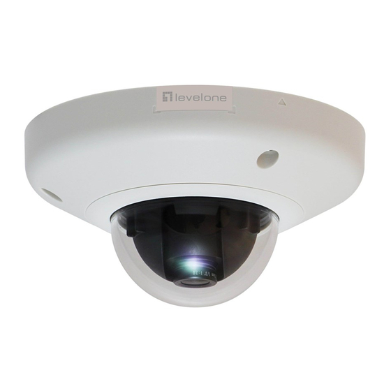
Page 10: Physical Description
Hardware Manual Physical Description FCS-3072 FCS-3093 Item Description System LEDs Indicates the camera status: Amber LED: Blinks when network activity is in progress. Blue LED: Lights up when the camera is powered up and goes off again after the boot up process is complete. - Page 11 Hardware Manual Item Description Audio Input Connects to audio input devices, such as a microphone with built-in amplifier, etc. See How to Connect Audio In Device page 23 for more information. NOTE: The microphone must have a built-in amplifier. Connecting an ordinary microphone will dwarf sounds and will result in inaudible recording.
-
Page 12: Installation Procedures
Hardware Manual Installation Procedures This section describes procedures in mounting the camera on a flat surface. NOTE: The camera images on this documentation are for reference only and may be different from the actual camera. Step 1: Prepare for Installation 1. -
Page 13: Step 2: Open The Dome Cover
Hardware Manual Step 2: Open the Dome Cover 1. Loosen the three (3) screws using the bundled hex screwdriver. 2. Lift to remove the dome cover. NOTE: The dome cover is attached to the camera body by a string, do not abruptly lift the dome cover! ... -
Page 14: Step 3: Route The Cables
Hardware Manual Step 3: Route the Cables Determine whether the cable will pass through a hole on the surface or be routed along the surface: If the cable will pass through a hole on the surface: 1. Drill the hole for the cable on the surface. Drill cable hole within this block. -
Page 15: Step 4: Install The Camera
Hardware Manual Step 4: Install the Camera 1. If necessary, insert a memory card into the memory card slot of the camera. See How to Insert the Memory Card on page 21 for more information. 2. Install the camera to the surface using the three (3) bundled screws. NOTE: Please make sure the screw is flat on the plate. -
Page 16: Step 5: Waterproof The Cable Connection
Hardware Manual Step 5: Waterproof the Cable Connection Depending on the camera model, the Ethernet cable or the “pigtail” of the camera may either have the RJ-45 connector. RJ-45 Ethernet Cable When using the RJ-45 Ethernet cable, follow the procedures below to waterproof the cable connection: 1. - Page 17 Hardware Manual 4. Make sure the bundled rubber ring is completely aligned on the gap on the gland body. 5. Attach the gland body to the Ethernet port of the camera. IMPORTANT! Make sure the rubber ring is completely aligned and flat on the gland body to avoid possible water leakage.
- Page 18 8. Attach the clamping nut to the cable gland body. Make sure the clamping nut is tightly secured and the rubber is squeezed in to avoid water leakage. DISCLAIMER: LevelOne will not be responsible for camera damage caused by water entering the cable connections.
-
Page 19: Step 6: Connect To Network
Hardware Manual Step 6: Connect to Network Connect the other end of the network cable to a switch or injector. Then, connect the switch or injector to a network or PC and a power source. See Power-over-Ethernet (PoE) example connection diagram below. Network Ethernet Cable Ethernet Cable... -
Page 20: Step 8: Close The Dome Cover
Hardware Manual Step 8: Close the Dome Cover 1. Align cable tab side of the dome cover to the direction of the network cable. 2. Tighten the three (3) screws using the supplied hex screwdriver to attach the dome cover. 3. -
Page 21: Other Adjustments And Accessories
Hardware Manual Other Adjustments and Accessories How to Install / Remove the Memory Card How to Insert the Memory Card 1. Loosen the three (3) screws to remove the dome cover. 2. Insert the memory card into the card slot with the metal contacts facing the bottom side of the camera. -
Page 22: How To Adjust The Fisheye View Orientation (For Fcs-3093 Only)22
Hardware Manual How to Adjust the Fisheye View Orientation (for FCS-3093 only) 1. Open the dome cover. 2. Loosen the three (3) screws securing the lens. 3. Turn the lens to adjust the viewing orientation. The arrow on the lens indicates the top side orientation. -
Page 23: How To Connect Audio In Device
3. If the camera is installed outdoors, be sure to wrap the audio connectors with Waterproof Tape (can be purchased in hardware stores). DISCLAIMER: LevelOne will not be responsible for camera damage due by water leakage caused by improper waterproofing of cables. -
Page 24: How To Replace The Dome Cover
Hardware Manual How to Replace the Dome Cover For more discrete surveillance needs, the pre-installed dome cover can be replaced with a smoked, vandal proof dome cover. The smoked dome cover is an optiona accessory; contact your sales agent to purchase. To replace the dome cover, follow the procedures below: 1. - Page 25 Hardware Manual 4. Remove the black rubber from the transparent dome cover and place the black rubber to the replacement dome cover. 5. Install the replacement dome cover and then the bracket. 6. Align the screw holes and secure the five (5) screws first. Take note of the screw hole which must not be screwed at this point.
- Page 26 Hardware Manual 7. Insert the screw to the eyelet of the camera hook. 8. Attach the last screw to the dome cover bracket. 9. Close the dome cover.
-
Page 27: Accessing The Camera
Hardware Manual Accessing the Camera Configure the IP Addresses In order to be able to communicate with the camera from your PC, both the camera and the PC have to be within the same network segment. In most cases, it means that they both should have very similar IP addresses, where only the last number of the IP address is different from each other. - Page 28 Hardware Manual By double-clicking with the left mouse on the camera model, it is possible to automatically launch the default browser of the PC with the IP address of the target camera filled in the address bar of the browser already. If you work with our cameras regularly, then there is even a better way to discover the cameras in the network –...
-
Page 29: Using The Default Camera Ip Address
Hardware Manual Using the Default Camera IP Address If there is no DHCP server in the given network, the user may have to assign the IP addresses to both PC and camera manually to make sure they are in the same network segment. When the camera is plugged into network and it does not detect any DHCP services, it will automatically assign itself a default IP: 192.168.0.100... - Page 30 Hardware Manual Manually adjust the IP addresses of multiple cameras: If there are more than 1 camera to be used in the same local area network and there is no DHCP server to assign unique IP addresses to each of them, all of the cameras would then have the initial IP address of 192.168.0.100, which is not a proper situation for network devices –...
-
Page 31: Access The Camera
Hardware Manual Access the Camera Now that the camera and the PC are both having their unique IP addresses and are under the same network segment, it is possible to use the Web browser of the PC to access the camera. You can use any of the browsers to access the camera, however, the full functionality is provided only for Microsoft Internet Explorer. - Page 32 Hardware Manual The following examples in this manual are based on Internet Explorer browser in order to cover all functions of the camera. Assuming that the camera’s IP address is 192.168.0.100, you can access it by opening the Web browser and typing the following address into Web browser’s address bar: http://192.168.0.100 Upon successful connection to the camera, the user interface called Web Configurator would appear together with the login page.
- Page 33 To check the firmware version through the Web Configurator, access the Setup page and click System > System Info. For further operations, please refer to the Firmware User Manual.