Table of Contents
Advertisement
Quick Links
Advertisement
Table of Contents

Related Manuals for LevelOne FCS-3071


Summary of Contents for LevelOne FCS-3071
-
Page 1: User Manual
FCS-3071 2-Megapixel PoE Dome Network Camera User Manual Ver 1.0 HW Ver: 2.0... -
Page 2: Table Of Contents
Table of Contents Overview ............................3 Features ..........................4 Package Contents ....................... 4 Dimensions ......................... 5 Connectors ......................... 6 System Requirements ........................7 Accessing Camera ........................... 8 Recording Software ......................12 Installing DC Viewer Software Online ................13 Operation & Configuration......................15 Browser-based Viewer Introduction ................ - Page 3 5.3.3.15.1 Log File ......................58 4.3.3.15.2 User Information ....................59 4.3.3.15.3 Parameters ....................... 60 4.3.3.16 Factory Default ....................61 4.3.3.17 Software Version ....................62 4.3.3.18 Software Upgrade ....................63 4.3.3.19 Maintenance ...................... 65 Streaming ......................... 66 4.4.1 Video Format (Video Resolution and Rotate Type) ..........66 4.4.2 Video Compression ....................
-
Page 4: Overview
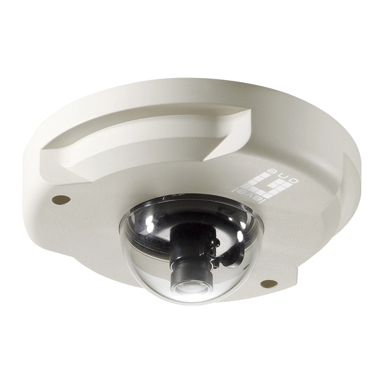
Overview The LevelOne FCS-3071 is a compact, rugged H.264 2-Megapixel PoE Mini Dome Camera designed for tough environments. The casing is tamper-resistant, it can withstand vibration, humidity, dust and fluctuating temperatures, for example in buses and trains. The FCS-3071 is a palm-sized, discreet network camera specifically designed for mass transit vehicles. -
Page 5: Features
Features Progressive Scan CMOS Sensor H.264 and MJPEG compression Motion Detection Privacy Masks Smart Picture Quality/3DNR Tampering Alarm Day/Night (ICR) Micro SD support Weatherproof (IP66 international) Micro SD support Security Torx against tampering ONVIF Support Package Contents FCS-3071 Security TorxM4 Inner Hex Wrench ... -
Page 6: Dimensions
Dimensions... -
Page 7: Connectors
Connectors The diagram below shows the IP Camera’s reset button and various connectors. Definition for each connector will be given as follows. Designation Description Reset Button Restore to default setting; press the button with a proper tool Lens Rotate the lens right/left to adjust focus Focus Fixed Screw Loosen the screw to adjust the lens Tilt Fixed Screw... -
Page 8: System Requirements
System Requirements To perform the IP Camera via web browser, please ensure your PC is in good network connection, and meet system requirements as described below. Items System Requirement 1. Intel® Pentium® M, 2.16 GHz or Personal Computer Intel® Core 2 Duo, 2.0 GHz 2. -
Page 9: Accessing Camera
Accessing Camera For initial access to the IP Camera, users can search the camera through the installer program: DeviceSearch.exe, which can be found in “DeviceSearch” folder in the supplied Device Search Software Step 1: Double click on the program Device Search.exe (see the icon below); its window will appear as shown below. - Page 10 Step 3: Click “Device Search” again, and all the finding IP devices will be listed in the page, as shown in the figure below. The IP Camera’s default IP address is: 192.168.0.250. Step 4: Double click or right click and select “Browse” to access the camera directly via web browser.
- Page 11 The default login ID and password for the Administrator are: Login ID Password root NOTE: ID and password are case sensitive. NOTE: It is strongly advised that administrator’s password be altered for the security concerns. Additionally, users can change the IP Camera’s network property, either DHCP or Static IP directly in the device finding list.
- Page 12 Step 3: Click “OK” on the Note of setting change. Wait for one minute to re-search the IP Camera. Step 4: Click the “Device Search” button to re-search all the devices. Then select the IP Camera with the correct MAC address. Double click on the IP Camera, and the login window will appear.
-
Page 13: Recording Software
Recording Software The product software CD also contains recording software- IP CamSecure, allowing simultaneous monitoring and video recording for multiple network cameras. Please install the recording software; then launch the program to add the Network Camera to the Channel list. For detailed information about how to use IP CamSecure, please refer to the user’s manual of the software or download it at http://global.level1.com. -
Page 14: Installing Dc Viewer Software Online
Installing DC Viewer Software Online For the initial access to the IP Camera, a client program, DC Viewer, will be automatically installed to your PC when connecting to the IP Camera. If the Web browser doesn’t allow DC Viewer installation, please check the Internet security settings or ActiveX controls and plug-ins settings (see Appendix A: Internet Security Settings) to continue the process. - Page 15 Once login to the IP Camera, users will see the Home page as shown below:...
-
Page 16: Operation & Configuration
Operation & Configuration The IP Camera is provided with a user-friendly browser-based configuration interface for video playback and recording. In this chapter, information about main page introduction, system related settings and camera settings will be described in detail. Browser-based Viewer Introduction There are five main tabs including <Home>, <System>, <Streaming>, <Camera>... - Page 17 System setting The administrator can set host name, system time, root password, network related settings, etc. Further details will be interpreted in chapter System. Streaming setting The administrator can modify video resolution and rotate type and select audio compression mode in this page. Camera setting Users can adjust various camera parameters, including <Exposure>, <White Balance>, <Picture Adjustment>, <Backlight>, <Digital Zoom>, <WDR Function>, <Noise Reduction>...
-
Page 18: Home Page
Home Page Click on the tab <Home> to access the Home Page. There are several function buttons on the Home page. Detailed information of each item is as described in the following chapter. 4.2.1 Function Items on Home Page Multiple Languages Support Multiple languages are supported, including German, English, French, Italian, Simplified Chinese, Traditional Chinese, Russian for the viewer window interface. - Page 19 Screen Size Adjustment Image display size can be adjusted to x1/2 and full screen. Snapshot button Click on the button and the JPEG snapshots will automatically be saved in the appointed place. The default place of saving snapshots is: C:\. To change the storage location, please refer to File Location for further details.
-
Page 20: System
System Under the tab <System>, there are submenus including: <System>, <Security>, <Network>, <DDNS>, <Mail>, <FTP>, <HTTP>, <Application>, <Motion Detection>, <Network Failure Detection>, <Tampering>, <Storage Management>, <Recording>, <File Location>, <View Information>, <Factory Default>, <Software Version>, <Software Upgrade>, and <Maintenance>. NOTE: The System configuration page is only accessible by the Administrator. 4.3.1 System The System Setting can be found under the path: System>... - Page 21 Host Name The name is for camera identification. If alarm function (refer to Application) is enabled and is set to send alarm message by Mail/FTP, the host name entered here will display in the alarm message. The maximum length of the Host Name is 30 characters. Time Zone Select the time zone you are in from the drop-down menu.
-
Page 22: Security
4.3.2 Security The Security setting can be found under this path: System> Security. Click on the Security category, there will be a drop-down menu with tabs including <User>, <HTTPS>, <IP Filter>, and <IEEE 802.1X>. 4.3.2.1 User The User setting can be found under this path: System> Security> User. Admin Password Change the administrator’s password by inputting the new password in “Admin password”... -
Page 23: Camera Control
NOTE: The following characters are valid: A-Z, a-z, 0-9, !#$%&’-.@^_~. Add user Type the new user's name and password and click on <Add> to add the new user. User name can be up to 16 characters, and the maximum length of the password is 14 characters. The new user will be displayed in the user name list. -
Page 24: Https
4.3.2.2 HTTPS The HTTPS setting can be found under this path: System> Security> HTTPS. <HTTPS> allows secure connections between the IP Camera and web browser using <Secure Socket Layer (SSL)> or <Transport Layer Security (TLS)>, which ensure camera settings or Username/ Password info from snooping. It is required to install a self-signed certificate or a CA-signed certificate for implementing <HTTPS>. - Page 25 Click on <Create> button under “Create self-signed certificate” and provide the requested information to install a self-signed certificate for the IP Camera. Please refer to the last part of this section: Provide the Certificate Information for more details. NOTE: The self-signed certificate does not provide the same high level of security as when using a CA-issued certificate.
- Page 26 State or province Enter the local administrative region. Locality Enter other geographical information. Organization Enter the name of the organization to which the entity identified in“Common Name” belongs. Organization Unit Enter the name of the organizational unit to which the entity identified in “Common Name”...
-
Page 27: Ip Filter
4.3.2.3 IP Filter The IP Filter setting can be found under this path: System> Security> IP Filter. Using the IP filter, access to the IP Camera can be restricted by denying/allowing specific IP addresses. Enable IP Filter Check the box to enable the IP Filter function. Once enabled, the listed IP addresses (IPv4) will be allowed/ denied access to the IP Camera. -
Page 28: Ieee 802.1X
The Filtered IP Addresses list box shows the currently configured IP addresses. Up to 256 IP address entries may be specified. To remove an IP address from the list, please select the IP and then click on the <Delete> button. 4.3.2.4 IEEE 802.1X The IEEE 802.1X setting can be found under this path: System>... -
Page 29: Private Key Password
The CA certificate is created by the Certification Authority for the purpose of validating itself. Upload the certificate for checking the server’s identity. Client Certificate/ Private Key Upload the Client Certificate and Private Key for authenticating the IP Camera itself. Settings ... -
Page 30: Network
4.3.3 Network The Network setting can be found under this path: System> Network. Click on the <Network> category, there will be a drop-down menu with tabs including <Basic>, <QoS>, <SNMP>, and <UPnP>. 4.3.3.1 Basic The Basic setting can be found under this path: System> Network> Basic. Users can choose to connect to the IP Camera with fixed or dynamic (DHCP) IP address. - Page 31 Get IP address automatically (DHCP) The camera’s default setting is <Use fixed IP address>. If select <Get IP address automatically>, after the IP Camera restarts, users can search it through the installer program: DeviceSearch.exe, which can be found in "DeviceSearch”...
-
Page 32: Rtsp Port
For the PPPoE users, enter the PPPoE Username and Password into the fields, and click on the <Save> button to complete the setting. Advanced Web Server port The default web server port is 80. Once the port is changed, the user must be notified the change for the connection to be successful. -
Page 33: Qos
4.3.3.2 The QoS (Quality of Service) setting can be found under this path: System> Network> QoS. QoS allows providing differentiated service levels for different types of traffic packets, which guarantees delivery of priority services especially when network congestion occurs. Adapting the Differentiated Services (DiffServ) model, traffic flows are classified and marked with DSCP (DiffServ Codepoint) values, and thus receive the corresponding forwarding treatment from DiffServ capable routers. -
Page 34: Snmp
Audio DSCP This setting is only available for the IP Cameras that support audio. Management DSCP The class consists of HTTP traffic: Web browsing. NOTE: To enable this function, please make sure the switches/ routers in the network support QoS. 4.3.3.3 SNMP The SNMP (Simple Network Management Protocol) setting can be found under this path:... - Page 35 SNMP v1/ v2 Enable SNMP v1/ v2 Select the version of SNMP to use by checking the box. Read Community Specify the community name that has read-only access to all supported SNMP objects. The default value is “public”. ...
-
Page 36: Upnp
4.3.3.4 UPnP The UPnP setting can be found under this path: System> Network> UPnP. UPnP Setting Enable UPnP When the UPnP is enabled, whenever the IP Camera is presented to the LAN, the icon of the connected IP Cameras will appear in My Network Places to allow for direct access. - Page 37 Enable UPnP port forwarding When the UPnP port forwarding is enabled, the IP Camera is allowed to open the web server port on the router automatically. NOTE: To enable this function, please make sure that your router supports UPnP and it is activated. ...
-
Page 38: Ddns
4.3.3.5 DDNS The DDNS setting can be found under this path: System> DDNS. Dynamic Domain Name System (DDNS) allows a host name to be constantly synchronized with a dynamic IP address. In other words, it allows those using a dynamic IP address to be associated to a static domain name so others can connect to it by name. - Page 39 Enter the username or e-mail required by the DDNS provider for authentication. Password/Key Enter the password or key required by the DDNS provider for authentication.
-
Page 40: Mail
4.3.3.6 Mail The Mail setting can be found under this path: System> Mail. The Administrator can send an e-mail via Simple Mail Transfer Protocol (SMTP) when event is triggered. SMTP is a protocol for sending e-mail messages between servers. SMTP is a relatively simple, text-based protocol, where one or more recipients of a message are specified and the message text is transferred. -
Page 41: Ftp
4.3.3.7 The FTP setting can be found under this path: System> FTP. The Administrator can set as sending alarm message to a specific File Transfer Protocol (FTP) site when event is triggered. Users can assign alarm message to up to two FTP sites. Enter the FTP details, which include server, server port, user name, password and remote folder, in the fields. -
Page 42: Http
4.3.3.8 HTTP The HTTP setting can be found under this path: System> HTTP. A HTTP Notification server can listen for notification messages from IP Cameras by triggered events. Enter the HTTP details, which include server name (for instance, http://192.168.0.1/admin.php), user name, and password in the fields. <Alarm> triggered and <Motion Detection>... -
Page 43: Motion Detection
4.3.3.9 Motion Detection The Motion Detection setting can be found under this path: System> Motion Detection. Motion Detection function allows detecting suspicious motion and triggering alarms when motion volume in the detected area reaches/exceeds the determined sensitivity threshold value. In the Motion Detection setting page, there is a frame (Motion Detection Window) displayed on the Live Video Pane as the figure below. - Page 44 Up 10 Motion Detection Windows can be set. Click on the <add> button under the Live Video Pane to add a Motion Detection Window. To cancel a Motion Detection Window, move the mouse cursor to the selected Window, and click on the <delete> button. If Motion Detection function is activated, the pop-off window (Motion) with indication of motion will be shown.
- Page 45 Sampling pixel interval [1-10]: The default value is 1. If the value is set as 3, it means within the detection region, system will take one sampling pixel for every 3 pixels by each row and each column (refer to the figure below). ...
- Page 46 Select <Upload for __ sec> to set the recording duration after motion event occurs. The setting range is from 1 to 99999 seconds. Select <Upload during the trigger active> to record the triggered video until the trigger is off. NOTE: Please make sure the local recording (with Micro SD/SDHC card) is activated so that this function can be implemented.
- Page 47 various parameters. When motion is detected, event images will be sent to the appointed e-mail address. <Pre-trigger buffer> function allows users to check what happened to cause the trigger. The <Pre-trigger buffer> frame rate could be pre-determined. On the other hand, <Post-trigger buffer> is for users to upload certain amount of images after the motion event occurs.
- Page 48 Add sequence number suffix (no maximum value) File name: imageXXXXXXX.jpg X: Sequence Number Add sequence number suffix up to # and then start over File Name: imageXX.jpg X: Sequence Number The file name suffix will end at the number being set. For example, if the setting is up to “10,”...
-
Page 49: Network Failure Detection
4.3.3.10 Network Failure Detection Network Failure Detection allows the IP Camera to ping another IP device (e.g. NVR, VSS, Video Server, etc.) within the network periodically and generates some actions in case of network failure occurs, for instance, a Video Server is somehow disconnected. Being capable of implementing local recording (through Micro SD card) when network failure happens, the IP Camera could be a backup recording device for the surveillance system. - Page 50 is from 1 to 99 minutes. Triggered Action (Multi-option) The Administrator can specify alarm actions that will take when network failure is detected. All options are listed as follows: Enable Alarm Output Select the item to enable alarm relay output. ...
-
Page 51: Tampering
4.3.3.11 Tampering The Tampering setting can be found under this path: System> Tampering. Tampering Alarm function helps the IP Camera against tampering such as deliberate redirection, blocking, paint spray, and lens cover, etc through video analysis and reaction to such events by sending out notifications or uploading snapshots to the specified destination(s). - Page 52 Tampering Duration Minimum Tampering Duration is the time for video analysis to determine whether camera tampering has occurred. Minimum Duration could also be interpreted as defining the Tampering threshold; longer duration represents higher threshold. Settable Tampering Duration time range is from 10 to 3600 seconds. The Default value is 20 seconds. Triggered Action (Multi-option) The Administrator can specify alarm actions that will take when tampering is detected.
- Page 53 appointed FTP site. <Pre-trigger buffer> function allows users to check what happened to cause the trigger. The <Pre-trigger buffer> frame rate could be pre-determined. On the other hand, <Post-trigger buffer> is for users to upload certain amount of images after tampering is triggered. Check the box <Continue image upload>...
- Page 54 NOTE: Make sure SMTP configuration has been completed. Refer to Mail for further details. Send HTTP notification Check this item, select the destination HTTP address, and specify the parameters for HTTP notifications. When the Tampering Alarm is triggered, the HTTP notifications can be sent to the specified HTTP server.
-
Page 55: Storage Management (Local Recording)
4.3.3.12 Storage Management (Local Recording) The Storage Management setting can be found under this path: System> Storage Management. Users can implement local recording to the Micro SD/SDHC card up to 32GB. This page shows the capacity information of the Micro SD card and a recording list with all the recording files saved on the memory card. - Page 56 When users insert the Micro SD/SDHC card, the card information such as the memory capacity and status will be shown at Device Information section. For the memory card being successfully installed, its status shall be shown at <Device information> section in the Storage Management page. Device setting Click on the <Format>...
-
Page 57: Recording (Local Recording)
4.3.3.13 Recording (Local Recording) The Recording setting can be found under this path: System> Recording. In the Recording setting page, the Micro SD Card recording schedule supports up to ten sets of time frames. User can specify the recording schedule to fit the present surveillance requirement. -
Page 58: File Location (Snapshots And Web Recording)
4.3.3.14 File Location (Snapshots and Web Recording) The File Location setting can be found under this path: System> File Location. Users can specify a storage location on the PC or in the hard drive for the snapshots and live video recording. The default setting is: C:\. Once confirm the setting, click on <Save>, and all the snapshots and web recording will be saved in the designate location. -
Page 59: View Information
4.3.3.15 View Information The View Information function can be found under this path: System> View Information. Click on the category: <View Information>, there will be a drop-down menu with tabs including <Log File>, <User Information>, and <Parameters>. 5.3.3.15.1 Log File The Log File function can be found under this path: System>... -
Page 60: User Information
4.3.3.15.2 User Information The User Information function can be found under this path: System> User Information. The Administrator can view each added user’s login information and privileges (refer to Security). Get User Information All the users in the network will be listed in the <User information> zone as shown below: User: 4321 It indicates that one user’s login username is “User”, and the password is“4321”. -
Page 61: Parameters
4.3.3.15.3 Parameters .The Parameters function can be found under this path: System> Parameter. Click on this item to view the entire system’s parameter setting such as Camera Settings, Mask Information and Network Information. -
Page 62: Factory Default
4.3.3.16 Factory Default The Factory Default setting can be found under this path: System> Factory Default. Users can follow the instructions on this page to reset the IP Camera to factory default setting if needed. Set Default Click on the <Set Default> button to recall the factory default settings. Then the system will restart in 30 seconds. -
Page 63: Software Version
4.3.3.17 Software Version The Software Version can be found under this path: System> Software Version. The current software version is displayed in the software version page. -
Page 64: Software Upgrade
4.3.3.18 Software Upgrade The Software Upgrade setting can be found under this path: System> Software Upgrade. NOTE: Make sure the upgrade software file is available before carrying out software upgrade. The procedure of software upgrade is as below: Step 1. Click on “Browse” and select the binary file to be uploaded, ex. uImage_userland. NOTE: Do not change the upgrade file name, or the system will fail to find the file. - Page 65 exists or not first, and then begin to upload the upgrade file. Subsequently, the upgrade status bar will display on the page. When it runs to 100%, the upgrade process is finished. After the upgrade process is finished, the viewer will return to Home page. Step 4.
-
Page 66: Maintenance
4.3.3.19 Maintenance The Maintenance setting can be found under this path: System> Maintenance. Users can export configuration files to a specified location and retrieve data by uploading an existing configuration file to the IP Camera. Export Users can save the system settings by exporting the configuration file (.bin) to a specified location for future use. -
Page 67: Streaming
Streaming Under the tab <Streaming>, there are submenus including: <Video Format>, <Video Compression>, <Video ROI>, <Video OCX Protocol>, <Video Frame Rate>, <Video Mask>, and <Audio>. In the Streaming submenus, the Administrator can configure specific video resolution, video compression mode, video protocol, audio transmission mode, etc. Further details of these settings will be specified in the following sections. - Page 68 Text Overlay Settings Users can select the items to display data including date/time/text on the live video panel. The maximum length of the string is 20 alphanumeric characters. Click on <Save> to confirm the Text Overlay setting. Video Rotate Type Users can change video display type if necessary.
-
Page 69: Video Compression
NOTE: Please make sure the higher compression ratio is supported by system before setup. 4.4.2 Video Compression The Video Compression setting can be found under this path: Streaming> Video Compression. Users can select a proper MJPEG/H.264 compression mode in the video compression page depending on the application. - Page 70 the setting range for H.264-1 is from 64 to 8192 kbps and for H.264-2/ H.264-3/ /H.264-4 is from 64 to 2048 kbit/s. Display Compression Information Users can also decide whether to display compression information on the Home page. CBR Mode Setting The CBR (Constant Bit Rate) mode could be the preferred bit rate mode if the bandwidth available is limited.
-
Page 71: Video Roi
4.4.3 Video ROI The Video ROI setting can be found under this path: Streaming> Video ROI. ROI stands for Region of Interest. This function allows users to select specific monitoring region for 2nd, 3rd and 4th streams, instead of showing the full image. NOTE: This function is only available when triple streams or above is selected under Video Resolution in Video Format Setting. - Page 72 Check the box and Stream 3 ROI Window will be displayed. To change the size of Stream 3 ROI Window, move the mouse cursor to the edge of the frame and draw it outward/inward. Moving the mouse to the center of the frame can shift the frame to the intended location.
-
Page 73: Video Ocx Protocol
4.4.4 Video OCX Protocol The Video OCX Protocol setting can be found under this path: Streaming> Video OCX Protocol. In the Video OCX protocol setting page, users can select RTP over UDP, RTP over RTSP (TCP), RTSP over HTTP or MJPEG over HTTP for streaming video over the network. In the case of multicast networking, users can select the Multicast mode. -
Page 74: Video Frame Rate
4.4.5 Video Frame Rate The Video Frame Rate setting can be found under this path: Streaming> Video Frame Rate. Video frame rate is for setting the frames per second (fps) if necessary. MJPEG/ H.264-1/ H.264-2/ H.264-3/ H.264-4 Frame Rate The default setting of MJPEG/H.264-1/H.264-2/ H.264-3/ H.264-4 Frame Rate is 30 fps; the setting range is from 1 to 30. -
Page 75: Video Mask
4.4.6 Video Mask The Video Mask setting can be found under this path: Streaming> Video Mask. Active Mask Function Add a Mask Check a Video Mask checkbox, and a red frame will come out in the Live Video panel at the right side. -
Page 76: Mask Color
Mask color The selections of Mask color include red, black, white, yellow, green, blue, cyan, and magenta. Click on <Save> to confirm the setting. -
Page 77: Camera
Camera Under the tab <Camera>, there are submenus including: <Exposure>, <White Balance>, <Picture Adjustment>, <Backlight>, <Digital Zoom>, <IR Function>, <WDR Function>, <Noise Reduction>, and <TV System>. -
Page 78: Exposure Setting
4.5.1 Exposure Setting The Exposure Setting can be found under this path: Camera> Exposure. The exposure is the amount of light received by the image sensor and is determined by the width of lens diaphragm opening, the amount of exposure by the sensor (shutter speed) and other exposure parameters. -
Page 79: White Balance Setting
4.5.2 White Balance Setting The White Balance Setting can be found under this path: Camera> White Balance. A camera needs to find reference color temperature, which is a way of measuring the quality of a light source, for calculating all the other colors. The unit for measuring this ratio is in degree Kelvin (K). -
Page 80: Picture Adjustment
4.5.3 Picture Adjustment The Picture Adjustment can be found under this path: Camera> Picture Adjustment. Brightness Users can adjust the image’s brightness by adjusting the item. Please select ranging from -12 to +13. To increase video brightness, select a bigger number. Click on <√ > to confirm the new setting. -
Page 81: Backlight
4.3.4 Backlight The Backlight Setting can be found under this path: Camera> Backlight. The Backlight Compensation function prevents the center object from being too dark in surroundings where excessive light is behind the center object. Click on < √ > to confirm the new setting. -
Page 82: Tv System Setting
Different level options for 3D Noise Reduction (3DNR) include Low, Mid and High. Higher level of 3DNR generates relatively enhanced noise reduction. The proprietary Smart Picture Quality (SPQ) video processing method could drastically minimum motion blur and reduce noise especially in low-light environment. The combination of SPQ and 3DNR at different level further yields exceptional video performance in various conditions. -
Page 83: Appendix A: Internet Security Settings
Appendix A: Internet Security Settings If ActiveX control installation is blocked, please either set Internet security level to default or change ActiveX controls and plug-ins settings. Internet Security Level: Default Step 1: Start the Internet Explorer (IE). Step 2: Select <Tools> from the main menu of the browser. Then Click <Internet Options>. Step 3: Click the <Security>... - Page 84 Step 4: Down the page, press “Default Level” (see the figure above) and click “OK” to confirm the setting. Close the browser window, and open a new one later when accessing the IP Camera. ActiveX Controls and Plug-ins Settings Step 1~3: Refer to the previous section above. Step 4: Down the page, press “Custom Level”...
- Page 85 The Security Settings screen is displayed as below: Step 5: Under “ActiveX controls and plug-ins”, set ALL items (as listed below) to <Enable> or <Prompt>. ActiveX controls and plug-in settings: Automatic prompting for ActiveX controls Binary and scrip behaviors Download signed ActiveX controls Download using ActiveX controls Initialize and script ActiveX not marked as safe Run ActiveX controls and plug-ins...
-
Page 86: Appendix B: Dc Viewer Download Procedure
Appendix B: DC Viewer Download Procedure The procedure of DC Viewer software download is specified as follows. Step 1: In the DC Viewer installation page, click “Next” for starting installing. Step 2: Setup starts. Please wait for a while until the loading bar runs out. - Page 87 Step 3: Click “Finish” to close the DC Viewer installation page. Then, the IP Camera’s Home page will display as follows:...
-
Page 88: Appendix C: Install Upnp Components
Appendix C: Install UPnP Components Please follow the instructions below to install UPnP components. Step 1: Go to “Start”, click on “Control Panel”, and then double click “Add or Remove Programs”. Step 2: Click on “Add/Remove Windows Components” in the Add or Remove Programs page.. - Page 89 Step 3: Select “Networking Services” from the Components list in the Windows Components Wizard window, and then click “Details”. Step 4: Select “UPnP User Interface” in the Networking Services’ subcomponents list and then click “OK”.
- Page 90 Step 5: Click “Next” in the Windows Components Wizard page. Step 6: Click “Finish” to complete installation.