Table of Contents
Advertisement
Quick Links
Download this manual
See also:
Instruction Manual
HD IP PTZ CAMERA
VN-H657U
Specifications and appearance of this unit are subject to change for further improvement without prior
notice.
This manual does not contain descriptions such as those on "Setting Using Internet Explorer" and "Built-
in Viewer Operation". For more details on the settings and operation, please read through
"INSTRUCTIONS" on the CD-ROM.
Please check the latest version of the INSTRUCTIONS from the following Mobile User Guide or
download the PDF from the URL below.
Mobile User Guide
When you are outside, you can refer to the instructions from your Android or iPhone.
http://manual3.jvckenwood.com/pro/mobile/global/
You can view the Mobile User Guide using the browser on your Android phone or
iPhone.
For Customer Use:
Enter below the Serial No. which is located
on the body.
Retain this information for future reference.
Model No.
Serial No.
INSTRUCTIONS
Please read the following before getting started:
Thank you for purchasing this product.
Before operating this unit, please read the
instructions carefully to ensure the best
possible performance.
LST1490-001A
Advertisement
Table of Contents

Related Manuals for JVC VN-H657U


Summary of Contents for JVC VN-H657U
- Page 1 HD IP PTZ CAMERA VN-H657U INSTRUCTIONS Specifications and appearance of this unit are subject to change for further improvement without prior notice. This manual does not contain descriptions such as those on “Setting Using Internet Explorer” and “Built- in Viewer Operation”. For more details on the settings and operation, please read through “INSTRUCTIONS”...
-
Page 2: Safety Precautions
Safety Precautions Slots and openings in the cabinet and the back or bottom are provided for ventilation, and to insure reliable IMPORTANT SAFEGUARDS operation of the appliance and to protect it from overheating, these Read all of these instructions. openings must not be blocked or Save these instructions for later use. - Page 3 Do not attempt to service this FOR USA AND CANADA appliance yourself as opening or removing covers may expose you to CAUTION dangerous voltage or other hazards. Refer all servicing to qualified service RISK OF ELECTRIC SHOCK personnel. DO NOT OPEN Unplug this appliance from the wall outlet and refer servicing to qualified CAUTION:...
- Page 4 This device complies with part 15 of the TO REDUCE THE RISK OF FIRE OR FCC Rules. Changes or modifications ELECTRIC SHOCK, DO NOT not approved by JVC KENWOOD could EXPOSE THIS APPLIANCE TO RAIN void the user's authority to operate the OR MOISTURE.
- Page 5 European representative of recovery and recycling in European JVC KENWOOD Corporation is: accordance with your national Union. JVC Technical Services Europe GmbH legislation. By disposing of this Postfach 10 05 04 product correctly, you will help 61145 Friedberg to conserve natural resources...
- Page 6 This unit is able to divert lightning Consult your dealer as special conduction to itself and the connecting technique is required when cables to a certain extent but this is not installing this product. Ensure that 100 % guaranteed. For installation the fixing screws or nuts are locations that are likely to suffer tightened securely, otherwise, the...
-
Page 7: Table Of Contents
Contents Operation Built-in Viewer Operation ......... 53 Built-in Viewer Screen Configuration ....53 Getting Started [Control] ............55 Safety Precautions ..........2 [Image Settings] Settings ......55 Contents ............7 [PTZ Settings] ..........57 Features ............8 [PTZ Control] ..........59 Precautions ............ -
Page 8: Contents
The supplied CD-ROM contains and 3D noise reduction to prevent the screen from “INSTRUCTIONS” (this manual), “API Guide” appearing grainy, thereby achieving high picture (pdf), “JVC-VN-SearchTool”, “JVC-VN-IP quality in low illuminance. Settings Tool”, and “README” (txt). It supports the 1080P (1920x1080) Full HD Symbols used in this manual resolution. -
Page 9: Precautions
Storage and Operating Environment When attaching the ceiling mount section to the VN-H657U is an indoor camera. It cannot be used camera unit before transporting, pull out the tip outdoors. of the fall prevention wire to prevent it from being VN-H657U is a pendant mount camera. - Page 10 Copyright Protection Auto Focus With the exception of the user being the Auto Focus operation can be performed on this copyright holder or when permission such as for product after the PTZ (pan/tilt/zoom) operation duplication has been granted by the copyright stops.
- Page 11 unclear. In this case, you can avoid shooting the Others above area by using the Tilt Limit settings. This camera will perform the initial operation of (A P44 [ Tilt Limit ] ) pan/tilt/zoom upon powering on. It takes about When shooting objects with a luminance 90 seconds before the initial operation starts.
-
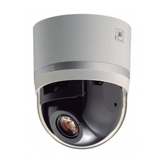
Page 12: Accessories
Accessories Name of Parts Before mounting this product, please check to VN-H657U ensure that all the following accessories and attachments are available. Camera INSTRUCTIONS (Installation/IP Address Settings): 1 Warranty Card (for USA): 1 Template: 1 CD-ROM: 1 Wire Clamp: 1... - Page 13 H Fixing holes (x3) Note : This hole is for mounting the ceiling clamping Do not peel off the protective sheet which is bracket to the ceiling or the ceiling recessed attached at shipment, until the dome cover is bracket (WB-S685U: Sold separately). mounted on the main unit.
-
Page 14: Alarm Input/Output Signal
Alarm Input/Output Signal Alarm Output Signal Connect to alarm devices such as alarm, indicator, light or buzzer. Alarm Input Signal Alarm output signal is an open collector output insulated with photo coupler. Connect to sensors such as infrared sensors, door sensors, metal sensors and manual switches. -
Page 15: Operating Environment
Operating Environment Network Ensure that there is sufficient network Recommended Computer bandwidth for the data volume to be sent out by Specifications the camera. Do not send multicast stream that : Windows 7 Professional (SP1), exceeds the bandwidth. If the entire bandwidth Windows XP Professional, or is used by the multicast stream, control of this Home Edition (SP3) - Page 16 Bit Rate of H.264 Stream List of Protocols and Port Numbers Used by Camera You can select either the Variable Bit Rate (VBR) or Constant Bit Rate (CBR) system for H.264 The camera uses the protocols and port numbers stream. listed below.
-
Page 17: Images
Images Uploading and Downloading of the Language File You can change the language on settings page and H.264 Profiles “Built-in Viewer” of the camera. The camera supports both the H.264 Baseline Profile and H.264 High Profile standards. Procedure High Profiles can maintain high image quality with 1 Open the Settings page. -
Page 18: Settings
Settings] camera. The factory settings are as follows. [Encoding] admin [Alarm] All operations and setting changes are allowed. [Alarm Environment] (Default Password: “jvc”) [PTZ] operator The following items cannot be operated, and [Network] setting changes are not permitted. [Basic [Protocol]... -
Page 19: Installation And Connection Preparations
Installation and B Push the lock knobs inward from both the left Connection Preparations and right directions as indicated by the two arrows. (If the camera fixing lock knob is too stiff, push Be sure to put on protective glasses to protect your the knob hard while pressing the edge of the eyes from falling objects when mounting the camera unit (A in the diagram) against the table... - Page 20 Length of 100 m or shorter duplication. Set up an IP address by either using Category 5e and above the JVC-VN-IP SettingTool (included on the supplied CD-ROM) or turning the power supply of each camera on separately to avoid duplication.
- Page 21 7 Connect the alarm signal cable to the 8 After connection of the cables is alarm signal terminal. complete, bundle them with a wire clamp (supplied). Connect the alarm signal input/output terminal to external devices, such as a sensor or buzzer. Wire clamp fixing For information on the pin number and signal hole...
-
Page 22: Mounting The Camera
Mounting the Camera 2 Remove the tape, lens cap, and packing sheet from the lens section of the camera. 1 With the FRONT mark (D) facing the shooting direction, secure the ceiling 3 Mount the dome cover on the main unit mount section to the ceiling. - Page 23 4 Mount the fall prevention wire to the 6 Lock the camera fixing lock knobs (x2) camera (for connecting the ceiling When the camera is mounted on the ceiling mount section, lower the camera fixing lock mount section to the camera). knobs (x2) in the direction of the arrow and Mount the fall prevention wire, which is secure the camera such that it does not fall...
-
Page 24: Ip Address Settings
Configure the Internet Explorer settings in order duplication. Set up an IP address by either using to establish connection between the computer the JVC-VN-IP SettingTool (included on the and the camera. supplied CD-ROM) or turning the power supply of each camera on separately to avoid duplication. -
Page 25: Step2 Internet Explorer Setting
Step2 Internet Explorer Setting Select [Enable]. 1 Launch the Internet Explorer on the computer. 2 When proxy settings are enabled in the Internet Explorer, follow the steps below to disable the proxy of the Internet Explorer. A Select in the sequence of [Tools]-[Internet 4 If ActiveX controls and plug-ins of Options]-[Connections]-[LAN Settings]. -
Page 26: Step3 Connecting The Camera To The Computer
[YES] button to proceed. 2 Enter the user name and password (login as “admin”). A Enter the user name. (default password is “admin”) B Enter a password. (default password is “jvc”) C Click OK. Step2 Internet Explorer Setting... -
Page 27: Step4 Ip Address Setting For The Camera
IP address. Access the [TOOL_E] folder of the supplied CD-ROM disk, and search for the camera in the LAN using the “JVC-VN-SearchTool” of this folder. * For the [JVC-VN-SearchTool] details, please open the “README” file in the [TOOL_E] folder. -
Page 28: Step4 Ip Address Setting For The Camera
B Select [Time Zone]. C Click to confirm. Memo : For information on the network settings, please consult your network administrator. If you enter the following URL directly into the address bar of Internet Explorer, you can open the [Basic Setting1] page after logging in as “admin”... -
Page 29: How To Open The Settings Page
- [Encoding] (*2) ........P 37 - [Alarm] (*2) ..........P 40 2 Enter the user name and password. The factory default is “admin” and “jvc”. - [Alarm Environment] (*2) ......P 42 After entering a correct user name and password, the Built-in Viewer of the camera - [Alarm Output] ........ -
Page 30: [Basic Setting1] Page
[Basic Setting1] Page 9 Default Gateway Sets the default gateway of camera. Enter 0.0.0.0 if you do not want to set a default This page is for performing basic setting related to gateway. the network. [Factory default: R0.0.0.0] This page can be used during access using “admin”. -
Page 31: [Basic Setting2] Page
[Basic Setting2] Page 9 Scenefile You can select the setting that is suitable for the shooting scene. You can select the following eight This page sets fundamental camera and encoding scenes. You can customize the camera page parameters. This page can be used during access settings (except Camera ID) stored in “Scenefile”. - Page 32 Encode Select the frame size for each screen of JPEG and H.264 from the following six patterns. o Selectable distribution size H.264 High 1920´1080 30 fps (Frame size: 1920´1080, frame rate: 30 fps, communication speed: 8 Mbps, bit rate: CBR, I Frame Interval: 30 frames) H.264 High 1920´1080 5 fps (Frame size: 1920´1080, frame rate: 5 fps,...
-
Page 33: [Advanced Settings] Page
[Advanced Settings] Page Memo : You can enter up to 40 characters consisting of alphabets (both upper case and lower case), [Camera] Page numerals, parentheses, commas, periods, spaces and hyphens. This page sets the camera’s parameters. Settings All characters entered in the JPEG comment here are linked to the Camera items in the [Basic segment will be saved, but some characters Setting2] page. - Page 34 Iris Memo : With a moving object, the higher the noise You can set the convergence level for auto iris. reduction (as you select LowNMidNHigh), the Auto +1: Converges to a level brighter than more likely there will be an afterimage. “Auto”...
- Page 35 9 AWC B-Gain 9 Priority Sets the gain of B (blue) when in the AWC mode. Sets the priority of ALC (function for maintaining the A larger value increases the blueness and a smaller video level according to the object brightness). value decreases the blueness.
- Page 36 Day/Night Back Light Compensation Sets video to Black & White mode. Also allows you Set this feature when there is a bright light source to select from among 3 levels for automatically in the same direction as the object. Enables activating Black &...
-
Page 37: [Encoding] Page
When “Single-Encode” is selected in [Encode] [Encoding] Page Enables only Encoder No.1 out of the three This page sets the JPEG/H.264 encoding channels of encoders. parameters. Settings here are linked to the [Encode] item of [Basic Setting2] page. (A P31 [[Basic Setting2] Page] ) This page can be used during access using “admin”... - Page 38 VBR: When “Multi-Encode” is selected in [Encode] The bit rate varies according to the condition of Each of the three channels of the encoder can be input video signals. The picture quality is stable set to H.264 High, H.264 Baseline or JPEG, and a but it is difficult to estimate the bit rate.
- Page 39 9 Framesize 9 Quality (when “JPEG” is selected) Select the frame size of each JPEG or H.264 Selects the JPEG picture quality (scalable rate screen. control method) and picture quality level. [Encoder No.1 settings: R1920´1080, 1280´960, AFS: 1280´720, 720´480, 640´480, 640´360, Encoding is performed such that the target file size is the average size of multiple JPEG 352´240, 320´240]...
-
Page 40: [Alarm] Page
[Alarm] Page Action Selects the action to perform when the alarm is This page sets the actions to be taken if an alarm activated. occurs. You can set up to five actions (No. 1 to No. Disable: Performs no action. This page can be used during access using TCP: “admin”... - Page 41 Max. Interval Switch Scene File This is available when both [1st Trigger] and [2nd Scene File: Select the scene file to change. For details of the Trigger] are set. scene file, see the [Camera] page. Specify the maximum interval between each (A P33 [[Camera] Page] ) trigger for [1st Trigger] and [2nd Trigger].
-
Page 42: [Alarm Environment] Page
[Alarm Environment] Page Alarm Output Configure settings related to alarm output from an This page sets up the alarm environment. alarm output cable or connector. This page can be used during access using “admin” or “operator”. 9 Duration Click [Advanced Settings] in the side menu, and Set the output duration for [Manual Output]. -
Page 43: [Ptz] Page
[PTZ] Page 9 Pan Limit This item sets the movable range of the pan This page allows you to specify the Move Preset (horizontal) operation during manual operation Position and Auto Flip settings. when “ON” is selected. It is invalid when “OFF” is This page can be used during access using selected. - Page 44 Mode1: 9 Tilt Limit When the camera faces bottom, it rotates 180° This item sets the movable range of the tilt (vertical) horizontally and stops. In this case, the operation during manual operation. operating direction of the camera is the same as When this item is set to 10°, the movable range of that of the Pan/Tilt operation.
-
Page 45: [Network] Page
[Network] Page 9 IP Address Sets the IP address of camera. This page sets the network settings. [Factory default: 192.168.0.2] This page can be used during access using “admin”. 9 Subnet Mask Click [Network] in the side menu. Sets the subnet mask of camera. Press the [OK] button to enable the new [Factory default: 255.255.255.0] settings. -
Page 46: [Protocol] Page
[Protocol] Page Protocol Settings Sets the protocols. This page sets the protocol. This page can be used during access using 9 HTTP Server Port “admin”. You can change the port number for the built-in Memo : HTTP server of the camera. Press the [OK] button to enable the new [Set values: 1 to R80 to 65535] settings. -
Page 47: [Time] Page
[Time] Page [Password] Page This page sets the current clock time. This page sets a password. This page can be used during access using This page can be used during access using “admin”. “admin”. Press the [OK] button to enable the new Note : settings. -
Page 48: [Maintenance] Page
[Maintenance] Page Memo : Executing update does not reset the camera This page maintains the camera system. settings. This page can be used during access using Note : “admin”. Do not shut down the system and computer Click [Advanced Settings] in the side menu, and power supplies when the firmware is being click [Maintenance]. -
Page 49: [Miscellaneous] Page
[Operation] Page Auto Cleaning This page displays the operation status of the 9 Auto Cleaning camera. You can set whether to automatically clean the This page can be used during access using power and signal transmission components. “admin” or “operator”. Setting to “ON”... -
Page 50: [Settings] Page
[Settings] Page [Position List] Page Displays the firmware version and the current Displays the preset position information. settings of the camera. This page can be used during access using This page can be used during access using “admin” or “operator”. “admin”... -
Page 51: List Of Factory Defaults Of Each Page
List of Factory Defaults of Alarm Page Each Page Item Factory Settings Action Disable 1st Trigger Pin Input1 Make Camera Page Max. Interval Item Factory Settings 2nd Trigger Disable Camera ID Camera ID model Action Position Number(*1) (VN-H657) TCP IP Address(*2) Scenefile General TCP Port Number(*2) - Page 52 Factory Settings Time Zone (GMT) UTC Password Page Item Factory Settings Password Displayed as ***. Default passwords are: admin: jvc operator: jvc user: jvc Password Re-Input Maintenance Page Item Factory Settings Auto Cleaning Auto Cleaning Time 00 h 00 m...
-
Page 53: Built-In Viewer Operation
Built-in Viewer Operation Built-in Viewer Screen Configuration The camera comes with a Built-in Viewer. Enter the IP address of the camera in the address bar of Internet Explorer to start up the Built-in Memo : Viewer. The Built-in Viewer enables operations Built-in Viewer settings are stored in cookies. - Page 54 Viewer Setup Display Size Switches the Operation Menu to the Viewer Setup Sets a display size of image area. Menu. Fixed: Click this button when you want to configure the Sets the image display size to the same as the settings of [Unicast], [On Screen Display] and preset frame size.
-
Page 55: [Control]
[Control] White Balance 9 Mode [Image Settings] Settings ATW-Wide: Switches to the Auto-Tracking White Balance Adjusts the picture quality. (automatic color temperature tracking) Wide This page can be used during access using mode. Adjusts the white balance automatically “admin” or “operator”. according to the color temperature of the light. - Page 56 Iris Day/Night The iris is adjusted automatically. You can also set Sets video to Black & White mode. Also allows you exposure compensation to ±1 with respect to the to select from among 3 levels for automatically auto adjustment value. activating Black &...
-
Page 57: [Ptz Settings]
[PTZ Settings] This page can be used during access using “admin” or “operator”. While another menu is open, click [Control] to switch to the Control Menu. Click [PTZ Settings] to open the Settings screen. Preset Position Sets the camera preset position. When [Auto Flip] is set to “Digital Flip”, preset positions cannot be registered when the tilt angle is more than 90 degrees. - Page 58 Auto Pan Mode Select the [Mode] of the auto pan operation. Right: Rotate the camera horizontally in the right direction from the [Start]. Left: Rotate the camera horizontally in the left direction from the [Start]. Return: Move between [Start] and [Return] in the clockwise direction from the [Start] toward the [Return].
-
Page 59: [Ptz Control]
[PTZ Control] Pan / Tilt / Zoom Pan / Tilt operation: Controls the PTZ function. Operate the camera to Click the arrow buttons to move the display area adjust the direction, angle and focus. in the direction indicated by the arrow. Release This page can be used during access using the button to stop the movement. - Page 60 Auto Function Pan / Tilt / Zoom Select the operations. Pan / Tilt operation: Only “Auto Pan” can be selected. Click the arrow buttons to move the display area in the direction indicated by the arrow. Release [Start] button: the button to stop the movement. Start the selected Auto function.
-
Page 61: [Viewer Setup]
[Viewer Setup] HTTP Port You can change the port number to be used when the client computer accesses to the camera via [Unicast] Settings HTTP. Specify the same value as the parameter being set You can set the HTTP port and the JPEG frame rate on the camera’s Protocol Page. -
Page 62: [On Screen Display] Settings
[On Screen Display] Settings Camera ID When “ON” is selected, the [Camera ID] is Sets a display item on the viewer screen. For the Built-in Viewer, characters are displayed as displayed at the top of the screen. overlay on the video image. You can set the [Camera ID] from the camera’s This page can be used during access using [Basic Setting2] or [Camera] Page. -
Page 63: [Other] Settings
Exiting Built-in Viewer [Other] Settings When you are using the JPEG data compression, you can record still images. Click the [´] button at the right top corner of the You can rename the folder which stores a captured window to exit the viewer. file. -
Page 64: Troubleshooting
N If you have a computer connected to the same N Set the HTTP port value for the Built-in Viewer LAN, search for the IP address using “JVC- to the same value specified for the HTTP VN-SearchTool” on the computer. - Page 65 When I install the Built-in Viewer, A white zone appears in the Built-in Viewer. authentication by VeriSign appears. If you set up Internet Explorer as follows, some The Built-in Viewer has an electronic signature for Internet Explorer graphics may not appear and authentication by VeriSign.
-
Page 66: Consumable Parts
Consumable Parts Videos set to be exported are not saved to my computer. The following are consumable parts. They must be N Run the Internet Explorer as an administrator. replaced once they reach their lifetime. You can perform this as follows. The lifetime is only an estimation and differs A Right-click Internet Explorer. -
Page 67: Appendix (Restrictions During Multi-Encoding)
Appendix (Restrictions during Multi-encoding) Possible Encoder No.1 and No.2 Setting Combinations During multi-encoding, there is a limit to the total number of pixels per unit time that can be encoded simultaneously by three encoders (total frame size and frame rate processed by each encoder). Encoder No.2 cannot be set to a frame size with a resolution higher than that of Encoder No.1. - Page 68 Encoder No.2 settings Framesize Framerate 30 - 1 30 - 1 30 - 1 30 - 1 30 - 1 1920 1080 25 - 1 1280 30 - 1 1280 30 - 1 30 - 1 30 - 1 30 - 1 30 - 1 30 - 1 : Encoder No.2 settable, Encoder No.3 setting arbitrary...
- Page 69 Restrictions when Encoder No.1 is set to 1920´1080 30 fps When Encoder No.1 is set to a frame size of 1920´1080 and a frame rate of 30 fps, Encoder No.3 will be subject to restrictions on the settable values depending on the setting of Encoder No.2.
-
Page 70: Specifications
Specifications Rotation platform Horizontal : 360 ° Endless rotation rotation range CAMERA HEAD Horizontal : Approx. 0.07 °/s to approx. Image pickup : 1/2.8" CMOS rotation speed 400 °/s device Vertical rotation : -5 ° to 185 ° (5 ° above horizontal Minimum brightness of object range level to face bottom to 5 °... -
Page 71: Specifications
Ceiling mounting hole [Unit: mm] FRONT mark Front of camera φ160 φ140 Screw Camera outer mounting diameter hole Screw mounting hole Position where cables are to be 22.5 pulled out from the side Dimension [Unit: mm] φ * Specifications and appearance of this unit are subject to change for further improvement without prior notice. - Page 72 LST1490-001A © 2013 JVC KENWOOD Corporation...