Table of Contents
Advertisement
Quick Links
Advertisement
Table of Contents

Related Manuals for Vertex Standard VXD-7200


Summary of Contents for Vertex Standard VXD-7200
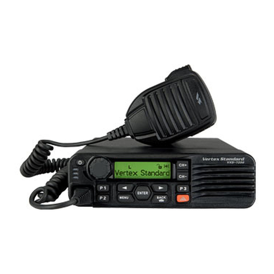
- Page 1 VXD-7200 perating anual...
-
Page 3: Declaration Of Conformity
This declaration is applicable to your radio only if your radio is labeled with the FCC logo shown below. DECLARATION OF CONFORMITY Per FCC CFR 47 Part 2 Section 2.1077(a) Name: Vertex Standard Co., Ltd. Address: US Headquarters: 10900 Walker Street, Cypress, CA 90630 U.S.A. Phone Number: 1-800-283-7839... - Page 4 Note: This equipment has been tested and found to comply with the limits for a Class B digital device, pursuant to part 15 of the FCC Rules. These limits are designed to provide reasonable protection against harmful interference in a residential installation. This equipment generates, uses and can radi- ate radio frequency energy and, if not installed and used in accordance with the instructions, may cause harmful interference to radio communications.
-
Page 5: Table Of Contents
Display Icons ..........24 This User Guide contains all the information you Call Icons ............25 need to use the Vertex Standard VXD-7200 Digital Sent Item Icons ..........26 Two-Way Radio System. LED Indicators ..........26 Audio Tones ............ 27 Product Safety and RF Energy Exposure .. - Page 6 Advanced Features ........... 38 Assigning Ring Styles........ 50 Radio Check ........... 38 Escalating Alarm Tone Volume ....50 Sending a Radio Check......38 Call Log Features ........... 51 Remote Monitor ..........40 Viewing Recent Calls ........ 51 Initiating Remote Monitor ......40 Missed Call Screen ........
- Page 7 Viewing a Saved Text Message ... 61 Utilities ............72 Deleting a Saved Text Message Setting the Squelch Level......72 from Drafts ........... 62 Setting the Power Level ......73 Managing Fail-to-Send Text Messages ..62 Turning the Voice Operating Transmission Resending a Text Message ....
-
Page 8: Product Safety And Rf Energy Exposure
These recommended RF exposure levels include substantial margins of protec- tion. All Vertex Standard 2-way radios are designed, manufactured, and tested to ensure they meet government- established RF exposure levels. In addition, manufacturers also recommend specific operating instructions... - Page 9 RF exposure and to satisfy compliance requirements. Compliance with RF Exposure Standard Your Vertex Standard two-way radio is designed and tested to comply with a number of national and interna- tional standards and guidelines (listed below) regarding human exposure to radio frequency electromagnetic energy.
- Page 10 Your Vertex Standard two-way radio complies with the following RF energy exposure standards and guidelines: Ÿ United States Federal Communications Commission, Code of Federal Regulations; 47CFR part 2 sub- part J Ÿ American National Standards Institute (ANSI) / Institute of Electrical and Electronic Engineers (IEEE) C95.
- Page 11 See the co-located transmitter’s user manual for more details. NOTE: If you are not sure of the rated power of your radio, contact your Vertex Standard representative or dealer and supply the radio model number found on the radio model label. If you can not determine the rated power out, then assure 3-feet separation from the body of the vehicle.
- Page 12 RF Safety Standards. Approved Accessories Ÿ This radio has been tested and meets RF Safety Standards when used with the Vertex Standard acces- sories supplied or designated for this product. Use of other accessories may result in non-compliance with RF Safety Standards.
- Page 13 Compliance and Control Guidelines and Operating Instructions for Mobile Two-Way Radios Installed as Fixed Site Control Stations If mobile radio equipment is installed at a fixed location and operated as a control station or as a fixed unit, the antenna installation must comply with the following requirements in order to ensure optimal performance and compliance with the RF energy exposure limits in the standards and guidelines listed on page 4: Ÿ...
- Page 14 Vehicles To avoid possible interaction between the radio transmitter and any vehicle electronic control modules, such as ABS, engine, or transmission controls, the radio should be installed only by an experienced installer and the following precautions should be used when installing the radio: 1.
- Page 15 Operational Warnings For Vehicles with an Air Bag Do not mount or place a mobile radio in the area over an air bag or in the air bag deployment area. Air bags inflate with great force. If a radio is placed in the air bag deployment area and the air bag inflates, the radio may be propelled with great force and cause serious injury to occupants of the vehicle.
-
Page 16: Important Safety Information
Check with your dealer or system administrator for This radio is restricted to occupational use only more details of all the features supported. to satisfy FCC RF energy exposure require- ments. For a list of Vertex Standard-approved antennas, batteries, and other accessories, visit the following website: http://www.vertexstandard.com/lmr... -
Page 17: Computer Software Copyrights
The Vertex Standard products described in this rights including patent rights, copyrights and trade manual may include copyrighted Vertex Standard secrets of Digital Voice Systems, Inc. computer programs stored in semiconductor mem- This voice coding Technology is licensed solely for ories or other media. -
Page 18: Getting Started
What optional accessories may suit your This User Guide covers the basic operation of the needs? Vertex Standard Mobile. However, your dealer or system administrator may have customized your radio for your specific needs. Check with your dealer or system administrator for more information. -
Page 19: Powering Up The Radio
NOTE: There is no power up tone if the radio Powering Up the Radio tones/alerts function is disabled (see Turn- Press the On/Off Button briefly. ing the Radio Tones/ Alerts On or Off on The green LED blinks and the Home screen lights page 76). -
Page 20: Identifying Radio Controls
Dentifying aDio ontrols Take a moment to review the following: Radio Controls ..........page 18 VXD-7200 Programmable Buttons ....... page 19 Accessing the Programmed Functions ..page 21 Push-To-Talk (PTT) Button ......page 22 ENTER MENU BACK Switching Between Conventional Analog and Digital Mode......... -
Page 21: Programmable Buttons
Ext PA On/Off – Toggles the audio routing between Programmable Buttons the connected public address (PA) loudspeaker Your dealer can program the programmable but- amplifier and the radio’s internal public address (PA) tons as shortcuts to radio functions or up to a system. -
Page 22: Assignable Settings Or Utility Functions
1 Assignable Settings or Utility Functions Radio Enable – Allows a target radio to be re- motely enabled. All Tones/Alerts – Toggles all tones and alerts on Radio Disable – Allows a target radio to be re- or off. motely disabled. Backlight –... -
Page 23: Accessing The Programmed Functions
Accessing the Programmed Functions You can access various radio functions through one of the following ways: • A short or long press of the relevant program- ENTER mable buttons. BACK MENU • Use the Menu Navigation Buttons as follows: 1 To access the menu, press the button. -
Page 24: Push-To-Talk (Ptt) Button
If the Talk Permit Tone (see Turning the Talk Per- Push-To-Talk ( PTT ) Button mit Tone On or Off on page 77) or the PTT Sid- The PTT button on the side of the microphone etone is enabled, wait until the short alert tone serves two basic purposes: ends before talking. -
Page 25: Switching Between Conventional Analog
Switching Between Conventional Analog and Digital Mode Channel Rocker Each channel in your radio can be configured as a conventional analog or conventional digital chan- nel. Use the Channel Rocker to switch between an analog or a digital channel. When switching from digital to analog mode, cer- tain features are unavailable. -
Page 26: Identifying Status Indicators
Power Level Dentifying tatus nDicators Radio is set at Low power. Your radio indicates its operational status through the following: Radio is set at High power. Display Icons ..........page 24 Tones Disable Call Icons ............ page 25 Tones are turned off. Sent Item Icons........... -
Page 27: Call Icons
Talkaround Call Icons In the absence of a repeater, radio is cur- The following icons appear on the radio’s display rently configured for direct radio to radio during a call. communication. These icons also appear in the Contacts list to indi- cate ID type. -
Page 28: Sent Item Icons
Sent Item Icons LED Indicator The following icons appear at the top right corner LED indicator shows the operational status of your of the radio’s display in the Sent Items folder. radio. Sent Successfully The text message is sent successfully. Send Failed The text message cannot be sent. -
Page 29: Audio Tones
Rapidly blinking green – Radio is receiving a Audio Tones privacy-enabled call or data Alert tones provide you with audible indications of NOTE: While in conventional mode, when the the radio’s status or the radio’s response to data green LED blinks, it indicates the radio de- received. -
Page 30: Receiving And Making Calls
A zone is a group of channels. Your radio supports Once you understand how your Vertex Standard up to 250 zones, with a maximum of 160 channels Mobile is configured, you are ready to use your ra- per zone. -
Page 31: Selecting A Radio Channel, Subscriber Alias Or Id, Or Group Alias Or Id
Selecting a Radio Channel, Subscriber Alias ID, or Group Alias or ID Procedure: Channel Rocker Once the required zone is displayed (if you have multiple zones in your radio), press the Channel Rocker to select the channel, sub- scriber alias or ID, or group alias or ID. Press the programmed One Touch Access button to select the preset channel assigned to the button. -
Page 32: Receiving And Responding To A Radio Call
1 Receiving and Responding to a Group Call Receiving and Responding to a Radio Call Once the channel, subscriber alias or ID, or group To receive a call from a group of users, your radio alias or ID is displayed, you can proceed to receive must be configured as part of that group. -
Page 33: Receiving And Responding To A Private Call
5 Wait for the Talk Permit Tone to finish (if en- Only one of these call types can be programmed abled) and speak clearly into the microphone. to your radio by your dealer. Procedure: Wait for the PTT Sidetone to finish (if en- When you receive a Private Call: abled) and speak clearly into the microphone. -
Page 34: Receiving An All Call
1 Receiving an All Call Making a Radio Call An All Call is a call from an individual radio to every You can select a channel, subscriber alias or ID, or radio on the channel. It is used to make important group alias or ID by using: announcements requiring the user’s full attention. -
Page 35: Making A Call With The Channel Rocker
1 Making a Call with the Channel Rocker If there is no voice activity for a predetermined period of time, the call ends. 1 Making a Group Call 7 Radio returns to the screen you were on prior to To make a call to a group of users, your radio must initiating the call. -
Page 36: Making An All Call
2 Press the PTT button to make the call. The 1 Making an All Call green LED lights up. The first line displays the This feature allows you to transmit to all users on subscriber alias or ID. The second line displays the channel. -
Page 37: Making A Group Or Private Call With The One Touch Access Button
1 Making a Group or Private Call with the One 5 If the Channel Free Indication feature is en- abled, you will hear a short alert tone the mo- Touch Access Button ment the target radio releases the PTT button, The One Touch Access feature allows you to make indicating the channel is free for you to re- a Group or Private Call to a predefined alias or ID... -
Page 38: Talkaround
7 The display shows “Talkaround On”. Talkaround You can continue to communicate when your re- The display shows “Talkaround Off”. peater is not operating, or when your radio is out 8 The screen automatically returns to the previ- of the repeater’s range but within talking range of ous menu. -
Page 39: Permanent Monitor
Permanent Monitor Use the Permanent Monitor feature to continuously monitor a selected channel for activity. Procedure: 1 Press the programmed Permanent Monitor button. 2 Radio sounds an alert tone, the yellow LED lights up, and the display shows “Permanent Monitor On”. The monitor icon appears on the display. -
Page 40: Advanced Features
Radio Check DVanceD eatures If enabled, this feature allows you to determine if Use this navigation guide to learn more about ad- another radio is active in a system without disturb- vanced features available with your radio: ing the user of that radio. No audible or visual noti- Radio Check .......... - Page 41 If the button is pressed when the radio is wait- BACK ing for acknowledgement, a tone sounds, and the Procedure: radio terminates all retries and exits Radio Check Use the menu. mode. to access the menu. MENU to “Contacts” and press to se- ENTER lect.
-
Page 42: Remote Monitor
6 If successful: Remote Monitor The radio starts receiving audio from the moni- Use the Remote Monitor feature to turn on the mi- tored radio for a programmed duration. crophone of a target radio (subscriber alias or IDs Once the timer expires, the radio sounds an only). -
Page 43: Stopping Remote Monitor
8 If successful: The radio starts receiving audio from the moni- tored radio for a programmed duration. Once the timer expires, the radio sounds an alert tone and the LED turns off. The display shows “Remote Monitor Ended”. If unsuccessful: The radio repeats the attempt until the pro- grammed number of tries expires. -
Page 44: Scan Lists
1 Editing the Scan List Scan Lists Scan lists are created and assigned to individual 1 Adding a New Entry to the Scan List channels/groups. Your radio scans for voice activ- Procedure: ity by cycling through the channel/group sequence to access the menu. MENU specified in the scan list for the current channel/ to “Scan”... -
Page 45: Deleting An Entry From The Scan List
1 Deleting an Entry from the Scan List 1 Setting and Editing Priority for an Entry in the Scan List Procedure: Procedure: to access the menu. MENU to access the menu. to “Scan” and press to select. MENU ENTER to “Scan” and press to select. -
Page 46: Scan
1 Starting and Stopping Scan Scan When you start a scan, your radio cycles through Procedure: the programmed scan list for the current channel Press the programmed Scan button to start or stop looking for voice activity. Scan. The yellow LED blinks and you see the scan icon Follow the procedure below. -
Page 47: Responding To A Transmission During A Scan
1 Responding to a Transmission During a 1 Deleting a Nuisance Channel Scan If a channel continually generates unwanted calls During scanning, your radio stops on a channel/ or noise (termed a “nuisance” channel), you can group where activity is detected. The radio stays on temporarily remove the unwanted channel from the that channel for a programmed time period known scan list. -
Page 48: Restoring A Nuisance Channel
1 Restoring a Nuisance Channel Contacts Settings Procedure: Contacts provides “address-book” capabilities on To restore the deleted nuisance channel, do one of your radio. Each entry corresponds to an alias or the following: ID that you use to initiate a call. •... -
Page 49: Making A Group Call From Contacts
Your radio supports two Contacts lists, one for Analog contacts and one for Digital contacts, with a Wait for the PTT Sidetone to finish (if en- maximum of 500 members for each Contacts list. abled) and speak clearly into the microphone. 6 Release the PTT button to listen. -
Page 50: Making A Private Call From Contacts
NOTE: If you release the PTT button while the 1 Making a Private Call from Contacts radio is setting up the call, it exits without Procedure: any indication and returns to the previous to access the menu. MENU screen. to “Contact” and press to select. -
Page 51: Call Indicator Settings
1 Activating and Deactivating Call Ringers for Call Indicator Settings Text Message 1 Activating and Deactivating Call Ringers for You can turn on or off the ringing tones for a re- Private Calls ceived Text Message. You can turn on or off the ringing tones for a re- ceived Private Call. -
Page 52: Assigning Ring Styles
1 Escalating Alarm Tone Volume 1 Assigning Ring Styles You can program your radio to continually alert You can program your radio to sound one of ten you when a radio call remains unanswered. This predefined ringing tones when receiving a Call is done by automatically increasing the alarm tone Alert or a Text Message from a particular contact. -
Page 53: Call Log Features
1 Missed Call Screen Call Log Features Your radio keeps track of all recent outgoing, an- Whenever a call is missed, your radio displays a swered, and missed Private Calls. Use the call log missed call message. Select “View” to view it imme- feature to view and manage recent calls. -
Page 54: Deleting A Call From A Call List
1 Deleting a Call from a Call List Procedure: to access the menu. MENU to “Call Log” and press to select. ENTER to the required list and press ENTER select. to the required alias or ID and press to select. ENTER to “Delete Entry?”... -
Page 55: Call Alert Operation
1 Making a Call Alert from the Contacts List Call Alert Operation Call Alert paging enables you to alert a specific ra- Procedure: dio user to call you back when they are able to do to access the menu. MENU to “Contacts”... -
Page 56: Making A Call Alert With The One Touch Access Button
1 Making a Call Alert with the One Touch Emergency Operation Access Button An Emergency Alarm is used to indicate a critical Procedure: situation. You are able to initiate an Emergency at 1 Press the programmed One Touch Access but- any time on any screen display even when there is ton to make a Call Alert to the predefined alias activity on the current channel. -
Page 57: Receiving An Emergency Alarm
Your radio supports three Emergency Alarms: 1 Receiving an Emergency Alarm • Emergency Alarm Procedure: • Emergency Alarm with Call 1 When receiving an Emergency Alarm, the dis- play shows the Emergency icon, the number of • Emergency Alarm with Voice to Follow alarms received, and “Alarm Rcvd”, which alter- In addition, each alarm has the following types: nates with the alias or ID of the sender. -
Page 58: Responding To An Emergency Alarm
When your radio receives an Emergency Alarm, 4 Wait for the Talk Permit Tone to finish (if en- and you change the radio channel, the Emergency abled) and speak clearly into the microphone. Alarm list is hidden. Wait for the PTT Sidetone to finish (if en- The new channel displays the Emergency icon and abled) and speak clearly into the microphone. -
Page 59: Sending An Emergency Alarm
1 Sending an Emergency Alarm 1 Sending an Emergency Alarm with Call This feature allows you to send an Emergency This feature allows you to send an Emergency Alarm, a non-voice signal, which triggers an alert Alarm to a group of radios. Upon acknowledgement indication on a group of radios. -
Page 60: Sending An Emergency Alarm With Voice To Follow
7 When the channel is free for you to respond, a 1 Sending an Emergency Alarm with Voice to Follow short alert tone sounds ( if the Channel Free Indication feature is enabled). Press the PTT This feature allows you to send an Emergency button to respond. -
Page 61: Reinitiating An Emergency Mode
3 Once the display shows “Emergency Alarm Suc- 1 Reinitiating an Emergency Mode cessful”, speak clearly into the microphone. NOTE: This feature is only applicable to the radio When hot mic has been enabled, the radio au- sending the Emergency Alarm. tomatically transmits without a PTT press until There are two instances where this can happen: the hot mic duration expires. -
Page 62: Exiting Emergency Mode
1 Exiting Emergency Mode Text Message Features NOTE: This feature is only applicable to the radio Your radio is able to receive a text message from sending the Emergency Alarm. another radio or an e-mail application. Your radio exits Emergency mode when one of the 1 Sending a Quick Text Message following occurs: Your radio supports a maximum of ten (10) Quick... -
Page 63: Sending A Quick Text Message With The One Touch Access Button
1 Managing Text Messages in the Drafts Folder If the message cannot be sent, a low tone The Drafts folder stores a maximum of ten (10) last sounds the display shows “Message Send saved messages. When the folder is full, the next Failed”. -
Page 64: Managing Text Messages In The Drafts Folder
1 Deleting a Saved Text Message from Drafts 1 Resending a Text Message Procedure: Procedure: Press the programmed Text Message button and 1 Press to resend the same message to the ENTER proceed to Step 3. same subscriber/group alias or ID. 2 If the message is sent successfully, a tone Follow the procedure below. -
Page 65: Managing Sent Text Messages
1 Managing Sent Text Messages 5 The icon at the top right corner of the screen Once a message is sent to another radio, it is indicates the status of the message (see Sent saved in Sent Items. The most recent sent text Item Icons on page 26). - Page 66 If the message fails to send, the radio returns you to NOTE: If you exit the message sending screen while the message is being sent, the radio the “Resend” option screen. Press to resend the ENTER updates the status of the message in the message to the same subscriber/group alias or ID.
-
Page 67: Deleting All Sent Text Messages From Sent Items
1 Deleting All Sent Text Messages from Sent 1 Receiving a Text Message Items When your radio receives a message, the display Procedure: shows the alias or ID of the sender and the mes- Press the programmed Text Message button and sage icon at the far left of the screen. -
Page 68: Managing Received Text Messages
Press to access the “Read Later” or 1 Viewing a Text Message from the Inbox “Delete” option screen: Procedure: to access the menu. MENU • Select “Read Later” to return to the screen you to “Messages” and press to select. were on prior to receiving the text message. -
Page 69: Deleting A Text Message From The Inbox
A subject line may be shown if the message is 1 Deleting a Text Message from the Inbox from an e-mail application. Procedure: 5 Press [ OK ] once more to access the sub-menu. Press the programmed Text Message button and proceed to Step 3. -
Page 70: Deleting All Text Messages From The Inbox
1 Deleting All Text Messages from the Inbox Procedure: Press the programmed Text Message button and proceed to Step 3. Follow the procedure below. to access the menu. MENU to “Messages” and press to select. ENTER to “Inbox” and press to select. -
Page 71: Privacy
Procedure: Privacy Press the programmed Privacy button to toggle If enabled, this feature helps to prevent eavesdrop- privacy on or off. ping by unauthorized users on a channel by the use of a software-based scrambling solution. The Follow the procedure below. signaling and user identification portions of a trans- to access the menu. -
Page 72: Security
Security Procedure: You can enable or disable any radio in the system. Use the menu. For example, you might want to disable a stolen to access the menu. MENU radio, to prevent the thief from using it, and enable to “Contacts” and press to se- that radio, when it is recovered. -
Page 73: Radio Enable
1 Radio Enable Procedure: Procedure: Use the programmed Radio Enable button. Use the menu. 1 Press the programmed Radio Enable button. to access the menu. MENU to the required alias or ID and press to “Contacts” and press to se- ENTER lect. -
Page 74: Lone Worker
Lone Worker Utilities This feature prompts an emergency to be raised if 1 Setting the Squelch Level there is no user activity, such as any radio button You can adjust your radio’s squelch level to fil- press or activation of the channel selector, for a ter out unwanted calls with low signal strength or predefined time. -
Page 75: Setting The Power Level
1 Setting the Power Level 1 Turning the Voice Operating Transmission ( VOX ) Feature On or Off You can customize your radio’s power setting to high or low for each channel. This feature allows you to initiate a hands-free voice activated call on a programmed channel. -
Page 76: Turning The Public Address System On Or Off
1 Turning the Public Address System On or Follow the procedure below. to access the menu. You can enable and disable the radio’s internal MENU public address (PA) system. to “Utilities” and press to select. ENTER to “Radio Settings” and press Procedure: ENTER select. -
Page 77: Controlling The Display Backlight
1 Controlling the Display Backlight 1 Turning Horns/Lights On or Off You can set the radio’s display backlight intensity Your radio is able to notify you of an incoming call to either “Low”, “Medium”, “High”, or “Off”, to light up via the horns and lights feature. -
Page 78: Turning The Radio Tones/Alerts On Or Off
1 Turning the Radio Tones/Alerts On or Off 1 Setting the Tone Alert Volume Offset Level You can enable and disable all radio tones and You can adjust the Tone Alert Volume Offset level if alerts (except for the incoming Emergency alert needed. -
Page 79: Turning The Talk Permit Tone On Or Off
1 Turning the Talk Permit Tone On or Off 1 Turning the LED Indicators On or Off You can enable and disable the Talk Permit Tone if You can enable and disable the LED Indicator if needed. needed. Procedure: Procedure: to access the menu. -
Page 80: Turning The Introduction Screen On Or Off
1 Turning the Introduction Screen On or Off 1 Accessing General Radio Information You can enable and disable the Introduction Your radio contains information on the following: Screen if needed. • Radio ID Procedure: • Software Version to access the menu. •... -
Page 81: Checking The Firmware Version
1 Checking the Firmware Version Displays the Firmware version on your radio. Procedure: to access the menu. MENU to “Utilities” and press to select. ENTER to “Radio Info” and press to select. ENTER to “Firmware Ver.” and press ENTER select. 5 The display shows the current firmware version. -
Page 82: Accessories
Accessories Your radio is compatible with the accessories listed in this chapter. Contact your dealer for details. Microphone • Desktop Microphone (MD-12 • Standard Microphone (MH-67 Cables • Power Cable to Battery, 10-foot (3-meter) Cable, 15 amp (1 - 25 Watt) (E-DC-27) •... - Page 83 Part 15.21: Changes or modifications to this device not expressly approved by Vertex Standard could void the user’s authorization to operate this device.
- Page 84 VERTEX STANDARD CO., LTD. VERTEX STANDARD HK LTD. Unit 1306-1308, 13F., Millennium City 2, 378 Kwun Tong Road, Kwun Tong, Kowloon, Hong Kong VERTEX STANDARD ( AUSTRALIA ) PTY., LTD. 0611_XUMOT003 Tally Ho Business Park, 10 Wesley Court, East Burwood, VIC, 3151...