Table of Contents
Advertisement
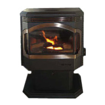
Featuring the
WARNING:
If the information in these instructions is not followed exactly, a fire or explosion
may result causing property damage, personal injury or loss of life.
-
Do not store or use gasoline or other flammable vapors and liquids in the vicinity of this or
any other appliance.
WHAT TO DO IF YOU SMELL GAS
• Do not try to light any appliance.
• Do not touch any electrical switch; do not use any phone in your building.
• Immediately call gas supplier from a neighbor's phone. Follow the gas supplier's instructions.
• If you cannot reach your gas supplier, call the fire department.
-
Installation and service must be performed by a qualified installer, service agency or the gas
supplier.
This appliance may be installed as an OEM installation in a manufactured (mobile) home and
must be installed in accordance with the manufacturer's instructions and the manufactured
home construction and safety standard, Title 24 CFR, Part 3280 or Standard for Installation in
Mobile Homes, CAN/CSA Z240 MH.
This appliance is only for use with the type(s) of gas indicated on the rating plate. A conversion
kit is supplied with the appliance.
Heritage Owner's Manual
Installer:
After installation give this manual to the home-owner
and explain operation of this heater.
Copyright 2004, T.I.
Burner
$10.00
100-01135
• Direct Vent Freestanding Stove
• Natural Gas or Propane
• Vent Horizontally or Vertically
• Standard Residential
• Mobile Home Approved
Tested and Listed by
Omni-Test Laboratories, Inc.
Beaverton, Oregon
Report # 028 – S – 19 - 1
4800 Harbour Pointe Blvd. SW
4040809
Mukilteo, WA 98275
ANSI Z21.88
Advertisement
Table of Contents

Related Manuals for Lopi heritage


Summary of Contents for Lopi heritage
- Page 1 Mobile Homes, CAN/CSA Z240 MH. This appliance is only for use with the type(s) of gas indicated on the rating plate. A conversion kit is supplied with the appliance. Heritage Owner’s Manual Installer: After installation give this manual to the home-owner and explain operation of this heater.
-
Page 2: Introduction
Introduction Introduction We welcome you as a new owner of a Heritage Stove. In purchasing this heater you have joined the growing ranks of concerned individuals whose selection of an energy system reflects both a concern for the environment and aesthetics. The Heritage is one of the finest home heaters the world over. -
Page 3: Table Of Contents
Table of Contents Introduction Operation Introduction ............2 Safety Notice ............20 Important Information .........2 Location of Controls ...........20 Safety Precautions Starting the Pilot Flame ........21 Starting the Heater for the First Time ......22 Safety Precautions ..........4 Turning the Heater On and Off ......22 Specifications Adjusting the Flame Height........22 Installation Options ..........6... -
Page 4: Safety Precautions
Safety Precautions • IF YOU SMELL GAS: Do not light any appliance Extinguish any open flame Do not touch any electrical switch or plug or unplug anything Open windows and vacate building Call gas supplier from neighbor’s house, if not reached, call fire department •... - Page 5 Safety Precautions • Do not place clothing or • Light the heater using the other flammable items on or built-in piezo igniter. Do not near the heater. Because use matches or any other this heater can be controlled external device to light your by a thermostat there is a heater.
-
Page 6: Specifications
Specifications Installation Options: Features: • Freestanding Stove • Ember Fyre ™ Burner for "Wood Fire" Look • Residential or Mobile Home • Works During Power Outages • Horizontal or Vertical Vent • Optional Thermostat or Remote Control • Variable-Rate Heat Output •... -
Page 7: Installation
Installation (for qualified installers only) Installation Warnings ! Failure to follow all of the requirements may result in property damage, bodily injury, or even death. ! This heater must be installed by a qualified installer who has gone through a training program for the installation of direct vent gas appliances. -
Page 8: Heater Placement Requirements
Installation (for qualified installers only) Heater Placement Requirements • Heater must be installed on a level surface capable of supporting the heater and vent • Due to the high temperature, the heater should be located out of traffic and away from furniture and draperies. -
Page 9: Vent Requirements
Installation (for qualified installers only) Vent Requirements Always maintain the required 1” clearance (air space) to combustible materials to prevent a fire hazard. Do not fill air spaces with insulation. The gas appliance and vent system must be vented directly to the outside of the building, and never be attached to a chimney serving a separate solid fuel or gas-burning appliance. -
Page 10: Approved Vent Configurations
Installation (for qualified installers only) Approved Vent Configurations Restrictor Position • A vent restrictor is built into the appliance to control the flow rate of exhaust gases. This ensures proper flames for the wide variety of vent configurations. Depending upon the vent configuration, you may be required to adjust the restrictor position. -
Page 11: Vertical Term's With (Or Without) 2 45° Elbows
Installation (for qualified installers only) Vertical Terminations with 0, 2, or 4 45° Offsets Offset Length Hor. Offset Vert. Rise Horizontal Offset None 5" Vertical 1' Section 1' 7" Rise 2' Section 1' 9" 2' 4" Offset Length 3' Section 2' 5"... - Page 12 Installation (for qualified installers only) Approved Venting Configurations with a Horizontal Termination • If using a Snorkel Termination (14” or 36”) add the snorkel height to the vertical height (snorkel terminations are used primarily for basement installations). • The termination must fall within the shaded area shown in the chart. Use restrictor position #1. Natural Gas (NG) Installations NOTE:...
-
Page 13: Vertical Term's With Two 90° Elbows
Installation (for qualified installers only) Vertical Terminations with Two or Three 90° Elbows • The termination must fall within the shaded area shown in the chart. Use the indicated restrictor position. 38' (max) 38' (max) 35 feet 35 feet Restrictor Position # 7 30 feet 30 feet... -
Page 14: Termination Requirements
Installation (for qualified installers only) Termination Requirements (see the illustration below) Minimum 9" clearance from any door or window Roof Minimum 12" above any grade, veranda, porch, deck or balcony Surface Minimum 12" from outside corner walls 11” Min. Minimum 12" from inside corner walls Roof 6”... -
Page 15: Finalizing The Installation
Installation (for qualified installers only) Finalizing the Installation Turn the gas control valve to “OFF” prior to conducting any service. Open the door (see page 17). Install the log set and coals (see page 18). We recommend you purge the gas line at this time (with the door open). This allows gas to be detected once it enters the firebox, ensuring gas does not build up. - Page 16 Installation (for qualified installers only) FINE TUNING THE EMBER-FYRE™ BURNER Each installation is affected by altitude, vent configuration, and fuel quality. Because of this, the restrictor and air shutter may need to be fine tuned to each installation. Follow the hints below to fine-tune the burner for optimum performance and aesthetics.
-
Page 17: Opening The Door
Installation (for qualified installers only) Opening the Door Swing the left panel back. Open both the top and bottom latch. Strike With the pawl free of the strike, the door may be swung open. Pawl Door Frame When securing the door, make sure the pawl fits over the strike before tightening. -
Page 18: Log Set And Coal Installation
Installation (for qualified installers only) Log Set and Coal Installation Step 1 Install the logs (see the illustration below). Place the rear log on the two platforms at the rear of the firebox. These pins insert into the holes in the log. - Page 19 Installation (for qualified installers only) Step 2 Install the twigs and ember chunk (see the illustration below). Place the left and right twigs as shown. Place the ember chunk as shown. Step 3 Install the embers along the front of the burner (see the illustrations below). Do not place the embers over the burner holes.
-
Page 20: Operation
Operation Safety Notice Read this entire manual (especially the “Safety Precautions” on pages 4 and 5) before using this stove. Failure to follow the instructions may result in property damage, bodily injury, or even death. Location of Controls The pilot flame is located ON/OFF Switch below the rear log. -
Page 21: Starting The Pilot Flame
Operation Starting The Pilot Flame The pilot flame is required to ignite the main burners (it also plays a safety role). It should be left on once lit. It will stay lit unless the gas control valve is turned to "OFF". However, the pilot will go out if the gas is shut off, the propane tank runs out (or low) or if the stove malfunctions. -
Page 22: Starting The Heater For The First Time
Operation Starting the Heater for the First Time Cleaning Gold Surfaces Fingerprints or other marks left on gold surfaces may become etched in place if they are not wiped clean prior to turning the stove on. With the heater cool, clean gold surfaces with denatured alcohol and a soft cloth. -
Page 23: Adjusting The Blower Speed
Operation Adjusting the Blower Speed The blower helps transfer heat from the heater into the room. It will not turn on until the heater is up to temperature (approximately 10 minutes after starting). See the illustration below for instructions on adjusting the blower speed. -
Page 24: Maintenance
Maintenance Cleaning Your Heater Warning: Fingerprints or other marks left on the optional gold surface may become etched in place if they are not wiped clean prior to turning the stove on. With the heater cool, use denatured alcohol and a soft cloth to clean gold surfaces. Other cleaners may leave a film that may become etched into the gold. -
Page 25: Troubleshooting Steps
Maintenance Troubleshooting Steps Problem: Possible Cause: Remedy: Pilot Will Not Flame A gas shut off valve is turned off ...... Check all gas shut off valves The gas control knob isn’t turned to “PILOT” ..See “Starting the Pilot Flame” Pg 21 The valve control knob isn’t pushed in .... -
Page 26: How This Heater Works
Maintenance How this Heater Works Warning This heater was designed with safety as the primary concern. Many of the components inside this heater are for safety purposes. Therefore, only certified gas service technicians should service this heater. What Turns the Main Burners On and Off This heater uses a millivolt system to control its operation (a millivolt is a very small amount of electricity). -
Page 27: Wiring Diagram
Maintenance Wiring Diagram Thermocouple Thermopile Piezo Igniter Millivolt Wiring On/Off Switch (for gas control valve) Brown Copper Co-Axial Wire Orange Spark Electrode White Pilot Hood 120 Volt Wiring Optional Remote Optional Control Thermostat Ground Black (green) White Power In Common Molex (white) Connector... -
Page 28: Safety Label
Safety Label The listing label is shown below for your records. It can be found inside the right side panel. Heritage DVL Stove Heritage Bay DVL FS) Listed Vented Report No. 028-S-14-1 Gas Fireplace Heater Tested and certified by OMNI-Test Laboratories, Inc. to the combustion performance and construction requirements of ANSI Z21.88/CSA 2.33-1998, applicable sections of UL 307b and CAN/CGA 2.17-M91. -
Page 29: Warranty
Warranty To register your TRAVIS INDUSTRIES, INC. 7 Year Warranty, complete the enclosed warranty card and mail it within ten (10) days of the appliance purchase date to: TRAVIS INDUSTRIES, INC., 4800 Harbour Pointe Blvd. SW, Mukilteo, WA 98275. TRAVIS INDUSTRIES, INC. warrants this gas appliance (appliance is defined as the equipment manufactured by Travis Industries, Inc.) to be defect-free in material and workmanship to the original purchaser from the date of purchase as follows: Check with your dealer in advance for any costs to you when arranging a warranty call. -
Page 30: Optional Equipment & Addenda
Optional Equipment LP Conversion Instructions Install the conversion kit prior to installing the gas line to ensure proper gas use. Open the door (see page 17). Remove the logs and coals (if installed - page 18) Remove the burner (see illustration below). Lift the pilot hood off the pilot assembly (you may need to pull Remove the cast floor. - Page 31 Optional Equipment Follow the directions below to replace the orifices. Slide the air shutters all the way to the left. Rear Orifice Front Orifice Manifold Use a 1/2” open end wrench Apply thread sealant to the LP to unscrew both orifices. orifices prior to installation.
- Page 32 Optional Equipment Remove the pilot orifice following the instructions below. Replace with the propane pilot orifice Remove the orifice and replace with the LP orifice. Screw the Lift the pilot hood off the pilot orifice all the way in and replace the pilot hood. assembly.
-
Page 33: Fireback
Optional Equipment Make the gas line connection, bleed the gas line (if applicable), start the heater and thoroughly leak- test all gas connections and the gas control valve. Check the pilot. Adjust if necessary. WARNING: When lighting or re-lighting the pilot, the door must be opened (see page 17). -
Page 34: Gold Door
Optional Equipment Gold Door (part # 99300212) Follow the directions below to install the optional gold door. WARNING: Clean the gold surface prior to Remove the black door by starting the stove. Any marks sliding it up and off the door left on the gold may become frame. -
Page 35: Installation Addenda
Installation Addenda ADDENDUM #1 Class A Chimney Screw the Retro Retro Vertical Top Conversion Kit Vertical Top to the (screw to chimney) Flex Pipe Simpson Duravent provides a conversion kit for those wishing to use an existing wood stove chimney to vent this direct vent stove. The illustration below gives an overview of this type of installation. -
Page 36: Index
Index Adjusting the Blower Speed......23 Lifting Flames..........16 Adjusting the Flame Height ......22 Listing Label (Safety Label) ......28 AFUE............6 Log Installation ...........18 Air Shutter Adjustment........15 Maintaining Your Stove’s Appearance..24 Alcoves (see “Heater Placement Req.”) ..8 Natural Gas Verses Propane......4 Altitude Considerations.......9 On/Off Operation........22 Amperage (of blower)........6 On/Off Switch (Location)......20...