Table of Contents
Advertisement
WARNING: FIRE OR EXPLOSION HAZARD
Failure to follow safety warnings exactly could result in serious injury, death, or property damage.
- Do not store or use gasoline or other flammable vapors and liquids in the vicinity of this or any
other appliance.
- WHAT TO DO IF YOU SMELL GAS
• Do not try to light any appliance.
• Do not touch any electrical switch; do not use any phone in your building.
• Leave the building immediately
• Immediately call your gas supplier from a neighbor's phone. Follow the gas supplier's
instructions.
• If you cannot reach your gas supplier, call the fire department.
-
Installation and service must be performed by a qualified installer, service agency or the gas supplier.
A barrier designed to reduce the risk of burns from
the hot viewing glass is provided with this appliance
and shall be installed for the protection of children
and other at-risk individuals.
This appliance may be installed in an aftermarket, permanently located, manufactured home
(USA only) or mobile home, where not prohibited by local codes.
This appliance is only for use with the type of gas indicated on the rating plate. A conversion
kit is supplied with the appliance.
INSTALLER: Leave this manual with the appliance.
CONSUMER: Retain this manual for future reference.
Travis Industries, Inc.
Copyright 2016, T.I.
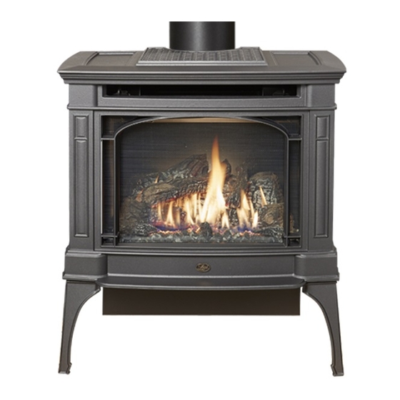
Berkshire GSR2
Deluxe (3-Sided)
Owner's Manual
HOT GLASS WILL CAUSE
BURNS
DO NOT TOUCH GLASS
UNTIL COOLED
NEVER ALLOW CHILDREN
TO TOUCH GLASS
12521 Harbour Reach Dr., Mukilteo, WA 98275
$10.00
Direct Vent Stove
Natural Gas or Propane
Residential or Mobile
French language manuals at travisindustries.com
Manuels de langue Française à travisindustries.com
12/27/2018
Tested and Listed by
ANSI Z21.88-2014
CSA 2.33-2014
Home
www.travisproducts.com
100-01440
Advertisement
Table of Contents

Related Manuals for Lopi Berkshire GSR2 Deluxe


Summary of Contents for Lopi Berkshire GSR2 Deluxe
- Page 1 Berkshire GSR2 Deluxe (3-Sided) Owner’s Manual WARNING: FIRE OR EXPLOSION HAZARD Failure to follow safety warnings exactly could result in serious injury, death, or property damage. - Do not store or use gasoline or other flammable vapors and liquids in the vicinity of this or any other appliance.
-
Page 2: Introduction
Introduction Introduction We welcome you as a new owner of a Lopi Berkshire GSR2 stove. In purchasing a Berkshire you have joined the growing ranks of concerned individuals whose selection of an energy system reflects both a concern for the environment and aesthetics. The Berkshire is one of the finest home heaters the world over. -
Page 3: Table Of Contents
Table of Contents Introduction ..............2 Rockwool Installation ............ 32 Before You Begin ............. 33 Important Information ..........2 Remote Set-Up ............34 Listing Details ............. 2 Verify the Switch is on “REMOTE” ........ 34 ... - Page 4 Safety Precautions Failure to follow all of the requirements may result in property damage, bodily injury, or even death. Young children should be carefully supervised when they are in the same room as the appliance. Toddlers, young children and others may be susceptible to accidental contact burns.
- Page 5 Safety Precautions Safety Warnings (continued) Because this heater can be controlled by a thermostat there is a possibility of the heater turning on and igniting any items placed on or near the appliance. Light the heater using the built-in igniter. Do not use matches or any other external device to light your heater.
-
Page 6: Features
Specifications Features: Installation Options: Ember Fyre™ Burner for "Wood Fire" Look Freestanding Stove Works During Power Outages (battery backup system) Horizontal or Vertical Vent High Efficiency Residential or Mobile Home Remote Control with Thermostat Includes High-Tech Blower for Quick Heat Distribution Straight or Corner Placement Variable Heat Output Bedroom Approved... -
Page 7: Packing List
Installation (for qualified installers only) Installation Warnings Failure to follow all of the requirements may result in property damage, bodily injury, or even death. This heater must be installed by a qualified installer who has gone through a training program for the installation of direct vent gas appliances. -
Page 8: Stove Clearances
Installation (for qualified installers only) Installation Hints If converting to LP, convert the appliance prior to installation. Install the logs last - they are fragile. When determining the location of the stove, locate the wall studs (for horizontal penetrations) and ceiling trusses (for vertical penetrations). -
Page 9: Heater Placement Requirements
Installation (for qualified installers only) Heater Placement Requirements • Heater must be installed on a level surface capable of supporting the heater and vent. • Due to the high temperature, the heater should be located out of traffic and away from furniture and draperies. -
Page 10: Gas Line Installation
Installation (for qualified installers only) Gas Line Installation DO NOT CONNECT THIS UNIT TO A CHIMNEY FLUE SERVING ANOTHER APPLIANCE. • The gas line must be installed in accordance with all local codes and the requirements listed below. In the absence of local codes, follow ANSI 223.1 in US/Canada or AS/NZS 5601.1 in Australia. -
Page 11: Vent Requirements
Installation (for qualified installers only) Vent Requirements • The gas appliance and vent system must be vented directly to the outside of the building, and never be attached to a chimney serving a separate solid fuel or gas-burning appliance. Each direct vent gas appliance must use its own separate vent system. -
Page 12: Approved Vent
Installation (for qualified installers only) Approved Vent Use 6-5/8" (168mm) diameter Simpson Dura-Vent Direct-Vent Pro (or GS)*. * Other vent may be approved with this stove. Check with the vent manufacturer for details. Always use the high-wind cap (or high-wind sconce cap, part # 46DVA-HSCH). ... -
Page 13: Approved Vent Configurations
Installation (for qualified installers only) Approved Vent Configurations Restrictor Position • A restrictor is built into the appliance to control the flow rate of exhaust gases. This ensures proper flames for the wide variety of vent configurations. Depending upon the vent configuration, you may be required to adjust the restrictor position. -
Page 14: Vertical Terminations With Two 45° Elbows
Installation (for qualified installers only) Vertical Terminations with Two 45° Elbows • 10’ (3.1M) Minimum System Height (with or without offsets) • 40’ (12.2M) Maximum System Height 40' max (12m) 40' max (12m) Restrictor • 24’ (7.3M) Maximum Offset Position # 6 •... -
Page 15: Horizontal Termination With One 90° Elbow
Installation (for qualified installers only) Horizontal Termination with One 90° Elbow YOU MUST PUT A MINIMUM 2’ VERTICAL SECTION (3’ FOR LP) ON TOP OF THE STOVE BEFORE ELBOW • If using a Snorkel Termination (14” (356mm) or 36” (915mm)) add the snorkel height to the vertical height (snorkel terminations are used primarily for basement installations). -
Page 16: Horizontal Termination With Two Elbows
Installation (for qualified installers only) Horizontal Termination with Two Elbows YOU MUST PUT A MINIMUM 2’ VERTICAL SECTION (3’ FOR LP) ON TOP OF THE STOVE BEFORE ELBOW • Includes one 90° vertical elbow and one 90° or 45° horizontal elbow •... -
Page 17: Horizontal Termination With Three 90° Elbows (All Vertical)
Installation (for qualified installers only) Horizontal Termination with Three 90° Elbows (all vertical) • If using a Snorkel Termination (14” (356mm) or 36” (915mm)) add the snorkel height to the vertical height (snorkel terminations are used primarily for basement installations). •... -
Page 18: Vertical Terminations With Two 90° Elbows
Installation (for qualified installers only) Vertical Terminations with Two 90° Elbows • The termination must fall within the shaded area shown in the chart. Use the indicated restrictor position. 40' max (12m) 40' max (12m) Restrictor Position # 6 35 feet (10.5m) 35 feet (10.5m) Restrictor Position # 5... -
Page 19: Vertical Terminations With Three 90° Elbows
Installation (for qualified installers only) Vertical Terminations with Three 90° Elbows • Includes two 90° vertical elbows and one 90° or 45° horizontal elbow • The termination must fall within the shaded area shown in the chart. Use the indicated restrictor position. -
Page 20: Vent Termination Requirements (See Illustration Below)
Installation (for qualified installers only) Vent Termination Requirements (see illustration below) Venting terminals shall not be recessed into a wall or siding. Minimum 9" (229mm) clearance from any door or window Roof Minimum 12" (305mm) above any grade, veranda, porch, deck or balcony Surface Minimum 1"... -
Page 21: Class A Chimney Conversion Kit
Installation (for qualified installers only) Class A Chimney Conversion Kit Duravent provides a conversion kit for those wishing to use an existing wood stove chimney to vent this direct vent stove. The illustration below gives an overview of this type of installation. See the instructions included with the kit for details. -
Page 22: Interior Masonry Chimney Conversions
Installation (for qualified installers only) Interior Masonry Chimney Conversions • Follow the requirements and use the equipment listed in the illustration below to install this appliance into an interior masonry chimney. • Maximum vertical rise is 40' (12M) • Minimum vertical rise is 10' (3M) •... -
Page 23: Steps For Finalizing The Installation
Installation (for qualified installers only) Steps for Finalizing the Installation 1. Remove the glass (see page 25). NOTE: If using propane (LP) convert the appliance prior to installing the logs. 2. We recommend you purge the gas line at this time (with the glass removed). This allows gas to be detected once it enters the firebox, ensuring gas does not build up. -
Page 24: Air Shutter Adjustment
Installation (for qualified installers only) 5. Install the logs (see page 27). 6. Replace the glass. 7. Start the heater. 8. Leak test all gas joints. 9. Check the air shutter following the directions below. Air Shutter Adjustment Let the heater burn for fifteen minutes (make sure the logs and glass are in place). The flames should be yellow with no sooting. -
Page 25: Face And Glass Removal
Finalizing the Installation (for qualified installers only) Face and Glass Removal A barrier designed to reduce the risk of burns from the hot viewing glass is provided with this appliance and shall be installed for the protection of children and other at-risk individuals. If the barrier becomes damaged, the barrier shall be replaced with the manufacturer’s barrier for this appliance. - Page 26 Finalizing the Installation (for qualified installers only) Glass Frame Removal and Installation (continued) The latch can come loose from glass frame anchor. This occurs when it is turned 1/4 turn when it is disengaged. Follow the directions below to re-install the latch if it becomes loose. Hold the latch at an angle and insert it into the slot on the glass frame anchor.
-
Page 27: Log Installation
Finalizing the Installation (for qualified installers only) Log Installation The logs are fragile, especially after being exposed to heat. Make sure the gas control valve is “OFF” and the heater is cool prior to conducting service. Failure to position the parts in accordance with these diagrams or failure to use only parts specifically approved with this appliance may result in property damage or personal injury. -
Page 28: Left Front Log Placement
Finalizing the Installation (for qualified installers only) Left Front Log Placement The left front log has two holes on the bottom. Place the log so the pin on the burner and the metal bracket insert into the holes on the log (see photos below). NOTE: On LP push the log to the back. -
Page 29: Right Front Log Placement
Finalizing the Installation (for qualified installers only) Right Front Log Placement The right log has two holes on the bottom. Place the log so both burner pins insert into the holes on the log (see photos below). Make sure the log is pushed back so it sits flat. NOTE: On LP push the log to the back. -
Page 30: Right Cross Log Placement
Finalizing the Installation (for qualified installers only) Right Cross Log Placement Place the log as shown below. The right cross log rests on the flat spots of the rear and the right front logs. Left Twig Placement Place the left twig on the burner as shown below. Make sure it does not cover any burner holes. ©... -
Page 31: Center Twig Placement
Finalizing the Installation (for qualified installers only) Center Twig Placement Place the center twig on the burner as shown below. Make sure it does not cover any burner holes. The completed installation is shown below. © Travis Industries 12/27/2018 - 1440 Berkshire GSR2 3-Sided... -
Page 32: Ember Placement
Finalizing the Installation (for qualified installers only) Ember Placement Place a layer of embers along any screw heads and visible edges of the burner. Rockwool Installation The included rock wool is placed on top of the burner to enhance the glow from the burner. The rock wool works best when it is applied in a very thin, porous layer. -
Page 33: Before You Begin
Operation Before You Begin Read this entire manual before you use your new heater (especially the section "Safety Precautions" on pages 4 & 5). Failure to follow the instructions may result in property damage, bodily injury, or even death. Remote Control Warnings KEEP BATTERIES AND COVER INSTALLED AT ALL TIMES... -
Page 34: Remote Set-Up
Operation Remote Set-Up Verify the Switch is on “REMOTE” The battery holder has a switch built into it (see illustration below). This switch must remain in the REMOTE position for the remote to operate. Synchronize the Transmitter to the IFC The transmitter will need to be synchronized to the IFC (Integrated Fireplace Control) before the remote will work correctly. -
Page 35: Location Of Controls
Operation Location of Controls Most features will be controlled by the included remote. The battery holder / switch is on the right side, below the firebox. Direct Operation The fireplace may be directly operated from the battery holder. The three positions are below (see illustration below): ON –... -
Page 36: Starting The Stove For The First Time
Operation Starting the Stove for the First Time Burn the heater at a high setting with the blower off for an extended period (up to 48 hours). This will cure the painted surfaces. Fumes from the paint curing and oil burning off the steel will occur. This is normal. -
Page 37: Remote Operation
Operation Remote Operation When the switch on the battery holder is set to “REMOTE” the transmitter operates the fireplace. Once you understand how the transmitter works, you will be able to operate your fireplace quickly and easily. Display Overview The transmitter display has four main sections (see illustration below). Thermostat Display Room Temperature Display Read-Out (Thermostat Setting, Function, etc.) -
Page 38: Manual On-Off / Smart Thermostat / Standard Thermostat
Operation Manual On-Off / Smart Thermostat / Standard Thermostat Use the thermostat button to cycle through the three thermostat settings (see illustration below). Look here for the Press the thermostat button to cycle thermostat setting. through the thermostat settings. SMART ... -
Page 39: Mode Controls (Flame, Blower, Light, Comfort Control)
Operation Mode Controls (Flame, Blower, Light, Comfort Control) Use the mode button to cycle through the four mode controls (see illustration below). Press the mode button to cycle through the mode settings. Flame Comfort Height Control Look here for mode controls. Accent Optional Light... -
Page 40: Mode Controls - Continued
Operation Mode Controls - continued Accent Light The Accent Light (night light) inside the heater may be turned on and off using the up and down buttons when in Accent Light Mode (see illustration below). The center display will display the 7 settings, from “OFF”... -
Page 41: Low Battery Indicator
Operation Low Battery Indicator Transmitter Batteries The transmitter has a battery-level indicator. When it indicates low battery voltage (see illustration below), install three new AAA alkaline batteries into the transmitter (see “Transmitter Battery Installation” on page 41). Low Battery Indicator IFC Batteries The IFC (Integrated Fireplace Control) will “beep”... -
Page 42: Child-Proof Feature
Operation Child-Proof Feature The child proof feature disables the control buttons, preventing un-wanted use of the remote. Press both the MODE and UP buttons simultaneously to turn this feature on and off (see illustration below). HINT: This feature is especially useful while using the thermostat setting. Child Proof Indicator Normal Operating Sounds Extinction Pops... -
Page 43: Maintaining Your Stove's Appearance
Maintenance (for qualified service personnel only) DANGER HIGH VOLTAGE: Disconnect power before attempting maintenance or repair. Maintaining Your Stove's Appearance Painted Surfaces • Painted surfaces should be cleaned with a duster. If scratches occur, lightly sand the area with fine sandpaper. -
Page 44: Yearly Service Procedure
Maintenance (for qualified service personnel only) Yearly Service Procedure WARNING: Failure to inspect and maintain the stove may lead to improper combustion and a potentially dangerous situation. We recommend the following procedures be done by a qualified technician. Shut off gas to the fireplace and let it cool for 15 minutes. Remove the glass. Inspect and operate the pressure relief mechanism to verify relief mechanisms are free from obstruction to operate. -
Page 45: Troubleshooting Table
Maintenance (for qualified service personnel only) Troubleshooting Table Don't Call for Service Until Problem: Possible Cause: You: The battery box switch is turned to "OFF" Turn the battery box switch to "ON". The remote control is not working correctly See the remote control instructions. Burner Will Not Start The thermostat is disconnected or set too low See "Thermostat Operation". -
Page 46: Wiring Diagram
Maintenance (for qualified service personnel only) Wiring Diagram Caution: Label all wires prior to disconnection when servicing controls. Wiring errors can cause improper and dangerous operation. Accessory Power Black White Black White Accent Light (s) Optional Blower(s) Power 3 Amp Fuse 3 Amp Fuse Appliance Ground... -
Page 47: Safety Label
Safety Label Safety Label The safety (listing) label is on the back of the stove. A copy is shown below. © Travis Industries 12/27/2018 - 1440 Berkshire GSR2 3-Sided... -
Page 48: Conditions & Exclusions
Limited 7 Year Warranty Register your TRAVIS INDUSTRIES, INC. Limited 7 Year Warranty online at traviswarranty.com. TRAVIS INDUSTRIES, INC. warrants this gas appliance (appliance is defined as the equipment manufactured by Travis Industries, Inc.) to be defect-free in material and workmanship to the original purchaser from the date of purchase as follows: Check with your dealer in advance for any costs to you when arranging a warranty call. -
Page 49: Lp Conversion Instructions
Optional Equipment (for qualified installers only) LP Conversion Instructions Install the conversion kit prior to installing the gas line to ensure proper gas use. The GSR Stepper Motor Kit is required for converting this appliance to LP (4-pack = 94400999, single = 250-01463). The kit contains the stepper motor (regulator) and torx wrench. - Page 50 Optional Equipment (for qualified installers only) Remove the manifold cover to access the burner orifices (see below). Replace the manifold cover after the LP burner orifices are installed. Follow the directions below to replace the orifices. Rear Burner Orifice Front Burner Orifice Thread Sealant 15/16"...
- Page 51 Optional Equipment (for qualified installers only) Remove and discard the NG air deflector. Attach the LP air deflector included with the stove. Note how the LP deflector has a notch along the bottom. NG Air Deflector LP Air Deflector Install the LP pilot orifice following the directions below. (a) Use a 7/16”...
- Page 52 Optional Equipment (for qualified installers only) Remove the control panel to access the gas control valve. The stepper motor (adjustable regulator) has an installation sheet included with it – make sure to follow all of the directions. Place the stepper motor on the gas control valve (see pictures below) –...
- Page 53 Optional Equipment (for qualified installers only) © Travis Industries 12/27/2018 - 1440 Berkshire GSR2 3-Sided...
-
Page 54: Index
Index Index Accent Light Replacement ....... 43 Introduction ............2 Additional Items Required ........7 Listing Details ............. 2 Approved Vent Configurations ......13 Location of Controls ......... 35 Battery Replacement ........41 Log Installation ..........27 Before You Begin ..........33 Low Battery Indicator ........