Table of Contents
Advertisement
Quick Links
Advertisement
Table of Contents

Related Manuals for Supero SC510T-200B


Summary of Contents for Supero SC510T-200B
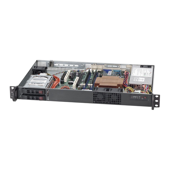
- Page 1 UPER ® SC510T Chassis Series SC510T-200B USER’S MANUAL...
- Page 2 SC510T-200B Chassis Manual The information in this User’s Manual has been carefully reviewed and is believed to be accurate. The vendor assumes no responsibility for any inaccuracies that may be contained in this document, makes no commitment to update or to keep current the information in this manual, or to notify any person or organization of the updates.
- Page 3 SC510T chassis. Installation and maintenance should be performed by experienced technicians only. Supermicro’s SC510T-200B chassis features a unique and highly-optimized design for dual-core Intel Xeon 300/Core 2 Duo platforms. The chassis is equipped with a 200W high efficiency power supply for superb power savings.
-
Page 4: Manual Organization
SC510T Chassis Manual Manual Organization Chapter 1 Introduction The first chapter provides a checklist of the main components included with this SC510T-200B chassis and describes the main features of the chassis. This chap- ter also includes contact information. Chapter 2 System Safety This chapter lists warnings, precautions, and system safety. -
Page 5: Table Of Contents
Preface Table of Contents Chapter 1 Introduction Overview ......................1-1 Shipping List ....................1-1 Part Numbers ....................1-1 Where to get Replacement Components ............1-2 Contacting SuperMicro ..................1-3 Returning Merchandise for Service..............1-4 Chapter 2 System Safety Overview ......................2-1 Warnings and Precautions ................ - Page 6 Replacing the Power Supply ................. 4-13 Chapter 5 Rack Installation Overview ......................5-1 Unpacking the System ..................5-1 Preparing for Setup ..................5-1 Choosing a Setup Location ................5-1 Rack Precautions .................... 5-2 General Server Precautions ................5-2 Rack Mounting Considerations ............... 5-3 Ambient Operating Temperature ..............
-
Page 7: Chapter 1 Introduction
Chapter 1: Introduction Chapter 1 Introduction Overview Supermicro’s SC510T-200B chassis features a unique and highly-optimized design. The chassis is equipped with high efficiency 80%+ low noise power supply. Shipping List Part Numbers Please visit the following link for the latest shiping lists and part numbers for your particular chassis model http://www.supermicro.com/... -
Page 8: Where To Get Replacement Components
SC510 Chassis Manual Where to get Replacement Components Though not frequently, you may need replacement parts for your system. To en- sure the highest level of professional service and technical support, we strongly recommend purchasing exclusively from our Supermicro Authorized Distributors / System Integrators / Resellers. -
Page 9: Contacting Supermicro
Chapter 1: Introduction Contacting Supermicro Headquarters Address: Super Micro Computer, Inc. 980 Rock Ave. San Jose, CA 95131 U.S.A. Tel: +1 (408) 503-8000 Fax: +1 (408) 503-8008 Email: marketing@supermicro.com (General Information) support@supermicro.com (Technical Support) www.supermicro.com Site: Europe Address: Super Micro Computer B.V. Het Sterrenbeeld 28, 5215 ML 's-Hertogenbosch, The Netherlands Tel:... -
Page 10: Returning Merchandise For Service
SC510 Chassis Manual Returning Merchandise for Service A receipt or copy of your invoice marked with the date of purchase is required be- fore any warranty service will be rendered. You can obtain service by calling your vendor for a Returned Merchandise Authorization (RMA) number. When returning to the manufacturer, the RMA number should be prominently displayed on the outside of the shipping carton, and mailed prepaid or hand-carried. -
Page 11: Chapter 2 System Safety
Chapter 2: System Safety Chapter 2 System Safety Overview This chapter provides a quick setup checklist to get your chassis up and running. Following the steps in order given should enable you to have your chassis setup and operational within a minimal amount of time. This quick set up assumes that you are an experienced technician, famailiar with common concepts and terminology. -
Page 12: Electrical Safety Precautions
SC510 Chassis Manual Electrical Safety Precautions Basic electrical safety precautions should be followed to protect yourself from harm and the SC510T-200B from damage: • Be aware of the locations of the power on/off switch on the chassis as well as the room’s emergency power-off switch, disconnection switch or electrical outlet. -
Page 13: General Safety Precautions
Chapter 2: System Safety • DVD-ROM laser: CAUTION - This server may have come equipped with a DVD-ROM drive. To prevent direct exposure to the laser beam and hazardous radiation exposure, do not open the enclosure or use the unit in any uncon- ventional way. - Page 14 SC510 Chassis Manual • Touch a grounded metal object before removing any board from its antistatic bag. • Do not let components or PCBs come into contact with your clothing, which may retain a charge even if you are wearing a wrist strap. •...
-
Page 15: Chapter 3 Chassis Components
Chapter 3: Chassis Components Chapter 3 Chassis Components Overview This chapter describes the most common components included with your chassis. Some components listed may not be included or compatible with your particular chassis model. For more information, see the installation instructions detailed later in this manual. -
Page 16: Mounting To A Rack (Optional)
SC510 Chassis Manual Mounting to a Rack (optional) The SC510T can be placed in a rack for secure storage and use. To setup your rack, follow the step-by-step instructions included in this manual. Power Supply Each SC510T chassis model includes a high-efficiency 80%+ low noise power sup- ply with thermal control fan, rated at 200 Watts. -
Page 17: Chapter 4 Chassis Setup And Maintenance
Chapter 4: Chassis Setup and Maintenance Chapter 4 Chassis Setup and Maintenance Overview This chapter covers the procedures required to install components and perform maintenance on the chassis. The only tool you will need to install components and perform maintenance is a Phillips screwdriver. Review the warnings and precautions listed in the manual be- fore setting up or servicing this chassis. -
Page 18: Removing The Chassis Cover
SC510 Chassis Manual Removing the Chassis Cover Figure 4-1: Removing the Chassis Cover Removing the Cover Remove the six screws that hold the chassis cover in place.There are two screws on each side of the chassis, one screw on the front and one screw on the back. -
Page 19: Removing And Installing The Hard Drives
Chapter 4: Chassis Setup and Maintenance Removing and Installing the Hard Drives The SC510T supports two 2.5" hot-swappable hard drives, which can be removed without powering-down the system. Removing and Installing Hard Drives Push the release button on the front of the hard drive carrier. The handle of the hard drive carrier will extend. -
Page 20: Installing The Motherboard
SC510 Chassis Manual Installing the Motherboard Figure 4-4: Installing the Motherboard Permanent and Optional Standoffs Standoffs prevent short circuits by securing space between the motherboard and the chassis surface. The SC510T chassis includes permanent and removable standoffs on the chassis floor. These standoffs accept the rounded Phillips head screws included in the SC510T accessories packaging. -
Page 21: Installing The Motherboard:
Chapter 4: Chassis Setup and Maintenance Installing the Motherboard Motherboard Installation Review the documentation that came with your motherboard. Become familiar with component placement, requirements, precautions, and cable connec- tions. Open the chassis cover. Remove any standoffs which must be taken out in order to fit the mother- board (see previous page). -
Page 22: Add-On Card/Expansion Slot Setup
SC510 Chassis Manual Add-on Card/Expansion Slot Setup SC510T chassis includes an I/O slot for an optional add-on card. A low-profile, half- length PCI add-on card is supported. A riser card is required in order to adapt the add-on card to the 1U chassis. For further information on add-on cards and risers cards, refer to the Supermicro Website at www.supermicro.com Add-on Card Clip Figure 4-5: Locating the Add-on Card Clip... - Page 23 Chapter 4: Chassis Setup and Maintenance Insert the assembled add-on card and riser card into the expansion slot inside the chassis, carefully aligning the plate of the add-on card with the openings in the back of the chassis. Replace the add-on card clip and screw it onto the chassis to hold the add-on card in place.
-
Page 24: Replacing The Heatsink
SC510 Chassis Manual Replacing the Heatsink The SC510T chassis requires a heatsink, which conducts heat away from the motherboard. Replacing the Heatsink Unplug all power leading to the chassis. Remove the 4 mounting screws which attach the heatsink to the motherboard and set them aside for later use. -
Page 25: Installing The Air Shroud
Chapter 4: Chassis Setup and Maintenance Installing the Air Shroud Figure 4-9: Installing the Air Shroud Air shrouds concentrate airflow to maximize fan efficiency. The SC510T chassis air shroud does not require screws to set up. Use the air shroud included with your chassis, unless an active heatsink is being used. -
Page 26: Checking The Server's Air Flow
SC510 Chassis Manual Checking the Server's Air Flow Checking the Air Flow Make sure there are no objects to obstruct airflow in and out of the server. Use only recommended server parts. Make sure no wires or foreign objects obstruct air flow through the chassis. Pull all excess cabling out of the airflow path, or use shorter cables. -
Page 27: Replacing System Fans
Chapter 4: Chassis Setup and Maintenance Replacing System Fans The SC510T chassis comes equipped with three system fans for optimal cooling. There is a single fan located behind the hard disk drives, and set of two fans located in front of the motherboard. These fans circulate air through the chassis as a means of lowering the chassis internal temperature. - Page 28 SC510 Chassis Manual Figure 4-12: Removing the Fan Housings from the Chassis To remove the fans from the fan housing, gently push upwards on the fan from the underside of the fan housing. Gently ease the fan out of the top of the fan housing Figure 4-13: Removing Fans from Fan Housings Slide the replacement fan...
-
Page 29: Power Supply
Chapter 4: Chassis Setup and Maintenance Power Supply The SC510T chassis has one 200 Watt power supply. This power supply is auto- switching capable. This enables it to automatically sense and operate at a 100v to 240v input voltage. In the unlikely event that the power supply unit fails, the system will shut down and you will need to change the power supply unit. - Page 30 SC510 Chassis Manual Remove the power supply from the chassis. Align the mounting thru holes on the power supply with the mounting holes in the chassis and reattach the power supply to the chassis using the four screws which were previously set aside Connect the chassis wiring to the power supply.
-
Page 31: Chapter 5 Rack Installation
Chapter 5: Rack Installation Chapter 5 Rack Installation Overview This chapter provides a quick setup checklist to get your chassis up and running. Following these steps in the order given should enable you to have the system operational in a minimal amount of time. Unpacking the System You should inspect the box the chassis was shipped in, and note if it was damaged in any way. -
Page 32: Rack Precautions
SC510 Chassis Manual • This product is for installation only in a Restricted Access Location (dedicated equipment rooms, service closets and similar environments). Warnings and Precautions! Rack Precautions • Ensure that the leveling jacks on the bottom of the rack are fully extended to the floor with the full weight of the rack resting on them. -
Page 33: Rack Mounting Considerations
Chapter 5: Rack Installation Rack Mounting Considerations Ambient Operating Temperature If installed in a closed or multi-unit rack assembly, the ambient operating tempera- ture of the rack environment may be greater than the ambient temperature of the room. Therefore, consideration should be given to installing the equipment in an environment compatible with the manufacturer’s maximum rated ambient tempera- ture (TMRA). -
Page 34: Rack Mounting Instructions
SC510 Chassis Manual Rack Mounting Instructions This section provides information on installing the SC510T chassis into a rack unit There are a variety of rack units on the market, which may mean the assembly procedure will differ slightly. You should also refer to the installation instructions that came with the rack unit you are using. -
Page 35: Appendix A Cables, Screws, And Other Accessories
This appendix lists supported cables for your chassis system. It only includes the most commonly used components and configurations. For more compatible cables, refer to the manufacturer of the motherboard you are using and our Web site at: www.supermicro.com. A-2 Cables Included with SC510T Chassis SC510T-200B Part # Type Length Description... -
Page 36: Extending Power Cables
SC510 Chassis Manual Extending Power Cables Although Supermicro chassis are designed with to be efficient and cost-effective, some compatible motherboards have power connectors located in different areas. To use these motherboards you may have to extend the power cables to the mother boards. - Page 37 Appendix A: Chassis Cables A-3 Chassis Screws The accessory box includes all the screws needed to setup your chassis. This section lists and describes the most common screws used. Your chassis may not require all the parts listed. HARD DRIVE Flat head Pan head 6-32 x 5 mm...
- Page 38 SC510 Chassis Manual Notes...
-
Page 39: Appendix B Sc510T Power Supply Specifications
Appendix B: Power Supply Specifications Appendix B SC510T Power Supply Specifications This appendix lists power supply specifications for your chassis system. SC510T-200B 200W MFR Part # PWS-201-1H 100 - 240V Rated AC Voltage 50 - 60Hz 4-2Amp +5V standby 2 Amp... - Page 40 SC510 Chassis Manual Notes...
-
Page 41: Appendix C Sas-510T Backplane Specifications
Appendix C: Backplane Specifications Appendix C SAS-510T Backplane Specifications To avoid personal injury and property damage, carefully follow all the safety steps listed below when accessing your system or handling the components. C-1 ESD Safety Guidelines Electrostatic Discharge (ESD) can damage electronic com ponents. To prevent dam- age to your system, it is important to handle it very carefully. - Page 42 SC510T Chassis Manual C-3 An Important Note to Users • All images and layouts shown in this user's guide are based upon the latest PCB Revision available at the time of publishing. The card you have received may or may not look exactly the same as the graphics shown in this manual.
- Page 43 Appendix C: Backplane Specifications Jumper Settings and Pin Definitions C-4 Front Components C285 JP10 JP25 REV 1.01 SAS510T JP25:OH TEMP OPEN:45 2-3:55 1-2:50 DESIGNED IN USA Figure C-1: Front Components The SAS-510T backplanes features the following front components: Front Connectors Power Connector: (4-pin) JP10 SATA Connector: (7-pin), J5, connect to cable.
- Page 44 SC510T Chassis Manual C-5 Front Connector and Pin Definitions 1. Power Connector Backplane Main Power The 4-pin connector designated JP10 provides 4-Pin Connector (JP10) power to the backplane. See the table on the Pin# Definition right for pin definitions. +12V 2 and 3 Ground 2.
-
Page 45: Explanation Of Jumpers
Appendix C: Backplane Specifications C-6 Front Jumper Locations and Pin Definitions C285 JP10 JP25 JP25 REV 1.01 SAS510T JP18 JP25:OH TEMP OPEN:45 2-3:55 1-2:50 DESIGNED IN USA Figure C-2: Front Jumpers Explanation of Jumpers To modify the operation of the backplane, Connector Pins jumpers can be used to choose between... - Page 46 SC510T Chassis Manual C-7 Front LED Indicators JP25 REV 1.01 SAS510T C285 JP10 JP25 REV 1.01 SAS510T JP25:OH TEMP OPEN:45 2-3:55 1-2:50 DESIGNED IN USA Figure C-3: Front LEDs Front LEDs 2-3:55 STATE SPECIFICATION Overheat/drive failure LED indicator (Red light: flashing, buzzer: on)
- Page 47 Appendix C: Backplane Specifications C-8 Rear Connectors and LED Indicators ACT#1 SAS#1 FAIL#1 SAS #1 ACT#0 SAS #0 SAS#0 FAIL#0 Figure C-4: Rear Components Rear SAS/SATA Connectors Rear Connector SAS Drive Connector Number Number SAS #0 SAS/SATA HDD #0 SAS #1 SAS/SATA HDD #1 Rear LED Indicators Rear...
- Page 48 SC510T Chassis Manual Disclaimer (cont.) The products sold by Supermicro are not intended for and will not be used in life sup- port systems, medical equipment, nuclear facilities or systems, aircraft, aircraft devices, aircraft/emergency communication devices or other critical systems whose failure to per- form be reasonably expected to result in significant injury or loss of life or catastrophic property damage.