Table of Contents
Advertisement
Quick Links
Advertisement
Table of Contents

Related Manuals for Supero SC523L-410B


Summary of Contents for Supero SC523L-410B
- Page 1 UPER ® SC523 Chassis Series SC523L-520B SC523L-410B USER’S MANUAL...
- Page 2 Please Note: For the most up-to-date version of this manual, please see our web site at www.supermicro.com. Super Micro Computer, Inc. ("Supermicro") reserves the right to make changes to the product described in this manual at any time and without notice. This product, including software, if any, and documentation may not, in whole or in part, be copied, photocopied, reproduced, translated or reduced to any medium or machine without prior written consent.
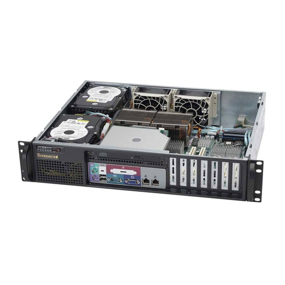
- Page 3 SC523 2U chassis. Installa- tion and maintenance should be performed by experienced technicians only. Supermicro’s SC523 2U chassis features a unique and highly-optimized design. The chassis is equipped with a redundant 410 or 520 Watt, high-efficiency power supply.
-
Page 4: Manual Organization
SC523 Chassis Manual Manual Organization Chapter 1: Introduction The first chapter provides a checklist of the main components included with this chassis and describes the main features of the SC523 chassis. This chapter also includes contact information. Chapter 2: System Safety This chapter lists warnings, precautions, and system safety. - Page 5 Preface Appendices This section lists compatible cables, power supply specifications, and compatible backplanes. Not all compatible backplanes are listed. Refer to our Web site for the latest compatible backplane information. Appendix A: Chassis Cables Appendix B: Power Supply Specifications...
-
Page 6: Table Of Contents
Table of Contents Chapter 1 Introduction Overview ......................1-1 Shipping List ....................1-1 Part Numbers ....................1-1 Contacting Supermicro ..................1-2 Chapter 2 System Safety Overview ......................2-1 Warnings and Precautions ................2-1 Electrical Safety Precautions ................2-1 General Safety Precautions ................2-3 Chapter 3 Chassis Components Overview ...................... - Page 7 Preface Permanent and Optional Standoffs ..............5-9 Motherboard Installation .................. 5-9 Checking the System's Air Flow ..............5-12 System Fans ....................5-13 5-10 Power Supply ....................5-14 Power Supply Replacement ................5-14 Chapter 6 Rack Installation Overview ......................6-1 Unpacking the System ..................6-1 Preparing for Setup ..................
- Page 8 SC523 Chassis Manual Notes viii...
-
Page 9: Chapter 1 Introduction
Chapter 1 Introduction Overview Supermicro’s SC523 2U chassis features a unique and highly-optimized design. The chassis is equipped with high-efficiency power supply. High performance fans provide ample optimized cooling. Two fixed 3.5" drives offer maximum storage capacity in a 2U form factor. -
Page 10: Contacting Supermicro
Super Micro Computer, Inc. 980 Rock Ave. San Jose, CA 95131 U.S.A. Tel: +1 (408) 503-8000 Fax: +1 (408) 503-8008 Email: marketing@supermicro.com (General Information) support@supermicro.com (Technical Support) Web Site: www.supermicro.com Europe Address: Super Micro Computer B.V. Het Sterrenbeeld 28, 5215 ML... -
Page 11: Chapter 2 System Safety
Chapter 2: System Safety Chapter 2 System Safety Overview This chapter provides a quick setup checklist to get your chassis up and running. Following the steps in order given should enable you to have your chassis set up and operational within a minimal amount of time. This quick setup guide assumes that you are an experienced technician, famailiar with common concepts and ter- minology. - Page 12 SC523 Chassis Manual • Be aware of the locations of the power on/off switch on the chassis as well as the room’s emergency power-off switch, disconnection switch or electrical outlet. If an electrical accident occurs, you can then quickly remove power from the system.
-
Page 13: General Safety Precautions
Chapter 2: System Safety General Safety Precautions • Keep the area around the chassis clean and free of clutter. • Place the chassis top cover and any system components that have been re- moved away from the system or on a table so that they won’t accidentally be stepped on. - Page 14 SC523 Chassis Manual • Handle a board by its edges only; do not touch its components, peripheral chips, memory modules or contacts. • When handling chips or modules, avoid touching their pins. • Put the serverboard and peripherals back into their antistatic bags when not in use.
-
Page 15: Chapter 3 Chassis Components
Components Chassis The chassis includes one slim DVD-ROM or CD-ROM, and two 3.5" fixed hard drives. For the latest shipping lists, visit our Web site at: http://www.supermicro. com. Fans The SC523 chassis accepts two system fans. System fans for the SC523 chassis are powered from the serverboard. -
Page 16: Air Shroud
Supermicro Authorized Distributors / System Integrators / Resellers. A list of Supermicro Authorized Distributors / System Integrators /Reseller can be found at: http://www.supermicro.com. Click the Where... -
Page 17: Chapter 4 System Interface
Chapter 4: System Interface Chapter 4 System Interface Overview This chasis includes LEDs on the control panel and drive carriers that indicate the activity and health of specific components. Control Panel Buttons There are two buttons located on the front of the chassis: a reset button and a power on/off button. -
Page 18: Control Panel Leds
SC523 Chassis Manual • Reset: The reset button is used to reboot the system. Control Panel LEDs The control panel located on the front of the SC523 chassis has five LEDs. These LEDs provide you with critical information related to different parts of the system. This section explains what each LED indicates when illuminated and any corrective action you may need to take. - Page 19 Chapter 4: System Interface If the chassis cover is not aligned correctly, the airflow may be disrupted. This leads to overheating. Confirm that the chassis cover is placed correctly. This LED will remain active as long as the overheat condition exists. •...
-
Page 20: Drive Carrier Leds
SC523 Chassis Manual • HDD: Indicates IDE channel activity. SAS/SATA drive, SCSI drive, and/or DVD- ROM or CD-ROM drive activity when flashing. • Power: Indicates power is being supplied to the system's power supply units. This LED should normally be illuminated when the system is operating. Drive Carrier LEDs Your chassis uses SAS/SATA or SCSI drives, but not both. -
Page 21: Chapter 5 Chassis Setup And Maintenance
Chapter 5: Chassis Setup and Maintenance Chapter 5 Chassis Setup and Maintenance Overview This chapter covers the steps required to install components and perform main- tenance on the chassis. The only tools you will need to install components and perform maintenance is a Phillips screwdriver and under certain circumstances, a hex wrench Print this page to use as a reference while setting up your chassis. -
Page 22: Removing The Chassis Cover
SC523 Chassis Manual Removing the Chassis Cover Figure 5-1: Removing the Chassis Cover Removing the Chassis Cover Remove the four screws holding the chassis cover in place. Slide the cover toward the rear of the chassis and lift the cover from the unit. Warning: Except for short periods of time, do NOT operate the server without the cover in place. -
Page 23: Removing And Installing The Air Shroud
Chapter 5: Chassis Setup and Maintenance Removing and Installing the Air Shroud Air Shroud Figure 5-2: Removing the Air Shroud Air shrouds concentrate airflow to maximize fan efficiency. The SC523 chassis air shroud does not require screws to set it up. The air shroud must be removed before a motherboard may be installed. -
Page 24: Removing And Installing Hard Drives
SC523 Chassis Manual Removing and Installing Hard Drives Hard Drives Figure 5-3: Locating the Hard Drives within the Chassis Removing the Hard Drive and Hard Drive Tray from the Chassis Disconnect the chassis from any power source. Disconnect the wiring to the hard drive. Locate the hard drive that needs to be replaced within the chassis. - Page 25 Chapter 5: Chassis Setup and Maintenance Figure 5-4: Removing the Hard Drive Tray from the Chassis Remove the mounting screws holding the hard drive tray into the chassis, and set them aside for later use. Carefully lift the hard drive tray and hard drive from the chassis. Warning: Except for short periods of time (while swapping hard drives), do not operate the server with the hard drives empty.
- Page 26 SC523 Chassis Manual Hard Drive Drive Tray Mounting Screws Figure 5-5: Removing the Hard Drive from the Drive Tray Remove the mounting screws holding the hard drive into the hard drive tray and set them aside for later use. Carefully remove the hard drive from the hard drive tray. Installing a Hard Drive into the Hard Drive Tray Install a new hard drive into the hard drive tray with the printed circuit board side facing down so that the mounting holes align with those in the carrier.
-
Page 27: Removing And Installing The Dvd Or Cd-Rom
Chapter 5: Chassis Setup and Maintenance Removing and Installing the DVD or CD-ROM Prior to installing the motherboard, the DVD or CD-ROM must be removed, then reinstalled after the motherboard has been installed in the chassis. Mounting Screws Figure 5-6: I/O Removing the DVD or CD-ROM Removing the DVD or CD-ROM Drive Locate and remove the screws holding the DVD-ROM in place, setting aside the screws for later use. -
Page 28: Installing The Motherboard
SC523 Chassis Manual Installing the Motherboard This section describes how to install the motherboard to the chassis. To do this, you are required to remove the air shroud, hard drive, hard drive tray and DVD or CD-ROM drive prior to installing the motherboard. See the previous sections for instructions on how to remove these components. -
Page 29: Permanent And Optional Standoffs
Chapter 5: Chassis Setup and Maintenance Flat head Round head Round head Pan head 6-32 x 5 mm 2.6 x 5 mm 3 x 5 mm 6-32 x 5 mm Permanent and Optional Standoffs [0.197] [0.197] [0.197] [0.197] RAIL Standoffs prevent short circuits by securing space between the motherboard and the chassis surface. - Page 30 SC523 Chassis Manual Figure 5-8: Installing the Motherboard Secure the CPU(s), heatsinks, and other components to the motherboard as described in the motherboard documentation. Connect the cables between the motherboard, backplane, chassis, front pan- el, and power supply, as needed. Also, the fans may be temporarily removed to allow access to the backplane ports.
- Page 31 Chapter 5: Chassis Setup and Maintenance Add-on Card/Expansion Slot Setup Slot Cover Add-on/Expansion Card Slots Figure 5-9: Remove the Add-on Card Slot screw SC523 chassis include seven slots for add-on cards and expansion cards. Installing Add-on or Expansion Cards: Confirm that each add on card you are installing includes a standard L- bracket.
- Page 32 SC523 Chassis Manual Figure 5-10: Securing the Add-On/Expansion Card within the Chassis Connect the add-on cards and/or expansion cards to the mother board. Fol- low add-on card manufacturer's instructions. Secure each card to the chassis using the card's L-bracket and the screw previously removed.
-
Page 33: Checking The System's Air Flow
Chapter 5: Chassis Setup and Maintenance Checking the System's Air Flow Proper airflow allows the chassis to keep the server components cooled and prevent damage. Use the following steps to check airflow after setup and in the unlikely event the chassis needs to be serviced. Checking the Server's Air Flow Make sure that no cables or foreign objects obstruct air flow through the chassis. -
Page 34: System Fans
SC523 Chassis Manual System Fans The SC523 chassis includes two fans for cooling and air circulation. System Fans Figure 5-10: Placing the System Fans Replacing a System Fan If necessary, open the chassis while the power is running to determine which fan needs replacing. -
Page 35: 5-10 Power Supply
Power Supply Replacement The SC523 chassis models includes one power supply. Replacement units can be ordered directly from Supermicro (see contact information in the Preface). Removing the Power Supply Disconnect the chassis from the power source. Remove the screws on the power supply panel, on the back of the chassis as illustrated. - Page 36 SC523 Chassis Manual Figure 5-12: Removing the Power Supply Remove the screws holding the power supply bracket to the rear of the power supply and set them aside for later use. Remove the power supply bracket. Gently pull the power supply out of the chassis. 5-16...
- Page 37 Chapter 5: Chassis Setup and Maintenance Figure 5-12: Removing the Power Supply 5-17...
-
Page 38: Chapter 6 Rack Installation
Chapter 6: Rack Installation Chapter 6 Rack Installation Overview This chapter provides a quick setup checklist to get your chassis up and running. Following these steps in the order given should enable you to have the system operational within a minimum amount of time. Unpacking the System You should inspect the box the chassis was shipped in and note if it was damaged in any way. -
Page 39: Choosing A Setup Location
SC523 Chassis Manual Choosing a Setup Location • Leave enough clearance in front of the rack to enable you to open the front door completely (~25 inches). • Leave approximately 30 inches of clearance in the back of the rack to allow for sufficient airflow and ease in servicing. -
Page 40: Rack Mounting Considerations
Chapter 6: Rack Installation • Use a regulating uninterruptible power supply (UPS) to protect the server from power surges, voltage spikes and to keep your system operating in case of a power failure. • Allow the hot plug hard drives and power supply modules to cool before touching them. -
Page 41: Rack Mounting Instructions
SC523 Chassis Manual Rack Mounting Instructions This section provides information on installing the SC523 chassis into a rack unit with the rails provided. There are a variety of rack units on the market, which may mean the assembly procedure will differ slightly. You should also refer to the instal- lation instructions that came with the rack unit you are using. -
Page 42: Outer Rack Rails
Chapter 6: Rack Installation Secure to the Front of the Rack Secure to the Rear of the Rack Attach Outer Racks together Figure 6-1. Assembling the Outer Rails Outer Rack Rails Outer rails attach to the server rack and hold the server in place. The outer rails for the SC523 chassis extend between 26"... - Page 43 SC523 Chassis Manual Figure 6-2: Installing the Rack Rails Installing the Chassis into a Rack Confirm that chassis includes the inner rails and rail extensions. Also, confirm that the outer rails are installed on the rack. Line chassis rails with the front of the rack rails. Slide the chassis rails into the rack rails, keeping the pressure even on both sides (you may have to depress the locking tabs when inserting).
-
Page 44: Appendix A Sc523 Chassis Cables
A variety of cables are supported for your chassis system. In order to obtain the most up-to-date information on compatible cables, compoments and configurations, refer to the manufacturer of the motherboard you are using and to our Web site at: www.supermicro.com. SC523L-410B Part #... - Page 45 SC523 Chassis Manual A-3 Compatible Cables These cables are compatible with the SC523 Chassis. Alternate SAS/SATA Cables Some compatible motherboards have different connectors. If your motherboard has only one SAS connector that the SAS/SATA cables must share, use one of the following cables.
-
Page 46: Extending Power Cables
Appendix A: Chassis Cables Extending Power Cables Although Super Micro chassis are designed with to be efficient and cost-effective, some compatible motherboards have power connectors located in different areas. To use these motherboards you may have to extend the power cables to the mother boards. - Page 47 SC523 Chassis Manual A-5 Chassis Screws The accessory box includes all the screws needed to setup your chassis. This section include descriptions of the most common screws used. Your chassis may not require all the parts listed. HARD DRIVE Flat head Pan head 6-32 x 5 mm 6-32 x 5 mm...
-
Page 48: Appendix B Sc523 Power Supply Specifications
Appendix B: Power Supply Specifications Appendix B SC523 Power Supply Specifications This appendix lists power supply specifications for your chassis system. SC523L-410B 410W (Redundant) MFR Part # PWS-0061 Voltage Range: -36 to -72V Nominal Voltage: -.48V Rated DC Voltage Max Input Current: 18A @ -48V 9.5 - 4.5 Amp... - Page 49 SC523 Chassis Manual Notes...