Table of Contents
Advertisement
Available languages
Available languages
Operator Manual
ELECTRIC GENERATOR • GROUPE ELECTROGENE • GENERADOR ELECTRICO
IMPORTANT – Please make certain
that persons who are to use this
equipment thoroughly read and
understand these instructions and
any additional instructions provided
prior to operation.
Record the serial number as
indicated on your Generator's
nameplate:
Serial No.______________________
DO NOT RETURN TO
STOP
STORE!
CALL US FIRST!
CUSTOMER HOTLINE
1-800-445-1805
FOR QUESTIONS OR
SERVICE INFORMATION
www.powermate.com
Manuel de l'opérateur
•
IMPORTANT - Prière de vous assurer
que les personnes destinées à
utiliser cet appareil ont pris soin d'en
lire et d'en comprendre le mode
d'emploi ou les directives avant de le
mettre en marche.
Enregistrer le numéro de série
figurant sur la plaque signalétique
du groupe électrogène:
Nº de série ____________________
NE PAS RETOURNER
ARRÊT
AU MAGASIN!
APPELEZ–NOUS D'ABORD!
ASSISTANCE
TELEPHONIQUE
A LA CLIENTELE
1-800-445-1805
POUR L'INFORMATION DE
QUESTIONS OU SERVICE
•
Manual del operador
PM0105007
IMPORTANTE - Asegúrese que las
personas que utilizarán este equipo
lean y entiendan completamente
estas instrucciones y cualquier
instrucción adicional proporcionada
antes del funcionamiento.
Registre de serie como se indica
en la placa del nombre de su
generador:
No. de serie ___________________
NO LO DEVUELVA A
ALTO
LA TIENDA!
¡PRIMERO LLÁMENOS!
LÍNEA DIRECTA DE
ATENCIÓN AL CLIENTE
1-800-445-1805
PARA la INFORMACION de
PREGUNTAS O SERVICIO
09/10 0068208
Advertisement
Table of Contents

Related Manuals for Powermate PM0105007


Summary of Contents for Powermate PM0105007
- Page 1 • Manual del operador Operator Manual • ELECTRIC GENERATOR • GROUPE ELECTROGENE • GENERADOR ELECTRICO PM0105007 IMPORTANT – Please make certain IMPORTANT - Prière de vous assurer IMPORTANTE - Asegúrese que las that persons who are to use this que les personnes destinées à...
-
Page 2: Table Of Contents
TABLE OF CONTENTS Safety and operation rules ......3 Spark plug ........11 Spark arresting muffler . -
Page 3: Safety And Operation Rules
SAFETY INFORMA TION SAFETY INFORMA TION CAUTION indicates a potentially WARNING indicates a DANGER indicates a potentially hazardous situation which, if not potentially hazardous situation hazardous situation which, if not avoided, may result in minor or which, if not avoided, could avoided, WILL result in death or moderate personal injury, or result in death or serious injury. -
Page 4: Spark Arresting Muffler
d. Do not refuel near open flames, pilot lights, or ARRESTER ARRESTER sparking electrical equipment such as power tools, welders, and grinders. YOUR PRODUCT MAY NOT BE EQUIPPED WITH e. The muffler and air cleaner must be installed A SPARK ARRESTING MUFFLER. If the product will be and in good condition at all times as they used around flammable materials, such as agricultural crops, function as flame arresters if backfiring occurs. -
Page 5: Operating Voltage
To avoid backfeeding into utility systems, isolation of the OPERA TING VOL OPERA TING VOL residence electrical system is required. Before temporary connection of the generator to the residence electrical system, turn off the main service/disconnect. CAUTION: Operating voltage and frequency If your generator is to be used as a stand-by power source requirement of all electronic equipment should be in case of utility power failure, it should be installed by a... -
Page 6: Before Operation
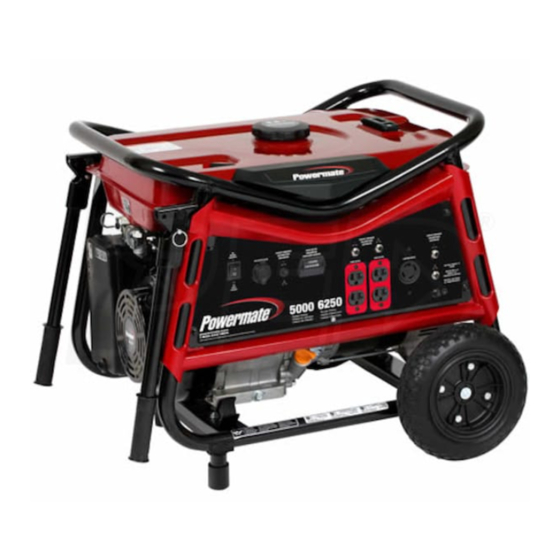
LUBRICATION BEFORE OPERA TION BEFORE OPERA TION DO NOT attempt to start this engine without filling the crank case with the proper amount and type of oil. Your GROUND FAULT CIRCUIT INTERRUPTER (GFCI) generator has been shipped from the factory without oil in the PROTECTION crankcase. - Page 7 GENERA OR FEA TURES GENERA OR FEA TURES A. Control Panel E. Ground Terminal NOTE: Total power drawn from all receptacles must not exceed the nameplate ratings. F. Hour Meter B. 120 V, 20 Ampere Receptacle G. Engine On/Off Switch 20 amps of current may be drawn from the receptacle.
-
Page 8: Generator Features
GENERA OR FEA TURES - DC USAGE GENERA OR FEA TURES - DC USAGE Q. DC Usage This Generator is equipped with a cigarette lighter style 12V DC receptacle. The maximum draw for this DC outlet is 8.3 Amps. The 12V DC receptacle is not intended for use to charge automotive batteries. -
Page 9: Portability Kit Installation
PORT ABILITY KIT INST ALLA TION PORT ABILITY KIT INST ALLA TION PORTABILITY KIT PART NUMBER: 0068294 TOOLS REQUIRED: 10mm and 13mm sockets and ratchets, block(s) of wood (minimum of 6” tall). WHEEL INSTALLATION 1. Block up the alternator end of generator to install wheel kit. 2. -
Page 10: Starting The Unit
ARTING THE UNIT ARTING THE UNIT • Provide adequate ventilation for toxic exhaust gases and cooling air flow. Gasoline is very dangerous. • Do not start or run the generator in an enclosed Serious injury or death may result from fire caused area, even if door or windows are open. -
Page 11: Periodic Maintenance
PERIODIC MAINTENANCE PERIODIC MAINTENANCE Daily (Before Initial Every Every ITEM NOTES operation) 20 hours 50 hours 100 hours Check condition. Adjust gap and Spark Plug clean. Replace if necessary. Engine Oil Check oil level. Replace. Air Filter Clean, replace if necessary. Clean fuel filter and fuel tank strainer. -
Page 12: Brushes
GENERATOR: Brushes QUICK STARTING TIPS FOR UNITS THAT HAVE The brushes in the generator should be inspected once BEEN SITTING FOR AWHILE: every year for chips and cracks. Brushes should be replaced If your unit has been sitting around for a long time period when they are worn to 1/4 inch (7mm). -
Page 13: Engine Troubleshooting
ENGINE TROUBLESHOOTING ENGINE TROUBLESHOOTING ENGINE SPECIFICA TIONS ENGINE SPECIFICA TIONS Type .......4-stroke, single cylinder, gasoline, OHV Displacement . -
Page 14: Service Information
· If a separate operator's manual and engine warranty or at www.powermate.com from the engine manufacturer is included with this product, only that warranty will apply to the engine. to obtain warranty service ·... -
Page 15: Régles D'opération Et De Sécurité
SÉCURITÉ SÉCURITÉ L'AVERTISSEMENT Indique une DANGER signifie une situation La mention ATTENTION sert à situation présentant un danger susceptible de présenter un danger prévenir l'utilisateur d'un danger potentiel et qui, en l'absence potentiel qui risque d'occasionner qui, s'il n'est pas évité, d'intervention, pourrait conduire à... -
Page 16: Silencieux Pare-Étincelles
DANGER - RISQUE D'ÉMISSION DE d’empêcher les fuites. MONOXYDE DE CARBONE : L'échappement des moteurs contient du 22.Pour transporter l'appareil d’un site à l’autre, monoxyde de carbone, un gaz toxique, utilisez les bonnes techniques de levage sinon inodore et invisible qui, s'il est respiré, peut vous pourriez vous blesser. -
Page 17: Vérifier La Tension
5. La puissance nominale du générateur devrait être égale ou INST ALLA TION INST ALLA TION supérieure au nombre total de watts nécessaires au fonctionnement de l'équipement à alimenter. 6. Branchez toujours d’abord la charge la plus lourde au générateur, puis ajoutez les les autres une à une. VÉRIFIER LA TENSION VÉRIFIER LA... -
Page 18: Avant De Mettre En Marche
LUBRIFICATION ANT DE METTRE EN MARCHE ANT DE METTRE EN MARCHE NE PAS essayer de faire démarrer le moteur avant d’avoir rempli le carter d’huile, en utilisant la quantité et le type PROTECTION AVEC DISJONCTEUR DIFFÉRENTIEL d’huile appropriés. Le groupe électrogène est expédié de l'u- (GFCI) sine avec le carter vide. -
Page 19: Caractéristiques Du Groupe Electrogene
CARACTÉRISTIQUES DU GROUPE ELECTROGENE CARACTÉRISTIQUES DU GROUPE ELECTROGENE A. Tableau de commande E. Borne de Mise à Terre NOTE : Le total charge dessiné de toutes prises ne doit pas dépasser les limites indiquées de plaque. F. Horomètre B. Prise de 120 V, 20 A G. -
Page 20: Utilisation De Courant Continu (C.c.)
CARACTÉRISTIQUES DU GROUPE ELECTROGENE - CARACTÉRISTIQUES DU GROUPE ELECTROGENE - UTILISA UTILISA TION DE COURANT CONTINU (C.C.) TION DE COURANT CONTINU (C.C.) Utilisation de courant continu (c.c.) Cet alternateur est muni d'une prise c.c. de 12 volts de type allume-cigarette. Le courant maximal de cette prise c.c. est de 8,3 ampères. -
Page 21: L'installation De Kit De Transport
L'INST ALLA TION DE KIT DE TRANSPORT L'INST ALLA TION DE KIT DE TRANSPORT LE NOMBRE DE PARTIE DE KIT DE TRANSPORT: 0068294 OUTILS NÉCESSAIRES : Cliquet à rochet de 10mm et 13mm, blocs de bois (minimum de 6 po de hauteur) INSTALLATION DES ROUES 1. -
Page 22: Démarrage De L'appareil
DEMARRAGE DE L'APP AREIL DEMARRAGE DE L'APP AREIL • Fournir une aération suffisante pour éliminer les gaz L’essence est un produit très dangereux. Un incendie d’échappement toxiques et assurer le refroidissement résultant du contact de l'essence avec des surfaces chaudes du moteur. -
Page 23: Entretien Périodique
ENTRETIEN PÉRIODIQUE ENTRETIEN PÉRIODIQUE Quotidiennement Initiale Chaque Chaque ARTICLE REMARQUES (Avant de mettre 20 heures 50 heures 100 heures en marche) Bougie Vérifier l'état. Ajuster l'écartement des électrodes et nettoyer. Remplacer selon le besoin. d'allumage Huile à moteur Vérifier le niveau d'huile. Remplacer. -
Page 24: Les Balais
GROUPE ELECTROGENE: Les Balais 3. Remplacer les bougies d'allumage. Les balais du groupe électrogène doivent être inspectés une fois par an pour vérifier s’ils ne sont pas fendillés ou 4. Vérifier les canalisations d'huile et veiller à ce que le autrement abîmés. -
Page 25: Depannage Du Moteur
ANNAGE DU MOTEUR ANNAGE DU MOTEUR CARACTERISTIQUES DU MOTEUR CARACTERISTIQUES DU MOTEUR Type ......A quatre temps, à un cylindre, à essence, OHV Cylindrée . -
Page 26: Service Clientèle
Si le produit est utilisé à des www.powermate.com. fins d'affaires ou commerciales, la période couverte par la garantie se limite à Un (1) an à partir de la date d'achat. En ce qui concerne l'entretien couvert par la garantie, le client doit COMMANDE DE PIÈCES DE RECHANGE... -
Page 27: Reglas De Seguridad Y De Funcionamiento
SEGURIDAD SEGURIDAD PRECAUCIÓN indica una situación PELIGRO indica una situación ADVERTENCIA indica una situación de peligro potencial, la potencialmente de riesgo, la cual, si potencialmente peligrosa que, si cual, si no se evita, podría ocasionar no se evita, puede ocasionar no se evita, PROVOCARÁ... -
Page 28: Silenciador Apagachispas
b.Buena ventilación para el enfriamiento. La 23. Para evitar quemaduras, no toque el silenciador circulación de aire y las temperaturas son del motor u otras superficies del generador que importantes para las unidades enfriadas por se hayan calentado durante la operación. aire. -
Page 29: Requerimiento De Voltaje
Para evitar la retro-alimentación a los sistemas de REQUERIMIENT O DE VOL REQUERIMIENT O DE VOL suministro, se requiere el aislamiento del sistema eléctrico residencial. Antes de realizar la conexión temporal del generador hacia el sistema eléctrico residencial, apague o desconecte el servicio principal. -
Page 30: Antes De La Operacion
LUBRICACION ANTES DE LA OPERACION ANTES DE LA OPERACION NO intente arrancar este motor sin llenar el cárter con la cantidad y el tipo de aceite adecuados. Su generador ha sido PROTECCIÓN DE INTERRUPTOR DE CIRCUITO DE enviado de fábrica sin aceite en el cárter. El operar la unidad FALLA DE CONEXIÓN A TIERRA (GFCI, por sus siglas sin aceite puede arruinar el motor. -
Page 31: Caracteristicas Del Generador
CARACTERISTICAS DEL GENERADOR CARACTERISTICAS DEL GENERADOR A. Panel de control Terminal del Tierra NOTA: El carga total dibujado de todos receptáculos no debe exceder los valores nominales de la placa de identificación. Contador Horario Receptáculo de 120 voltios, 20 amperes El motor On/Off (En/De) Interruptor 20 amperes de la corriente se pueden dibujar del receptáculo. -
Page 32: Uso De Dc
CARACTERISTICAS DEL GENERADOR - USO DE DC CARACTERISTICAS DEL GENERADOR - USO DE DC Uso de DC Este generador está equipado con un receptáculo de DC de 12V tipo encendedor. La extracción máxima para este tomacorriente de DC es de 8.3 amperios. El receptáculo de DC de 12V no está... -
Page 33: Instalacion Del Juego De Transport
INST ALACION DEL JUEGO DE TRANSPORT INST ALACION DEL JUEGO DE TRANSPORT NUMERO de PARTE de JUEGO de TRANSPORT: 0068294 HERRAMIENTAS NECESARIAS: Cubos y trinquetes de 10mm y 13mm, bloque(s) de madera, mínimo de 6” de alto. INSTALACIÓN DE LAS RUEDAS 1. -
Page 34: Arranque De La Unidad
ARRANQUE DEL UNIDAD ARRANQUE DEL UNIDAD • Debe suministrar una ventilación adecuada para los gases tóxicos de escape y el flujo de La gasolina es muy peligrosa. Si la gasolina hace aire refrigerante. contacto con superficies calientes puede ocasionar • No encienda o arranque el generador en un lesiones serias o la muerte. -
Page 35: Mantenimiento Periódico
MANTENIMIENT O PERIÓDICO MANTENIMIENT O PERIÓDICO Diariamente Inicial Cada Cada ARTÍCULO NOTAS (Antes de la 20 horas 50 horas 100 horas operacion) Revise en qué condición se encuentra. Ajuste el Bujía espacio y límpiela. Reemplácela, si fuera necesario. Revise el nivel de aceite. Aceite del motor Cámbielo. -
Page 36: Escobillas
GENERADOR: Escobillas 3. Cambie la bujía de encendido. Las escobillas del generador deben ser inspeccionadas una vez por año para verificar que no estén rajadas o 4. Verifique los conductos de combustible. Asegúrese de resquebrajadas. Las escobillas deben reemplazarse cuando se que esté... -
Page 37: Deteccion De Fallos Del Motor
DETECCION DE F ALLOS DEL DETECCION DE F ALLOS DEL ESPECIFICACIONES DEL ESPECIFICACIONES DEL Tipo ....... 4 carreras, cilindro único, gasolina, OHV Desplazamiento . -
Page 38: Informacion De Servicio Al Cliente
1-800-445-1805 reparados o de reemplazo al consumidor; estos cargos los deberá cubrir el cliente. o en www.powermate.com · Si un manual separado de operario y garantía de motor del fabricante de motor se incluyen con este producto, sólo para obtener información sobre el... -
Page 39: Emission Control Warranty
NOTES – REMARQUES – NOTAS Customer Hotline 1-800-445-1805... -
Page 40: Parts Drawings And Parts List
ARTS DRA WING / SCHEMA DES PIÈCES / DIAGRAMA DE PIEZAS - PM0105007 ARTS DRA WING / SCHEMA DES PIÈCES / DIAGRAMA DE PIEZAS - PM0105007 Customer Hotline 1-800-445-1805... - Page 41 ARTS LIST / LISTE DES PIÈCES / LIST DE PIEZAS - PM0105007 ARTS LIST / LISTE DES PIÈCES / LIST DE PIEZAS - PM0105007 REF. PART DESCRIPTION DESCRIPTION DESCRIPCIÓN 0068301 Frame Cadre Marco 0067208 Isolator left Sectionneur gauche Aislador izquierda...
- Page 42 ENGINE DRA WING / SCHEMA DE MOTEUR / DIAGRAMA DE MOT ENGINE DRA WING / SCHEMA DE MOTEUR / DIAGRAMA DE MOT Customer Hotline 1-800-445-1805...
- Page 43 ENGINE P ENGINE P ARTS LIST / LISTE DES PIÈCES DU MOTEUR / LIST ARTS LIST / LISTE DES PIÈCES DU MOTEUR / LIST DE PIEZAS DEL DE PIEZAS DEL REF. PART DESCRIPTION DESCRIPTION DESCRIPCIÓN 0068293 Engine 389 cc Moteur 389 cc Motor 389 cc 0068090 Cylinder head assembly...
- Page 44 Powermate® is a registered trademark of Pramac America, LLC. © 2010 Pramac America, LLC. Tous droits réservés. Powermate® est une marque déposée de Pramac America, LLC. © 2010 Pramac America, LLC. Reservados todos los derechos. Powermate® es una marca comercial registrada de Pramac America, LLC.