Table of Contents
Advertisement
Visit our website at
www.MillerWelds.com
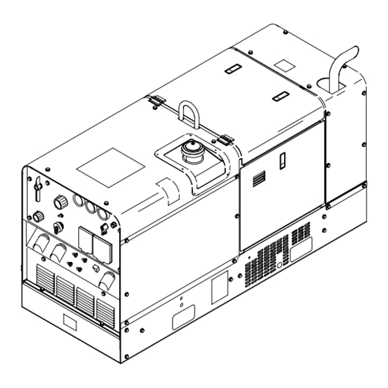
Trailblazer Pro 350
OM-4401
May 2002
Processes
MIG (GMAW) Welding
Flux Cored (FCAW) Welding
Stick (SMAW) Welding
TIG (GTAW) Welding
Air Plasma Cutting and Gouging
with Spectrum
Air Carbon Arc (CAC-A) Cutting
and Gouging
Description
Engine Driven Welding Generator
R
198 521M
R
Unit
Advertisement
Table of Contents
Troubleshooting

Related Manuals for Miller Electric Trailblazer Pro 350


Summary of Contents for Miller Electric Trailblazer Pro 350
- Page 1 MIG (GMAW) Welding Flux Cored (FCAW) Welding Stick (SMAW) Welding TIG (GTAW) Welding Air Plasma Cutting and Gouging with Spectrum Unit Air Carbon Arc (CAC-A) Cutting and Gouging Description Engine Driven Welding Generator Trailblazer Pro 350 Visit our website at www.MillerWelds.com...
- Page 2 Welding Process Manuals such as SMAW, GTAW, GMAW, and GMAW-P. Miller Electric manufactures a full line of welders and welding related equipment. For information on other quality Miller products, contact your local Miller distributor to receive the latest full line catalog orindividual catalog sheets.
-
Page 3: Table Of Contents
TABLE OF CONTENTS SECTION 1 – SAFETY PRECAUTIONS - READ BEFORE USING ......1-1. Symbol Usage . -
Page 5: Section 1 - Safety Precautions - Read Before Using
SECTION 1 – SAFETY PRECAUTIONS - READ BEFORE USING rom _nd_4/02 1-1. Symbol Usage Means Warning! Watch Out! There are possible hazards with this procedure! The possible hazards are shown in the adjoining symbols. This group of symbols means Warning! Watch Out! possible Y Marks a special safety message. -
Page 6: Engine Hazards
WELDING can cause fire or explosion. HOT PARTS can cause severe burns. D Allow cooling period before maintaining. Welding on closed containers, such as tanks, D Wear protective gloves and clothing when drums, or pipes, can cause them to blow up. Sparks working on a hot engine. -
Page 7: Additional Symbols For Installation, Operation, And Maintenance
BATTERY ACID can BURN SKIN and MOVING PARTS can cause injury. EYES. D Keep away from fans, belts, and rotors. D Do not tip battery. D Keep all doors, panels, covers, and guards D Replace damaged battery. closed and securely in place. D Flush eyes and skin immediately with water. -
Page 8: Principal Safety Standards
H.F. RADIATION can cause interference. ARC WELDING can cause interference. D High-frequency (H.F.) can interfere with radio D Electromagnetic energy can interfere with navigation, safety services, computers, and sensitive electronic equipment such as communications equipment. computers and computer-driven equipment D Have only qualified persons familiar with such as robots. -
Page 9: Section 1 - Consignes De Sécurité - Lire Avant Utilisation
SECTION 1 – CONSIGNES DE SÉCURITÉ – LIRE AVANT UTILISATION rom _nd_fre 11/98 1-1. Signification des symboles Signifie Mise en garde ! Soyez vigilant ! Cette procédure présente des risques de danger ! Ceux-ci sont identifiés par des symboles adjacents aux directives. Ce groupe de symboles signifie Mise en garde ! Soyez vigilant ! Il y a des Y Identifie un message de sécurité... -
Page 10: Dangers Existant En Relation Avec Le Moteur
LE SOUDAGE peut provoquer un in- DES PIÈCES CHAUDES peuvent cendie ou une explosion. provoquer des brûlures graves. D Prévoir une période de refroidissement avant d’effec- Le soudage effectué sur des conteneurs fermés tels que tuer des travaux d’entretien. des réservoirs, tambours ou des conduites peut provoquer D Porter des gants et des vêtements de protection pour leur éclatement. -
Page 11: Dangers Supplémentaires En Relation Avec L'installation, Le Fonctionnement Et La Maintenance
DES ORGANES MOBILES peuvent L’ACIDE DE LA BATTERIE peut pro- provoquer des blessures. voquer des brûlures dans les YEUX et sur la PEAU. D Ne pas approcher les mains des ventilateurs, cour- roies et autres pièces en mouvement. D Ne pas renverser la batterie. D Maintenir fermés et fixement en place les portes, D Remplacer une batterie endommagée. -
Page 12: Principales Normes De Sécurité
LE RAYONNEMENT HAUTE FRÉ- LE SOUDAGE À L’ARC risque de QUENCE (H.F.) risque de provoquer provoquer des interférences. des interférences. D L’énergie électromagnétique risque de provoquer des interférences pour l’équipement électronique D Le rayonnement haute fréquence (H.F.) peut sensible tel que les ordinateurs et l’équipement com- provoquer des interférences avec les équipements mandé... -
Page 13: Section 2 - Definitions
SECTION 2 – DEFINITIONS 2-1. Symbol Definitions Fast Fast/Slow Stop Engine Slow (Idle) (Run, Weld/Power) (Run/Idle) Start Engine Panel/Local Temperature Fuel Check Valve Engine Oil High Temperature Battery (Engine) Clearance Engine Glow Plug Amperes Volts MIG (GMAW), Stick (SMAW) TIG (GTAW) Circuit Breaker Wire Electrode... -
Page 14: Dimensions, Weights, And Operating Angles
3-2. Dimensions, Weights, and Operating Angles Dimensions 36 in (914 mm) Height (to top of exhaust) Y Do not exceed tilt angles or engine could Width 24 in (610 mm) be damaged or unit could tip. Depth 59-1/2 in (1511 mm) Y Do not move or operate unit where it could Y Do not move or operate unit where it could tip. -
Page 15: Duty Cycle And Overheating
3-4. Duty Cycle And Overheating Duty Cycle is percentage of 10 min- utes that unit can weld at rated load without overheating. Y Exceeding duty cycle can damage unit void warranty. % DUTY CYCLE 60% Duty Cycle at 350 Amperes DC 6 Minutes Welding 4 Minutes Resting 198 919... -
Page 16: Cc Stick Volt-Ampere Curves
3-6. CC Stick Volt-Ampere Curves Volt-ampere curves show minimum and maximum voltage and amper- A. CC/DC Stick Mode age output capabilities of unit. Curves of other settings fall be- tween curves shown. DC AMPERES B. CC/AC Stick Mode AC AMPERES 203 111 / 203 110 OM-4401 Page 12... -
Page 17: Cc Tig Volt-Ampere Curves
3-7. CC TIG Volt-Ampere Curves Volt-ampere curves show minimum and maximum voltage and amper- age output capabilities of unit. Curves of other settings fall be- tween curves shown. A. CC/AC TIG Mode AC AMPERES B. CC/DC TIG Mode DC AMPERES 203 113 / 203 114 OM-4401 Page 13... -
Page 18: Dc/Cv Mig Volt-Ampere Curves
3-8. DC/CV MIG Volt-Ampere Curves Volt-ampere curves show minimum and maximum voltage and amper- age output capabilities of unit. Curves of other settings fall be- tween curves shown. DC AMPERES 203 112 SECTION 4 – INSTALLATION 4-1. Installing Welding Generator Y Do not weld on base. -
Page 19: Engine Prestart Checks
4-2. Engine Prestart Checks Remove air bleed screw Check radiator coolant when filling radiator. See level when fluid is low in Section 4-3. recovery tank. Full Full 1/2 in Capacity (13 mm) w/Overflow Tank 6.4 qt (6 L) Full Diesel Full Ref. -
Page 20: Adding Coolant To Radiator
4-3. Adding Coolant To Radiator Y Stop engine and let cool. Check coolant level according to Section 4-2 before starting this procedure. If coolant level is below bottom of radiator filler neck, add coolant as Full follows: Radiator Air Bleed Screw Remove radiator air bleed screw. -
Page 21: Installing Exhaust Pipe
4-5. Installing Exhaust Pipe Point exhaust pipe in desired direction but always away from front panel and direction of travel. Tools Needed: 1/2 in 802 173-C / Ref. 203 031-A 4-6. Connecting To Weld Output Terminals Y Do not connect to CC and CV terminals at the same time. -
Page 22: Selecting Weld Cable Sizes
4-7. Selecting Weld Cable Sizes* Weld Cable Size** and Total Cable (Copper) Length in Weld Circuit Not Exceeding*** 150 ft 200 ft 250 ft 300 ft 350 ft 400 ft 100 ft (30 m) or Less (45 m) (60 m) (70 m) (90 m) (105 m) - Page 23 Notes OM-4401 Page 19...
-
Page 24: Section 5 - Operating Welding Generator
SECTION 5 – OPERATING WELDING GENERATOR 5-1. Controls (See Section 5-2) 203 031-A-A / Ref. 802 579-B OM-4401 Page 20... -
Page 25: Description Of Controls (See Section 5-1)
5-2. Description Of Controls (See Section 5-1) Engine Lights Voltmeter (Optional) 14 Engine Speed Switch Use switch to select engine speed. Battery Charging Light Meter displays weld voltage at the weld termi- Place switch in Idle position to lock engine at nals, but not necessarily the welding arc due Light goes on if engine alternator is not charg- idle speed during start-up, and to CC weld at... -
Page 26: Process/Contactor Switch
5-3. Process/Contactor Switch Process/Contactor Switch Y Weld output terminals are en- ergized when Process/Con- tactor switch is in any Elec- trode Hot position and the en- gine is running. Use switch to select weld process and weld output on/off control (see table below and Section 5-5). -
Page 27: Remote Voltage/Amperage Control
5-5. Remote Voltage/Amperage Control Remote 14 Receptacle RC1 Connect optional remote control to RC1 (see Section 4-8). In Example: Example: Combination Remote Amperage Control (Stick) Process = Stick (Using Remote On/Off) Min = 40 A DC Max = 180 A DC Max (180 A DC) Min (40 A DC) Set Remote... -
Page 28: Section 6 - Operating Auxiliary Equipment
SECTION 6 – OPERATING AUXILIARY EQUIPMENT 6-1. Generator Power Receptacles And Circuit Breakers Y If unit does not have GFCI receptacles, use GFCI-pro- tected extension cord. Generator power decreases as weld current increases. 240 V 50 A AC Receptacle RC3 supplies 60 Hz single-phase power at weld/power speed. -
Page 29: Wiring Instructions For Optional 240 Volt, Single-Phase Plug (Nema 14-50P)
6-2. Wiring Instructions For Optional 240 Volt, Single-Phase Plug (NEMA 14-50P) The plug can be wired for a 240 V, 2-wire load or a 120/240V, 3-wire load. See circuit diagram. Plug Wired for 120/240 V, 3-Wire Load Tools Needed: When wired for 120 V loads, each duplex receptacle shares a load with one half of 240 V receptacle. -
Page 30: Routine Maintenance
7-2. Routine Maintenance Note Follow the storage procedure in the engine owner’s manual if the unit will not be used for an extended period. Y Stop engine before maintaining. See also Engine Manual and Maintenance Label. Recycle engine Service engine more often if used in severe condi- fluids. -
Page 31: Servicing Optional Spark Arrestor
500 h Replace fan belt. Flush radiator. FUEL Drain sludge from Repair or replace SLUDGE fuel cracked cables. tank. 800 h Check valve clearance.* 1000 h Blow Service welding generator vacuum inside. brushes and slip rings. Service During heavy more often in dirty conditions.* service, clean monthly. -
Page 32: Servicing Air Cleaner
7-4. Servicing Air Cleaner Y Stop engine. Y Do not run engine without air cleaner or with dirty element. En- gine damage caused by using a damaged element is not covered by the warranty. The air cleaner primary element can be cleaned but the dirt holding capac- ity of the filter is reduced with each cleaning. -
Page 33: Servicing Engine Lubrication And Fuel Systems
7-5. Servicing Engine Lubrication And Fuel Systems FLOW Tools Needed: 9/16 in Ref. 802 579-B / Ref. 203 031-A / S-0842 Y Stop engine and let cool. base. Change engine oil and filter accord- Replace secondary fuel filter according to ing to instructions in engine manual. -
Page 34: Servicing Engine Cooling System
7-6. Servicing Engine Cooling System Y Stop engine and let cool. Radiator Draincock Radiator Cap Radiator Air Bleed Screw Change coolant according to engine manual. Add coolant according to Sec- tion 4-3). Run engine until engine reaches normal operating temperature. Loosen air bleed screw to remove air from cooling system. -
Page 35: Replacing Throttle Solenoid Ts1
7-7. Replacing Throttle Solenoid TS1 Y Stop engine, and let cool. Y Disconnect battery, negative (–) cable first. Remove right side engine panel. Plug PLG11/Receptacle RC11 Throttle Solenoid TS1 Shoulder Bolt And Nut Throttle Link Throttle Solenoid Plunger Rod Jam Nut Throttle Arm Disconnect solenoid plug PLG11 from wiring harness receptacle... -
Page 36: Adjusting Engine Speed
7-8. Adjusting Engine Speed After tuning engine, check engine speeds with a tachometer (see table). If necessary, adjust speeds as follows: 2500 rpm Start engine and run until warm. Turn V/A control to max. 3750 Max Adjusting Idle Speed Turn Engine Control switch to Run/ Idle position. -
Page 37: Overload Protection
7-9. Overload Protection Y Stop engine. Tools Needed: When a circuit breaker opens, 3/8 in it usually indicates a more seri- ous problem exists. Contact Factory Authorized Service Agent. Circuit Breaker CB5 CB5 protects the 24 volt ac output to Remote 14 receptacle RC1. If CB5 opens, 24 volt ac output to RC1 stops. -
Page 38: Troubleshooting
7-10. Troubleshooting A. Welding Trouble Remedy No weld output; generator power output Place Process/Contactor switch in a Electrode Hot position, or place switch in a Remote position and okay. connect remote contactor to optional Remote 14 receptacle RC1 (see Section 4-8). Check position of polarity switch. - Page 39 Trouble Remedy Min or max CV weld output only. Check position of Voltage/Amperage Adjustment control and Voltage/Amperage Adjust switch (see Sec- tion 5-1). Repair or replace remote control device. Have Factory Authorized Service Agent check field current regulator board PC2. Lack of high frequency;...
- Page 40 C. Engine Trouble Remedy Engine will not crank. Reset circuit breaker CB8 (see Section 7-9). Check battery voltage. Check battery connections and tighten if necessary. Have Factory Authorized Service Agent check Engine Control switch S1. Engine cranks, but does not start. Check fuel level (see Section 4-2).
- Page 41 Trouble Remedy Engine does not go to low (idle) speed Be sure Engine Speed switch is in Run/Idle position. with Engine Speed switch in Run/Idle position. Remove all weld and generator power loads. Turn off remote device connected to Remote 14 receptacle RC1 (see Section 4-8). Check for obstructed movement of throttle solenoid linkage.
-
Page 42: Section 8 - Electrical Diagrams
SECTION 8 – ELECTRICAL DIAGRAMS Figure 8-1. Circuit Diagram For Welding Generator OM-4401 Page 38... - Page 43 198 518-A OM-4401 Page 39...
-
Page 44: Section 9 - Run-In Procedure
SECTION 9 – RUN-IN PROCEDURE run_in4 8/01 9-1. Wetstacking Y Do perform run-in procedure at less than 20 volts weld output and do not exceed duty cycle or equip- ment damage may occur. Welding Generator Run diesel engines near rated volt- age and current during run-in period to properly seat piston rings and prevent wetstacking. -
Page 45: Run-In Procedure Using Load Bank
9-2. Run-In Procedure Using Load Bank Y Stop engine. Y Do not touch hot exhaust pipe, engine parts, or load bank/grid. Y Keep exhaust and pipe away from flammables. Y Do perform run-in procedure at less than 20 volts weld output and do not exceed duty cycle or equip- ment damage may occur. -
Page 46: Run-In Procedure Using Resistance Grid
9-3. Run-In Procedure Using Resistance Grid Y Stop engine. Y Do not touch hot exhaust pipe, engine parts, or load bank/grid. Y Keep exhaust and pipe away from flammables. Y Do perform run-in procedure at less than 20 volts weld output and do not exceed duty cycle or equip- ment damage may occur. -
Page 47: Grounding Generator To Truck Or Trailer Frame
SECTION 10 – GENERATOR POWER GUIDELINES 10-1. Selecting Equipment Generator Power Receptacles – Neutral Bonded To Frame 3-Prong Plug From Case Grounded Equipment 2-Prong Plug From Double Insulated Equipment Be sure equipment has this symbol and/or wording. aux_pwr 4/02 – Ref. ST-159 730 / ST-800 577 10-2. -
Page 48: Grounding When Supplying Building Systems
10-3. Grounding When Supplying Building Systems Equipment Grounding Terminal Grounding Cable GND/PE Use #10 AWG or larger insulated copper wire. Ground Device Y Ground generator to system earth ground if supplying power to a premises (home, shop, farm) wiring system. Use ground device as stated in electrical codes. - Page 49 10-5. Approximate Power Requirements For Industrial Motors Industrial Motors Rating Starting Watts Running Watts Split Phase 1/8 HP 1/6 HP 1225 1/4 HP 1600 1/3 HP 2100 1/2 HP 3175 Capacitor Start-Induction Run 1/3 HP 2020 1/2 HP 3075 3/4 HP 4500 1400 1 HP...
- Page 50 10-7. Approximate Power Requirements For Contractor Equipment Contractor Rating Starting Watts Running Watts Hand Drill 1/4 in 3/8 in 1/2 in Circular Saw 6-1/2 in 7-1/4 in 8-1/4 in 1400 1400 Table Saw 9 in 4500 1500 10 in 6300 1800 Band Saw 14 in...
- Page 51 10-8. Power Required To Start Motor Motor Start Code AC MOTOR Running Amperage VOLTS AMPS Motor HP CODE Motor Voltage PHASE To find starting amperage: Step 1: Find code and use table to find kVA/HP. If code is not listed, multiply running amperage by six to find starting amperage.
- Page 52 10-10. Typical Connections To Supply Standby Power Y Have only qualified persons perform these connections according to all applicable codes and safety practices. Power Company Service Meter Main and Branch Overcurrent Protection Customer-supplied equipment is required if Double-Pole, Double-Throw generator is to supply standby power during Transfer Switch emergencies or power outages.
- Page 53 10-11. Selecting Extension Cord (Use Shortest Cord Possible) Cord Lengths for 120 Volt Loads Y If unit does not have GFCI receptacles, use GFCI-protected extension cord. Maximum Allowable Cord Length in ft (m) for Conductor Size (AWG)* Current Load (Watts) (Amperes) 350 (106) 225 (68)
-
Page 54: Section 11 - Parts List
SECTION 11 – PARTS LIST Hardware is common and not available unless listed. 12 13 32 33 23 – FIG 11-2 101 –FIG 11-3 Figure 11-1. Main Assembly OM-4401 Page 50... - Page 55 37–FIG 11–4 802 625-C OM-4401 Page 51...
- Page 56 Item Dia. Part Mkgs. Description Quantity Figure 11-1. Main Assembly ....013367 Label, Warning Moving Parts Can Cause Serious Etc ....
- Page 57 Item Dia. Part Mkgs. Description Quantity Figure 11-1. Main Assembly (Continued) ... . . 193624 Engine, Kubota Dsl Elec Dh905b–1 (Consisting Of) ....
- Page 58 Item Dia. Part Mkgs. Description Quantity Figure 11-1. Main Assembly (Continued) ... . . 198180 Tank, Fuel 13.1 Gal (Consisting Of) ........
- Page 59 Hardware is common and not available unless listed. 802 642 Figure 11-2. Mounting Bracket w/Components Item Dia. Part Mkgs. Description Quantity Figure 11-2. Mounting Bracket w/Components (Figure 11-1, Item 23) ....198171 Frame, Mtg Stab/Rect .
- Page 60 Item Dia. Part Mkgs. Description Quantity Figure 11-2. Mounting Bracket w/Components (Continued) ... . . 172731 ..Holder, Fuse Mintr .250 X 1.250 Clip Anti–pivot ..... .
- Page 61 Hardware is common and not available unless listed. 802 642-A Figure 11-3. Front Panel OM-4401 Page 57...
- Page 62 Item Dia. Part Mkgs. Description Quantity Figure 11-3. Front Panel (Figure 11-1, Item 101) ......Nameplate (order by model and serial number) .
- Page 63 Hardware is common and not available unless listed. 802 641 Figure 11-4. Generator Item Dia. Part Mkgs. Description Quantity Figure 11-4. Generator Assembly (Figure 11-1, Item 37) ....187536 Endbell (consisting of) .
- Page 67 Call LIMITED WARRANTY – Subject to the terms and conditions APT, ZIPCUT & PLAZCUT Model Plasma Cutting below, Miller Electric Mfg. Co., Appleton, Wisconsin, warrants Torches 1-800-4-A-MILLER to its original retail purchaser that new Miller equipment sold...
-
Page 68: Options And Accessories
FAX: 44 (0) 1204-598066 www.MillerWelds.com Contact the Delivering Carrier for: File a claim for loss or damage during shipment. For assistance in filing or settling claims, contact your distributor and/or equipment manufacturer’s Transportation Department. PRINTED IN USA 2002 Miller Electric Mfg. Co. 1/02...