
Related Manuals for Miller Electric SYNCROWAVE 250


Summary of Contents for Miller Electric SYNCROWAVE 250
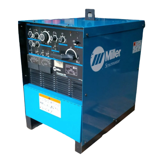
- Page 1 TM-353E January 2001 Eff. w/Serial Number JJ339876 Processes TIG (GTAW) Welding Stick (SMAW) Welding Description Arc Welding Power Source Syncrowave 250 60 Hz, 50 Hz Visit our website at www.MillerWelds.com...
-
Page 2: Table Of Contents
TABLE OF CONTENTS 1. Safety Precautions – Read Before Using ..........1.1 Symbol Usage . - Page 3 Declaration of Conformity For European Community (CE) Products NOTE This information is provided for units with CE certification (see rating label on unit.) Miller Electric Mfg. Co. Manufacturer’s Name: 1635 W. Spencer Street Manufacturer’s Address: Appleton, WI 54914 USA Syncrowave...
-
Page 5: Safety Precautions - Read Before Using
SECTION 1 – SAFETY PRECAUTIONS FOR SERVICING safety_stm1 4/95 1-1. Symbol Usage Y Marks a special safety message. Means Warning! Watch Out! There are possible hazards with this procedure! The possible hazards are shown in the adjoining symbols. Means NOTE; not safety related. This group of symbols means Warning! Watch Out! possible ELECTRIC SHOCK, MOVING PARTS, and HOT PARTS hazards. -
Page 6: Emf Information
FALLING EQUIPMENT cause MOVING PARTS can cause injury. serious personal injury and equipment 1. Keep away from moving parts. damage. 2. Keep away from pinch points such as drive rolls. 1. Use lifting eye to lift unit only, NOT running gear, OVERUSE can cause OVERHEATED gas cylinders, or any other accessories. -
Page 7: Section 2 - Definitions
SECTION 2 – DEFINITIONS 2-1. Warning Label Definitions Warning! Watch Out! There are possible hazards as shown by the symbols. Electric shock from welding electrode or wiring can kill. 1.1 Wear dry insulating gloves. Do not touch electrode with bare hand. Do not wear wet or damaged gloves. -
Page 8: Rating Label For Ce Products
2-2. Rating Label For CE Products ISO/IEC 974-1 7A/10.2V 310A/22.4V 100% 310A 200A 155A = 80V 22.4V 18V 16.2V 5A/20.2V 310A/32.4V 100% 310A 200A 155A = 80V 32.4V 28V 26.2V = 220 = 117.2A I = 59A 1max 1Eff 50 Hz = 380 = 72.2A I = 36A... -
Page 9: Symbols And Definitions
2-3. Symbols And Definitions NOTE Some symbols are found only on CE products. Gas Tungsten Arc Shielded Metal Arc Amperes Panel–Local Welding (GTAW) Welding (SMAW) Do Not Switch Volts Arc Force (DIG) Spot Timer While Welding Output Circuit Breaker Remote Temperature Protective Earth High Frequency -... -
Page 10: Section 3 - Installation
SECTION 3 – INSTALLATION 3-1. Specifications Amperes Input at AC Balanced Rated Load Output, 50/60 Hz, Single-Phase Rated 200 V 230 V 460 V 575 V PFC** Welding Output Range Rating NEMA Class II 11.4 (4.6*) (4*) (2*) (1.6*) (0.89*) (0.68*) (40) –... -
Page 11: Duty Cycle And Overheating
3-3. Duty Cycle And Overheating Duty Cycle is percentage of 10 min- utes that unit can weld at rated load without overheating. If unit overheats, thermostat opens, output stops, light goes on (CE models only), and cooling fan runs. Wait fifteen minutes for unit to cool. Reduce amperage or duty cycle be- fore welding. -
Page 12: Selecting A Location
3-4. Selecting A Location Lifting Eye Lifting Forks Use lifting eye or lifting forks to move unit. Movement If using lifting forks, extend forks beyond opposite side of unit. Rating Label (Non CE Models Only) Rating Label (CE Models Only, See Section 2-2) Use rating label to determine input power needs. -
Page 13: Tipping
3-6. Tipping Y Be careful when placing or moving unit over uneven surfaces. 3-7. Weld Output Terminals And Selecting Cable Sizes Y ARC WELDING can cause Electromagnetic Interference. To reduce possible interference, keep weld cables as short as possible, close together, and down low, such as on the floor. Locate welding operation 100 meters from any sensitive electronic equipment. -
Page 14: Remote 14 Receptacle
3-8. Remote 14 Receptacle Socket* Socket Information 24 volts ac. Contact closure to A completes 24 volts ac contactor control circuit. Command reference; 0 to +10 volts dc output to remote control. Remote control circuit common. C L N 0 to +10 volts dc input command signal from remote control. Chassis common. -
Page 15: 3-10.Electrical Service Guide
3-10. Electrical Service Guide NOTE All values calculated at 60% duty cycle. Without Power Factor 60 Hertz Models With Power Factor Correction Correction Input Voltage Input Amperes At Rated Output Max Recommended Standard Fuse Or Circuit Breaker Rating In Amperes Min Input Conductor Size In AWG/Kcmil Max Recommended Input Conductor Length (53) -
Page 16: 3-11.Placing Jumper Links And Connecting Input Power
3-11. Placing Jumper Links And Connecting Input Power Check input voltage available at site. Jumper Link Label Check label inside your unit– 200 VOLTS 230 VOLTS 460 VOLTS only one label is on unit. Y Only make connections for the voltages shown on the la- bel inside your unit. -
Page 17: Section 4 - Operation
SECTION 4 – OPERATION 4-1. Controls Ammeter See Section 4-3. Voltmeter See Section 4-3. High Frequency Switch See Section 4-11. Output (Contactor) Switch See Section 4-8. Spot Time Switch And Control (Optional) See Section 4-5. Preflow Time Control (Optional) See Section 4-12. AC Balance Control See Section 4-6. -
Page 18: Output Selector Switch
4-2. Output Selector Switch Output Selector Switch Y Do not use AC output in damp areas, if movement is confined, or if there is dan- ger of falling. Use AC output ONLY if required for the welding process, and then use a remote control. -
Page 19: Crater Time Controls
4-4. Crater Time Controls Crater Time Control Use control to reduce current over a set period of time (0–15 seconds) at the end of the weld cycle when NOT using a remote current control. Crater Time Switch ON – provides crater time. OFF –... -
Page 20: Ac Balance Control
4-6. AC Balance Control AC Balance Control Balance Control (AC GTAW): Control changes the AC output square wave. Rotating the control towards 10 provides deeper pene- tration. Rotating the control towards 0 provides more cleaning action of the workpiece. When the control is in the Balanced position, the wave shape provides equal penetration and cleaning action. -
Page 21: Amperage Adjustment Controls
4-7. Amperage Adjustment Controls Amperage Adjustment Control Use control to adjust amperage, and preset amperage on ammeter (see Section 4-3). This control may be adjusted while welding. For remote amperage control, front panel control setting is the maximum amperage available. For example: If front panel control is set to 200 A, the range of the remote amperage control is 5 to 200 A. -
Page 22: Arc Controls
4-9. Arc Controls Arc Control (Dig) For AC And DC SMAW Welding When set at 0, short-circuit amper- age at low arc voltage is the same as normal welding amperage. When setting is increased, short- circuit amperage at low arc voltage increases. -
Page 23: 4-11.High Frequency Controls
4-11. High Frequency Controls Y Place High Frequency switch in Off position before using the shielded metal arc welding (SMAW) process. High Frequency Switch START – (Up position) provides HF for arc starting only. High frequency turns on to help start arc when out- put is enabled. -
Page 24: Section 5 - Theory Of Operation
SECTION 5 – THEORY OF OPERATION Input Terminal Board TE1 Provides means for operation on Background Input Power Main different input voltages. Power Terminal Switch Transformer Source Power Switch S1 Board TE1 1-Phase Provide on/off control of unit. Line Input 115 VAC Fan Motor FM Power... - Page 25 15 115 Volts AC Duplex Recep- tacle RC2 Provides connection point for auxil- iary equipment. Hall Device Work Weld 16 Postflow Timer TD1 Output Stabilizer Terminal Controls shielding gas and coolant postflow time. Voltmeter 17 Gas Valve GS1 Output Selector Provides shielding gas during the Switch weld cycle.
-
Page 26: Section 6 - Troubleshooting
SECTION 6 – TROUBLESHOOTING 6-1. Troubleshooting Table See Section 6-2 for test points and values and Section 10 for parts location. Use MILLER Testing Booklet (Part No. 150 853) when servicing this unit. Trouble Remedy Prior to Serial No. KG164875, no weld Be sure line disconnect switch is in the On position. - Page 27 Trouble Remedy Check SCRs in main rectifier SR1, and replace if necessary. If any SCRs are replaced, Check capac- itors C7 through C10 for a short or open, and check for proper connections. Replace C7 through C10 if necessary. Check control board PC1 and connections, and replace if necessary. Check connections to line filter FL1.
- Page 28 Trouble Remedy No high frequency at spark gaps G. Check position of High Frequency switch S2 (see Section 4-11). Place Output (Contactor) switch S3 in Remote position and be sure remote control is connected to Remote receptacle RC1 (see Section 3-8). Check circuit breaker CB1, and reset if open (see Section 7-2).
- Page 29 Trouble Remedy Check Control relay CR2 contacts 4 and 7 for proper operation. Replace CR2 if necessary. Check coil voltage and connections of gas valve GS1. Check continuity of coils. Replace GS1 if nec- essary. No power output at 115 volts ac recep- Check circuit breaker CB1, and reset if open (see Section 7-2).
-
Page 30: Troubleshooting Circuit Diagram For Welding Power Source
6-2. Troubleshooting Circuit Diagram For Welding Power Source Y Disable high frequency by placing High Frequency switch S2 in Off position before testing unit. Link 1 Link 2 TD1 begins to time out when CR5 deenergizes TD3 begins to time out when CR4 energizes CR2 energizes when remote contactor... - Page 31 Test Equipment Needed: Voltage Readings Tolerance – 10% unless specified Reference – circuit common (lead 42) unless noted See Figure 10-1 for No calibration available HD1 location for voltmeter V1 Wiring Diagram – Section 10 230 volts ac 77 volts ac 82.5 volts ac 57 volts ac V5, V6...
-
Page 32: Waveforms For Section 6-2
6-3. Waveforms For Section 6-2 Waveforms shown are for 60 Hertz models; waveforms for 50 Hertz models are similar. 5 ms 1 V 5 ms 50 V A. SR1 Gate Pulse With Respect To Cathode B. DC Open-Circuit Voltage With Amperage At No Load Adjustment Control At Maximum 5 ms 20 V... - Page 33 5 ms 50 V E. AC Output, 100 Amperes, 24 Volts AC (Re- sistive Load) Test Equipment Needed: Syncrowave 250 TM-353 Page 29...
-
Page 34: Control Board Pc1 Testing Information (Use With Section 6-5)
6-4. Control Board PC1 Testing Information (Use With Section 6-5) Y Disable high frequency by placing High Frequency switch S2 in Off position before testing unit. Be sure plugs are secure before testing. See Section 6-5 for specific values during testing. Control Board PC1 Receptacle RC51 Receptacle RC52... -
Page 35: Control Board Pc1 Test Point Values
6-5. Control Board PC1 Test Point Values a) Tolerance – unless specified PC1 Voltage Readings b) Reference – to circuit common (lead 42) unless noted Receptacle Value RC51 18 volts ac input 18 volts ac input +10 volts dc output Circuit common Not used Not used... - Page 36 Receptacle Value RC55 Circuit common +1.65 volts dc per 100 amperes of weld output with respect to pin 1 –15 volts dc output 0 to +4 volts dc input from min. to max. of Arc Control R2 with Arc Control switch S6 On 10 volts ac input for synchronization +5.8 volts dc output –15 volts dc input from Max.
-
Page 37: Remote Board Pc2 Testing Information (Use With Section 6-7)
6-6. Remote Board PC2 Testing Information (Use With Section 6-7) Y Disable high frequency by placing High Frequency switch S2 in Off position before testing unit. Be sure plugs are secure before testing. See Section 6-7 for specific values during testing. Remote 14 Filter Board PC2 Remote 14 receptacle RC1 See Section 3-8 for information. -
Page 38: Remote 14 Filter Board Pc2 Test Point Values (Use With Section 6-2 And Section 6-6)
6-7. Remote 14 Filter Board PC2 Test Point Values (Use With Section 6-2 And Section 6-6) a) Tolerance – unless specified PC2 Voltage Readings b) Reference – to circuit common (lead 42) unless noted Receptacle Value 24 volts ac Contact closure to A completes 24 volts ac contactor control circuit Command reference;... -
Page 39: Meter Calibration
6-8. Meter Calibration Be sure plugs are secure before calibrating meter. Control Board PC1 Voltmeter V1 No calibration available for ammeter Ammeter A1 offset, or for voltmeter V1. Top View Amperes Adjust R19 for amperage gain to match external calibrated meter using load bank set at desired load. -
Page 40: Input Voltage Labels And Connections
6-9. Input Voltage Labels And Connections Input Voltage Label And Con- nection Diagram – Only One Label Is On Unit Terminal Strip TE1 Test Equipment Needed: ST-154 793-A / ST-114 947-A / ST-121 000-A / ST-131 735 TM-353 Page 36 Syncrowave 250... -
Page 41: Section 7 - Maintenance
SECTION 7 – MAINTENANCE 7-1. Routine Maintenance Y Disconnect power before maintaining. 3 Months Clean And Repair Or Replace Tighten Replace Unreadable Weld Cracked Labels Terminals Weld Cables Adjust Spark Replace Gaps Cracked Parts Torch Cable 14-Pin Cord Gas Hose 6 Months Blow Out Or Vacuum Inside,... -
Page 42: Fuses F1 And F2
7-3. Fuses F1 And F2 Fuse F1 (See Parts List For Rating) Fuse F1 (between leads 50 and 150) protects wiring harness from shorted SR2. If F1 opens, you may experience problems with arc start- ing and arc performance in the DC TIG mode. -
Page 43: Section 8 - High Frequency (Hf)
SECTION 8 – HIGH FREQUENCY (HF) 8-1. Welding Processes Using HF HF Voltage GTAW – helps arc jump air gap between torch and workpiece and/ or stabilize the arc. SAW – helps arc reach workpiece through flux granules. Flux Work Work Gas Tungsten Arc Submerged Arc... -
Page 44: Correct Installation
8-3. Correct Installation Weld Zone 50 ft (15 m) 50 ft (15 m) Ground All Metal Objects And All Wiring In Welding Zone Using #12 AWG Ground Wire Workpiece If Required By Codes Nonmetal Building Metal Building Ref. S-0695 / Ref. S-0695 HF Source (Welder With Built-In HF Or Electrically join (bond) all conduit sections Metal Building Panel Bonding Methods... -
Page 45: Section 9 - Electrical Diagrams
SECTION 9 – ELECTRICAL DIAGRAMS The circuits in this manual can be used for troubleshooting, but there might be minor circuit differences from your machine. Use circuit inside machine case or contact distributor for more information. The following is a list of all diagrams for models covered by this manual. Model Serial Or Style Number Circuit Diagram... - Page 46 SC-114 914 Figure 9-1. Circuit Diagram For Syncrowave 250 Effective With Serial No. JJ339876 Thru JJ351864 TM-353 Page 42 Syncrowave 250...
- Page 47 SC-120 877 Figure 9-2. Circuit Diagram For Syncrowave 250 Effective With Serial No. JJ351865 Thru JJ365633 Syncrowave 250 TM-353 Page 43...
- Page 48 SC-121 280 Figure 9-3. Circuit Diagram For Syncrowave 250 Effective With Serial No. JJ365634 Thru JJ503983 TM-353 Page 44 Syncrowave 250...
- Page 49 SC-124 314 Figure 9-4. Circuit Diagram For Syncrowave 250 Effective With Serial No. JJ503984 Thru JK572897 Syncrowave 250 TM-353 Page 45...
- Page 50 SC-124 785-B Figure 9-5. Circuit Diagram For Syncrowave 250 Effective With Serial No. JK572898 Thru JK690986 TM-353 Page 46 Syncrowave 250...
- Page 51 SC-132 697-A Figure 9-6. Circuit Diagram For Syncrowave 250 Effective With Serial No. JK690987 Thru KA806712 Syncrowave 250 TM-353 Page 47...
- Page 52 SC-137 431 Figure 9-7. Circuit Diagram For Syncrowave 250 Effective With Serial No. KA806713 Thru KA877024 TM-353 Page 48 Syncrowave 250...
- Page 53 SC-135 581 Figure 9-8. Circuit Diagram For Syncrowave 250 Effective With Serial No. KA877025 Thru KB010829 Syncrowave 250 TM-353 Page 49...
- Page 54 SC-142 524 Figure 9-9. Circuit Diagram For Syncrowave 250 Effective With Serial No. KB010830 Thru KB110694 TM-353 Page 50 Syncrowave 250...
- Page 55 SC-148 144 Figure 9-10. Circuit Diagram For Syncrowave 250 Effective With Serial No. KB110695 Thru KC252675 Syncrowave 250 TM-353 Page 51...
- Page 56 SC-154 649-C Figure 9-11. Circuit Diagram For Syncrowave 250 Effective With Serial No. KC252676 Thru KG029204 TM-353 Page 52 Syncrowave 250...
- Page 57 SC-178 835 Figure 9-12. Circuit Diagram For Syncrowave 250 Effective With Serial No. KG029205 Thru KG062109 Syncrowave 250 TM-353 Page 53...
- Page 58 SC-179 303-A Figure 9-13. Circuit Diagram For Syncrowave 250 Effective With Serial No. KG062110 Thru KG170300 TM-353 Page 54 Syncrowave 250...
- Page 59 SC-181 109-E Figure 9-14. Circuit Diagram For Syncrowave 250 Effective With Serial No. KG170301 Thru KH526230 Syncrowave 250 TM-353 Page 55...
- Page 60 SC-188 161-A Figure 9-15. Circuit Diagram For Syncrowave 250 Effective With Serial No. KH526231 And Following TM-353 Page 56 Syncrowave 250...
- Page 61 Notes Syncrowave 250 TM-353 Page 57...
- Page 62 Figure 9-16. Wiring Diagram For Syncrowave 250 Effective With Serial No. KH526231 And Following TM-353 Page 58 Syncrowave 250...
- Page 63 SD-188 162-A Syncrowave 250 TM-353 Page 59...
- Page 64 Figure 9-17. Circuit Diagram For Control Board PC1 Effective With Serial No. KH508255 And Following (Part 1 Of 2) TM-353 Page 60 Syncrowave 250...
- Page 65 SD-187 644 (1 of 2) Syncrowave 250 TM-353 Page 61...
- Page 66 Figure 9-18. Circuit Diagram For Control Board PC1 Effective With Serial No. KH508255 And Following (Part 2 Of 2) TM-353 Page 62 Syncrowave 250...
- Page 67 SD-187 644 (2 of 2) Syncrowave 250 TM-353 Page 63...
- Page 68 SA-121 282 Figure 9-19. Circuit Diagram For RFC Board PC2 Effective With Serial No. JJ365634 Thru KB010829 SA-158 763 Figure 9-20. Circuit Diagram For Remote 14 Filter Board PC2 Effective With Serial No. KF959379 And Following SA-120 872 Figure 9-21. Circuit Diagram For Optional Snubber Board PC3 Effective With Serial No.
- Page 69 SA-044 725-C Figure 9-23. Circuit Diagram For Postflow Timer Board TD1 Effective With Serial No. JJ339876 And Following SA-045 288-D Figure 9-22. Circuit Diagram For Optional Preflow Timer Board TD3 Effective With Serial No. JJ339876 And Following Syncrowave 250 TM-353 Page 65...
- Page 70 Notes TM-353 Page 66 Syncrowave 250...
- Page 71 TM-353E January 2001 Eff. w/Serial Number JJ339876 Processes TIG (GTAW) Welding Stick (SMAW) Welding Description Arc Welding Power Source Syncrowave 250 60 Hz, 50 Hz Visit our website at www.MillerWelds.com...
-
Page 72: Section 10 - Parts List
SECTION 10 – PARTS LIST Hardware is common and ST-120 135-R Figure 10-1. Main Assembly not available unless listed. TM-353 Page 68 Syncrowave 250... - Page 73 Item Dia. Part Description Quantity Mkgs. Figure 10-1. Main Assembly ... . . 114 741 COVER, top (Prior to KG170301) ........
- Page 74 Item Dia. Part Description Quantity Mkgs. Figure 10-1. Main Assembly (Continued) ... . 114 755 BASE, (Prior to KE727074) ..........
- Page 75 Includes Item 26 Figure 10-6 ST-120 088-G Figure 10-2. Panel, Front w/Components Item Dia. Part Description Quantity Mkgs. Figure 10-2. Panel, Front w/Components (Fig 10-1 Item 29) ....097 922 KNOB, pointer .
- Page 76 Item Dia. Part Description Quantity Mkgs. Figure 10-2. Panel, Front w/ Components (Continued) ....044 723 ..CIRCUIT CARD, postflow ........
- Page 77 Item Dia. Part Description Quantity Mkgs. Figure 10-3. Rectifier, Si Diode (Fig 10-1 Item 2) ..C7-10 031 689 CAPACITOR, rectifier ..........
- Page 78 Item Dia. Part Description Quantity Mkgs. Figure 10-5. Panel, Mtg Components (Fig 10-1 Item 7) ..186 468 RESISTOR, WW fxd 100W 50 ohm ....... . .
- Page 79 ST-120 003-P Figure 10-6. Control Panel, Lower Front Item Dia. Part Description Quantity Mkgs. Figure 10-6. Control Panel, Lower Front (Fig 10-2 Item 18) ....116 477 CONTROL PANEL, lower (Prior to JK572898) .
- Page 80 Item Dia. Part Description Quantity Mkgs. Figure 10-6. Control Panel, Lower Front (Continued) ....126 750 CAPACITOR ASSEMBLY, (Eff w/JK537589 thru JK690986) ... .
- Page 81 Item Dia. Part Description Quantity Mkgs. Figure 10-6. Control Panel, Lower Front (Fig 10-2 Item 18) (Continued) ... . . 115 967 COIL, HF coupling (Prior to JK572898) ......
- Page 82 Eff w/KE558763 the Water Valve Option (042 138) is no longer available and all other options are available as Field Options only. Dia. Part Description Quantity Mkgs. Optional Equipment ..... . 042 138 WATER VALVE, (consisting of) .
- Page 84 1635 West Spencer Street Appleton, WI 54914 USA International Headquarters–USA Phone: 920-735-4505 USA & Canada FAX: 920-735-4134 International FAX: 920-735-4125 European Headquarters – United Kingdom Phone: 44 (0) 1204-593493 FAX: 44 (0) 1204-598066 PRINTED IN USA 1998 Miller Electric Mfg. Co.