Table of Contents
Advertisement
User Manual
E
C
O
R
2
E
C
O
R
2
E
C
O
E
C
O
(
8
/
4
-
c
h
a
(
8
/
4
-
c
h
a
E
C
O
E
C
O
(
8
/
4
-
c
h
a
(
8
/
4
-
c
h
a
6
4
D
i
g
i
t
6
4
D
i
g
i
t
R
2
6
4
-
8
R
2
6
4
-
8
n
n
e
l
D
V
R
E
C
n
n
e
l
D
V
R
E
C
R
2
6
4
-
8
R
2
6
4
-
8
n
n
e
l
D
V
R
E
C
n
n
e
l
D
V
R
E
C
a
l
V
i
d
e
o
a
l
V
i
d
e
o
/
4
F
2
/
4
F
2
O
R
2
6
4
w
i
t
h
o
O
R
2
6
4
w
i
t
h
o
/
4
D
2
/
4
D
2
O
R
2
6
4
w
i
t
h
O
R
2
6
4
w
i
t
h
R
e
c
o
r
d
R
e
c
o
r
d
u
t
D
V
D
+
R
W
)
u
t
D
V
D
+
R
W
)
D
V
D
+
R
W
)
D
V
D
+
R
W
)
e
r
e
r
Advertisement
Table of Contents

Related Manuals for EverFocus ECOR 264-8/4 F2


Summary of Contents for EverFocus ECOR 264-8/4 F2
- Page 1 User Manual...
- Page 2 All rights reserved. No part of the contents of this manual may be reproduced or transmitted in any form or by any means without written permission of the Everfocus Electronics Corporation. Release Date: September 2010 QuickTime is a registered trademark of the Apple Computer, Inc.
-
Page 3: Safety Precautions
This Product is RoHS compliant. Ihr EverFocus Produkt wurde entwickelt und hergestellt mit qualitativ Your EverFocus product is designed and manufactured with high hochwertigen Materialien und Komponenten, die recycelt und wieder quality materials and components which can be recycled and reused. -
Page 4: Table Of Contents
TABLE OF CONTENTS PRODUCT OVERVIEW ........................1 1.1 F ................................1 EATURES 1.2 P ............................2 ACKAGE CONTENTS 1.3 S ..............................3 PECIFICATIONS 1.4 F ..............................5 RONT PANEL 1.5 R ............................... 7 EAR PANEL 1.6 V ........................8 IDEO INPUT OUTPUT INSTALLATION 1.6.1 Video inputs ................................ - Page 5 3.4 P ................................ 22 LAYBACK 3.5 PTZ ................................. 24 3.5.1 General PTZ control (if PTZ cameras are installed) ....................24 3.5.2 Express Control of PTZ ............................25 3.6 L ................................26 AYOUT 3.6.1 Bring a camera to full screen mode ........................26 3.7 C ............................
- Page 6 LAYBACK 6.6 R ........................... 105 EMOTE CONTROL EVERFOCUS DDNS SETUP ......................107 TROUBLESHOOTING ........................109 APPENDIX A: TIMING OF ALARM MODES .................... 110 APPENDIX B: EXPRESS SETUP RECORDING VALUE SELECTION RULES ........113 APPENDIX C: REMOTE CONTROL ......................115 APPENDIX D: MOBILE PHONE BROWSER VIEW ................. 116...
-
Page 7: Product Overview
PowerCon 4.x software watchdog function with notification options optional RS-485 remote control (EKB 500) free EverFocus DDNS service: DDNS account registration directly from DVR setup... -
Page 8: Package Contents
1.2 P ACKAGE CONTENTS - Digital Video Recorder x1 - User Manual x 1 - AC Adapter x 1 - Mouse x 1 - Terminal Block x 6 - IR Remote Control x 1 - Battery x 2 - HDD Fixing Bracket x 1 set - Power Cord x 1 - SATA cable x 1 - Screws x 4 for HDD... -
Page 9: Specifications
1.3 S PECIFICATIONS ECOR 264-4F2 ECOR 264-8F2 ECOR 264-4D2 ECOR 264-8D2 Video format PAL / CCIR Display format main monitor 1, 4x multiscreen, PiP 1, 4, 6, 8, 9x multiscreen, PiP 4 inputs 1 Vp-p composite PAL, BNC, 8 inputs 1Vp-p composite PAL, BNC, Video input automatic 75 Ohm termination automatic 75 Ohm termination... - Page 10 12 V DC, via included power supply 100 ~ 240 V AC Power consumption 40 W max. Ambient temperature 0°C ~ +40°C Dimensions (WxHxD) 320 x 54,3 x 208,9 mm Weight 4,0 kg (w/o HDD) Supported PTZ Protocols EverFocus, Pelco D, Pelco P, Samsung Electr., Transparent...
-
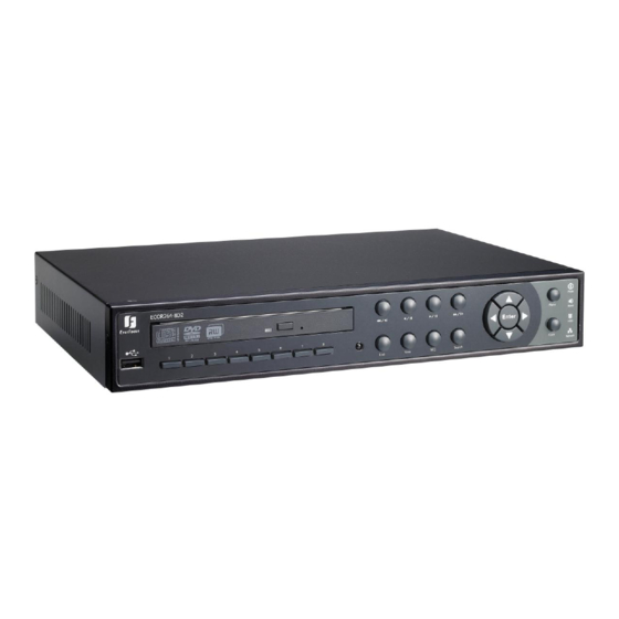
Page 11: Front Panel
1.4 F RONT PANEL Your primary interaction with your new DVR will be through the Front Panel buttons and their corresponding buttons on the included IR Remote Control. Take a moment to learn where the keys are as the remainder of the manual will refer to them often. Figure 1-1 Front Panel IR Receiver: Receiver for IR remote control... - Page 12 Menu: Press this key to enter/exit MAIN SETUP MENU. Live: Press this key to show live view. Press to exit from playback mode. View: Press this key to switch between 4x, PiP (Picture In Picture), full screen and 9x. Note: PIP display is not available in playback mode. Note: This key is also used for BNC and VGA selection at the initial setup.
-
Page 13: Rear Panel
1.5 R EAR PANEL During initial setup you will be connecting your DVR to multiple input and output devices. This is done through the rear panel. Figure 1-2 Rear Panel 1 Video in Connect camera’s video output or other composite video source to the video input connection. -
Page 14: Video Input / Output Installation
1.6 V IDEO INPUT OUTPUT INSTALLATION Cameras and CCTV monitors must use copper center conductor/copper braid 75 Ohm video cable (e.g. RG-59, RG-6, RG-11) with BNC connectors. To avoid impedance mismatch and undesired loss/reflections, 50 Ohm coax cable (e.g. RG-58), or 75 ohm foil shield antenna cable and other types of coaxial cable are not compatible. -
Page 15: Alarm Contact Installation
1.7 A LARM CONTACT INSTALLATION The alarm input can be used to start recording or for recording rate adjustment. In addition, alarm reactions such as camera display on the monitor, buzzer, e-mail and network alarm are available. The alarm output relay can be switched if required. -
Page 16: Keyboard / Ptz Installation
Cable length from box to device („Stubs“) has to be limited to 2m using connector boxes. RS-485 bus serial wiring with connector boxes and connection cable Direct RS-485 bus star wiring is not supported unless using an EverFocus Model EDA997A (see below). Improper RS-485 bus star wiring An EDA997A RS-485 signal distributor may be used to use a star wiring configuration. -
Page 17: Socket Pin Assignment
A RS-485 distributor can also be used to increase the maximum number of devices on the bus as well as the total range. Each distributor output provides another RS-485 bus. This allows each output to extend an additional 1200m, and it also enables the additional connection of 31 further devices to each output (the output itself represents one device). -
Page 18: Speed Dome Installation
PowerCon software if the DVR is connected to a network. Local telemetry control is provided by USB - mouse control or by the optional EKB-500 keyboard. Supported protocols: EverFocus, Pelco-D, Pelco-P, Samsung, Transparent Required DVR settings: RS-485 receiver address in CAMERA menu (Section 4.3) RS-485 parameters and protocol in the I/O CONTROL menu (Section 4.10.4) -
Page 19: Network Connection
1.10 N ETWORK CONNECTION This section only describes physical connection to an Ethernet network. This step must be completed before the DVR can connect to the network. There are two basic types of connection: 1.10.1 Direct PC Connection through Crossover Network Cable The point-to-point connection of DVR and PC requires a crossover (crossed) network cable. -
Page 20: Final Install Process
Figure 1-4 Network Connection through Patch Cable Pinout of straight patch cable 1.11 F INAL NSTALL ROCESS Once you have completed the basic wiring connections, you are ready to turn on the DVR. Simply plug in the power source. The POWER LED will light up if power is normal. Once the system has finished loading, you can begin to set up the menu options for the DVR. -
Page 21: Mouse And Front Panel Operation
Chapter 2 MOUSE AND FRONT PANEL OPERATION ECOR 264 F2/D2 DVRs support multiple sources to control the DVR. It can be controlled with a mouse, the front panel, an EKB 500 (optional), and the handheld IR remote control. This chapter will cover the basic operation using the mouse and the front panel buttons. 2.1 G USB M ENERAL... -
Page 22: Operation In The Configuration Menu
2.1.3 Operation in the Configuration Menu Click on the icon to access the Configuration Menu. The Configuration menu screens (shown in Figure 2-2 OSD Menu) are divided into 3 main sections. Figure 2-2 OSD Menu 1. In section 1, there are ten setup options available. Move the mouse over an icon and click to select it. 2. - Page 23 Bar: Click and hold on the bar to adjust the set point Left or Right. * Note about on-screen keyboard: Click on a button to input that character. The buttons on the right and bottom have the following functions: Space Enter a space Caps Switch to capital letters...
-
Page 24: General Front Panel Operation
2.2 G ENERAL RONT ANEL PERATION 2.2.1 How to select a channel 1. In a view consisting of more than one channel, press the arrow keys (Up/Down/Right/Left) to scroll through each channel that is displayed. The selected channel will be highlighted by white frame. Pressing the “left”... -
Page 25: Field Input Options
Figure 2-3 OSD Menu 1. In section 1, there are ten setup options available. Use arrow keys to highlight an icon and press “Enter” to select it. 2. In section 2, the main choices for the selected icon will be displayed. Use Up/Down arrow keys to highlight a choice and press “Enter”... - Page 26 * Note about on-screen keyboard: Use the arrow buttons to highlight each character and press the “Enter” key on the front panel to input the selected characters. When finished, highlight “Done” and press the “Enter” key on the front panel to confirm.
-
Page 27: General Dvr Operations
Chapter 3 GENERAL DVR OPERATIONS This chapter introduces the operations on major functions including playback, layout change, sequence, triplex operations, copy, and search. 3.1 R ECORD By default, the DVR will always be in record mode. When the DVR is turned on, it will start to record. The exceptions are: 1. -
Page 28: Select Camera Operation
(If you operate the device via front panel: Press the ENTER key to open the dropdown box. Use the up/down arrow keys to highlight the desired name and press the ENTER key to confirm your selection). + To input password by mouse: click the password field to bring up the on-screen keyboard (see Figure 3-2 On-screen Keyboard). - Page 29 The playback bar will show (see figure below): 1 2 3 4 10 11 13 12 10 10 5 6 7 8 2009/05/25 09:09:30PM 2009/05/25 09:09:40PM 2009/05/25 09:10:30PM 1. Stop key: press to stop playback 2. Slow Reverse key: press to start slow reverse playback 3.
-
Page 30: Ptz
Click “Delete” button 9. For Auto Pan a. Click “Auto Pan” button 10. Pattern Operation (Pattern is the “0” Tour in Everfocus and Pelco PTZ cameras) a. Click “Pattern” button 11. Steps to run a tour a. Click “Tour” button b. -
Page 31: Express Control Of Ptz
REMEMBER: Click “X” at the top-right corner to hide the PTZ menu (see Express control below) Click “Exit” to leave PTZ function. “X” only HIDES the PTZ control panel. “EXIT” closes the panel and exits PTZ mode!! Other controls will not respond until you EXIT the PTZ mode!! 3.5.2 Express Control of PTZ... -
Page 32: Layout
3.6 L AYOUT The ECOR 264 F2/D2 DVR has several display modes available, depending on the number of cameras the DVR supports. The different available layouts for a 8 camera model are shown below: NOTE: PIP display is not available in Playback mode The first three layouts are available on all models;... -
Page 33: Display
3.8 D ISPLAY Press the Display button on the menu by using the mouse or selecting this icon with the front panel keys and pressing ‘Enter’. Pressing/clicking cycles through the four OSD formats: 1. Press to show camera information. Please see the following table for camera information icons. Recording Playback Fast forward... -
Page 34: Search
4. When in ZOOM mode, the mouse cursor will change to a different icon in different areas of the screen. Or, use the arrow keys to bring a different portion of the magnified image into view. Users can control the portion of the magnified image to be displayed by clicking directly on screen: Figure 3-4 Zoom Express Control The screen is divided into a 4x4 grid. -
Page 35: Time Search
3.11.1 Time Search Figure 3-5 Search Menu – Time Search Play From: Select the time to begin the search by choosing the Date and Time. Click on the “Play” button to start the search. The DVR will automatically begin to play the video selected. The DVR will play the nearest time if there is no data at the selected time. -
Page 36: Smart Search
From: Select starting date and time To: Select ending date and time. Camera: Select which cameras to include in the search. Event: Select which event type(s) to search for. Choose from Alarm, Motion or Video Loss. Click on the “Search” button to start searching. The search results will be shown as a list of events. Prev Page: Go to previous page Next Page: Go to next page Play: Playback selected item... - Page 37 Figure 3-7 Search Menu – Smart Search From: Select starting date and time. To: Select end date and time. Camera: Select which cameras to review. Grid Setting: Press Grid Setting button to open the motion grid setup window. Select the area to be reviewed. The smart search zones have to be activated in the “Motion” settings within the camera setting menu.
-
Page 38: Snapshot Search
How to select motion grid by mouse: 1. Select the grid square in the upper-left of the desired rectangle. 2. Select the grid square in the lower-right of the desired rectangle. 3. The area between upper-left and lower-right grid will be selected. How to select motion grid by front panel: 1. -
Page 39: Copy
Result Type: Thumbnail is used as result type. Search Date: Select search date and time Search Direction: Select search direction, either forward or backward. Search Camera: Select which camera to be searched. Result Interval: Select interval of the snapshot to be searched. Available from 1 min, 5 min, 10 min, 30 min, 1 hour, 2 hour, 4 hour, 12 hour and 1 day. -
Page 40: Logout
Figure 3-9 Copy Menu Camera: Select which cameras will be archived. Choose “Select All” to select all the cameras. Player: Check the box to include the ePlayer program as part of the copy (recommended). Start Date/Time: Select the starting date/time to be archived. End Date/Time: Select the ending date/time to be archived. -
Page 41: Dvr Configuration
Chapter 4 DVR CONFIGURATION This chapter will walk you through the DVR Menu Settings step by step and show you how to set the DVR for your specific application. 4.1 C ONFIGURATION 1. To bring up the Main Menu, press the “Menu” key on the front panel or right-click with the USB mouse to bring up the OSD menu bar. - Page 42 Time: Sets the current time of DVR. Record Mode: Choose from Normal+Event: Normal recording plus event recording. Event Only: Event recording only. Schedule Rec: Schedule recording. For Event recording, enter the estimated number of hours per day for event recording. Resolution: Select recording resolution based on video format.
- Page 43 PPPoE: This is for direct DSL connection application ONLY (no router). Check with your ISP to see if they use PPPoE. IP Address: This field shows the current IP Address for the DVR. If Fixed IP address is used then this value must be set manually.
-
Page 44: Camera Setting
4.3 C AMERA ETTING Figure 4-2 is a screenshot of the CAMERA SETTING MENU. This menu is used to configure individual camera settings. Figure 4-2 Camera Menu-Basic Setting 4.3.1 Basic Setting Camera: Select the camera to be configured. Title: The title setting allows you to assign a title to the selected camera. Each title supports up to 16 characters. - Page 45 Normal Speed: Recording speed for continuous recording. The speed is limited by the maximum total recording capacity of the DVR (displayed in the lower left corner) as allocated across all the installed cameras. Changing the resolution will also effect the value (fps) which is displayed next to the field showing the remaining image rate for all cameras.
-
Page 46: Video Adjust
4.3.2 Video Adjust Figure 4-3 Camera Menu – Video Adjust Camera: Select the camera you wish to adjust. “Title” will change to the name of the selected camera. Brightness: Adjusts how bright/dark the picture appears. If details appear to be lost in the shadows or darker regions, try increasing the Brightness. -
Page 47: Motion
4.3.3 Motion Figure 4-4 Camera Menu – Motion Camera: Select the camera you wish to configure. “Title” will change to the title name of the selected camera. Enable: Check box to enable motion detection. Other motion options will not be available unless this feature is selected. - Page 48 Permanent: Alarm will remain on until the user presses the “Enter” key on front panel or otherwise resets the alarm condition. Transparent: Alarm output will remain switched as long as the event lasts. Trans+Timeout: Alarm output will remain switched until end of event plus indicated time. Timeout Duration: Time duration selectable from 1 to 150 seconds.
- Page 49 Figure 4-5 Camera Menu – Motion Grid Setting Apply To: This button can be used to copy the motion settings to other cameras. Select which cameras you wish to copy to. "Select All" selects all cameras, “Unselect All” deselects all cameras. Click “OK” to copy the settings or "Cancel"...
-
Page 50: Video Loss
4.3.4 Video Loss Figure 4-6 Camera Menu – Video Loss Camera: Select the camera you wish to configure, “Title” will change to the title name of the selected camera. Enable: Check box to enable Video Loss detection. Log: Check box to record video loss events in the log. Pre-alarm Record: Check box to start copying recorded video to the hard disk from 5 seconds before the video loss. -
Page 51: Record & Play Setting
Apply To: This button can be used to copy the video loss settings to other cameras. Select which cameras you wish to copy to. "Select All" selects all cameras, “Unselect All” deselects all cameras. Click “OK” to copy the settings or "Cancel" to exit without copying. 4.4 R &... -
Page 52: Built-In Calculator
mode. When schedule recording is disabled, as the default the DVR will automatically begin recording when it is first turned on. Time Stamp: Select if the time and date will display while recording. Choose the location for the time display from Top, Bottom or Off. Record Status Relay Output: Select from “NONE”... -
Page 53: Play
4.4.3 Play Figure 4-9 Record & Play Menu - Play Quick Playback: Check the box to enable the Quick Playback function as described below. Playback From X Seconds ago: When the DVR is put into playback (press PLAY), it will begin playing from the selected time. -
Page 54: Alarm & Event Setting
4.5 A & E LARM VENT ETTING Figure 4-10 is a screenshot of the ALARM & EVENT SETTING MENU. This menu will guide you through alarm and event setup. Figure 4-10 Alarm & Event Menu - Alarm 4.5.1 Alarm Alarm: Select the alarm input trigger connection number from 1 to 4 (or 8 – one trigger per camera input). Enable: Check box to enable response to that alarm trigger. - Page 55 Network Alarm: Check this box to send out a network alarm to a client PC when motion occurs. (This feature requires PowerCon software on the client PC and proper settings for the Alarm Server in the Network Setup menu; see Section 4.6.4 Alarm Server for more information) Active Camera: This field is for associating an alarm trigger with a specific camera.
-
Page 56: Event
4.5.2 Event This section covers notifications due to internal system event warnings. Figure 4-11 Alarm & Event Menu – Event Event: Select from the following event types. HD Temperature: Hard drive is over the safety warning temperature. HD Failure: If DVR fails to detect the HDD on start up, the system will create an HD failure event. HD Full: If the DVR is not set to Overwrite in the Record Menu, an event will be created when the HDD is filled. - Page 57 HD Temperature: Figure 4-12 Alarm & Event Menu – Event - HD Temperature Log: Check box to record HDD temperature events in the log. Buzzer: Check box to enable buzzer when hard drive’s temperature is over the “Temp. Warning Limit”. Email Notify: Check box to enable email notification when HDD temperature is over the “Temp.
- Page 58 HD Failure: Figure 4-13 Alarm & Event Menu – Event - HD Failure Log: Check box to record events in the log. Buzzer: Check box to enable the buzzer if no hard drive is detected on system startup. Email Notify: Check box to enable email notification function when HD fails. Email operation requires that valid email settings have been entered in the Network Setting/Email setup screen.
- Page 59 HD Full: Figure 4-14 Alarm & Event Menu – Event - HD Full Log: Check box to record events in the log. Buzzer: Check box to enable the buzzer when hard drive is full (recommended if the Record Overwrite function is disabled. See Section 5.4.1). Email Notify: Check box to enable email notification when HD is full.
- Page 60 HD Off: Figure 4-15 Alarm & Event Menu – Event - HD Off Buzzer: Check box to enable buzzer if the hard drive is turned off (disconnected) or becomes disabled (cannot be detected by the system). Email Notify: Check box to enable email notification when HD is off. Email operation requires that valid email settings have been entered in the Network Setting/Email setup screen.
- Page 61 Power Loss: Figure 4-16 Alarm & Event Menu – Event – Power Loss Log: Log is permanently checked for this feature. Power Loss events are always recorded by the DVR. Email Notify: Check box to enable email notification when power has been restored. Email operation requires that valid email settings have been entered in the Network Setting/Email setup screen.
- Page 62 Network Loss: Figure 4-17 Alarm & Event Menu – Event – Network Loss Log: Check box to record events in the log. Buzzer: Check box to enable buzzer when network is lost. Alarm Output: This will transmit a signal through the alarm output relay. It can be set to either “NONE” (not active) or “1”...
-
Page 63: Schedule Setting
4.6 S CHEDULE SETTING Figure 4-18 is a screenshot of the SCHEDULE SETTING MENU. In this menu you can set a unique configuration to enable recording during a specified time periods. This menu is used to configure Express Setup, Holidays and detailed Schedule settings. Figure 4-18 Schedule Menu-Express Setup 4.6.1 Express Setup Weekend Start: Select day and time when weekend starts. -
Page 64: Holidays
Apply: Press “Apply” button bring up a confirmation window. Select “Yes” to confirm and apply the express schedule settings or “No” to cancel changes. 4.6.2 Holidays In addition to setting a weekly record schedule, user can also schedule a specific recording configuration for specific days of the year. -
Page 65: Schedule
Prev: Previous Page (30 Holidays Total) Next: Next Page (30 Holidays Total) 4.6.3 Schedule Controls camera recording mode by time of day on specific days of the week and/or holidays and ‘other’ days. Figure 4-20 Schedule Menu-Schedule Camera: Select a camera number to change the schedule for that camera. Each camera can be controlled during a 24 hour time block for Holiday (Hol), Other (Oth), Sunday (Sun), Monday (Mon), Tuesday (Tue), Wednesday (Wed), Thursday (Thu), Friday (Fri), or Saturday (Sat). - Page 66 3. Change the timezone/section to different record mode (which shows a different color) by clicking on the first (numbered) block of any section. The color switches from gray -> orange -> blue, every time the user clicks the first block of a section. 4.
- Page 67 5. Select desired time bar for setting: press the “Enter” button; the first time bar will be selected for setting and highlighted in a red frame. See below image. Use Up/Down arrow key to select the desired time bar for setting. 6.
- Page 68 Figure 4-21 Schedule Menu-Schedule-Edit Timezone Editing Timezone: From: Displays time zone start time To: Displays time zone end time Record: Displays Record mode Resolution: Select recording resolution. NTSC: 704x480 / 704x240 / 352x240 PAL: 704x576 / 704x288 / 352x288 Normal: Frame rate in images per second for continuous recording. The speed is limited by the maximum total recording capacity of the DVR as allocated across all the installed cameras Event: Frame rate in images per second for event recording, adjustable from 1 to 25 IPS Action: Check this box to enable notifications enabled elsewhere (Buzzer, Alarm out, E-mail, and Network...
- Page 69 Apply to Days This button can be used to copy schedules to other days. Select which days you wish to copy to. "Select All" selects all days, “Clear All” deselects all days. Click “OK” to copy the settings or "Cancel" to exit without copying. Apply to Cameras This button can be used to copy schedules to other cameras.
-
Page 70: Alarm Action
Select which cameras you wish to copy to. "Select All" selects all cameras, “Clear All” deselects all cameras. Click “OK” to copy the settings or "Cancel" to exit without copying. 4.6.4 Alarm Action Figure 4-22 Schedule Menu-Alarm Action Defines recording response to “alarm” input trigger signals by time of day on specific days of the week and/or holidays and ‘other’... - Page 71 Apply to Days This button can be used to copy schedules to other days. Select which days you wish to copy to. "Select All" selects all days, “Clear All” deselects all days. Click “OK” to copy the settings or "Cancel" to exit without copying. Apply to Cameras...
-
Page 72: Network Setting
This button can be used to copy schedules to other cameras. Select which cameras you wish to copy to. "Select All" selects all cameras, “Clear All” deselects all cameras. Click “OK” to copy the settings or "Cancel" to exit without copying. 4.7 N ETWORK ETTING... -
Page 73: Email
PPPoE: For direct connection to DSL ONLY. Verify with your ISP if they use PPPoE. User name: user name at ISP (only visible if PPPoE is selected) Password: password at ISP (only visible if PPPoE is selected) IP: This field shows the DVR’s current IP Address. A static IP address must be set manually. If DHCP or PPPoE is selected, this value will be assigned automatically (no manual modification). -
Page 74: Ddns
DDNS Server: Select either “EverfocusDDNS” or “www.dyndns.org” as the DDNS provider. If DDNS will not be used, simply select “Disable”. EverfocusDDNS Figure 4-25 Network Menu – DDNS-EverfocusDDNS DVR Name: Input the desired name for the DVR Register/Update: Click the button to submit and register the name to the Everfocus server. - Page 75 “Success”. You should now be able to connect by typing in the host name you created. Example: http://hostname.everfocusddns.com It is not necessary to append the HTTP port number to the DDNS name. The EverFocus DDNS server not only keeps track of your DVR’s IP address, it keeps track of the ports too! www.dyndns.org...
-
Page 76: Alarm Server
4.7.4 Alarm Server Figure 4-27 Network Menu – Alarm Server This menu defines the parameters for communicating with a PC running PowerCon software. Server IP1~3: IP address of client PC with installed PowerCon Software. The network alarm can be transmitted to up to 3 addresses. Protocol: Select the protocol type for alarm transmission: UDP: User Datagram Protocol TCP: Transmission Control Protocol... -
Page 77: Remote / Mobile Dual Stream And Mobile Phone Settings
4.7.5 Remote / Mobile dual stream and mobile phone settings The ECOR 264 F2/D2 dual stream function enables fast image transmission even with low network bandwidth. The second (sub) stream works independently from the recording settings. The sub stream may be used both in the web browser and for transmission to mobile phones. -
Page 78: Disk Information
4.8 D ISK INFORMATION 4-28 is a screenshot of the DISK INFORMATION MENU. This menu is used to review the DVR’s hard drive settings and status. No values in this screen can be changed by the operator. Figure 4-28 Disk Menu-Disk Record Time (Start): Shows earliest recorded time on the DVR. -
Page 79: Display Setting
4.9 D ISPLAY ETTING Figure 4-29 is a screenshot of the DISPLAY SETTING MENU. This menu will walk you through the Main Monitor On-Screen Display (OSD) and Main Monitor Sequential setup. Figure 4-29 Display Menu – Monitor OSD 4.9.1 Monitor OSD These are the display options for the Main Monitor. -
Page 80: Main M/T Seq
4.9.2 Main M/T SEQ Figure 4-30 Display Menu – Main M/T SEQ Step: Sequence order. For reference. Camera: Select which camera appears in the current step. Dwell (sec): Set the dwell time for each step. Sequence dwell time can be set from 0 to 99 seconds. Sequence repeats continuously from steps 1 through 20 until interrupted. -
Page 81: System Setting
4.10 S YSTEM ETTING Figure 4-31 is a screenshot of the SYSTEM SETTING MENU. This menu is for setting up the general system parameters for the DVR. Figure 4-31 System Menu – Date/Time 4.10.1 Date/Time Date: Set current Date. Time: Set current Time. Date Format: Choose date format from yyyy/mm/dd, dd/mm/yyyy, and mm/dd/yyyy. -
Page 82: Daylight Saving
4.10.2 Daylight Saving Figure 4-32 System Menu – Daylight Saving Daylight Saving: Check the box to enable automatic daylight saving time adjustment. Start Date: Set the start date for daylight saving time. Start Time (hh:mm): Set the time when daylight saving time begins. Set To (hh:mm): This is what the time will change to when daylight saving begins. -
Page 83: User
4.10.3 User User Menu is where you can add or delete different login IDs on the system as well as set access levels. See the charts below for a listing of the rights associated with each access level. Figure 4-33 System Menu – User Default, there are 3 users available: User name Password... - Page 84 Edit Click “Edit” button to make changes to an existing user account. Figure 4-35 System Menu – User - Edit Effect the requested changes and press “Save” button to save changes or “Cancel” to exit without making changes. User Login: Check this box to require user login for menu access from the front panel. ATTENTION: If this checkbox is disabled, no username or password is required to access the system from the front panel, and all users operate with ADMIN rights from the front panel.
-
Page 85: I/O Control
User rights for local operation Admin Manager Operator Local operation Live view OSD display on / off OSD settings Sequence View covert cameras Playback / search Information menu Show event list Delete event list Configuration menu Edit own user name / password 4.10.4 I/O Control Figure 4-36 is a screenshot of the I/O Control Setting Menu. -
Page 86: Misc
PTZ Protocol: Select PTZ protocol, choose from the following protocols: Transparent, Pelco D, Pelco P, Everfocus, or Samsung. (NOTE: all cameras on the bus must use the same protocol) 485 ID: This is the ID used by the EKB500 to send commands to the DVR. On an RS485 connection, every device (PTZ, DVR and controller) must be assigned a unique ID number between 0 and 127. -
Page 87: Information
Firmware Upgrade: Press “Upgrade” to upgrade the firmware. NOTE: To perform a Firmware Upgrade, you will need to connect a USB flash device with the desired firmware. Do not disconnect the USB device or turn off the power to the unit during the upgrade;... -
Page 88: Log
Network IP: Displays the DVR’s current IP Address as set in the Network or Express Setup screen. MAC: Unique address of the DVR’s internal network card. This option cannot be changed. DVR Name: Displays DVR DDNS name if configured. Network ID: The ID number for the PowerCon alarm network as set in the Alarm Server screen. Status Disk: Displays status of the installed disk(s);... - Page 89 View Log: Press “View Log” button to view the log. See for more detail. Figure 4-44 Clear Log: Press “Clear Log” button to clear the log. Export Log to USB: Press “Export’ button to export log data to USB. Figure 4-40 Log List Prev Page: Go to the previous page of log.
-
Page 90: Networking Overview
Chapter 5 NETWORKING OVERVIEW This chapter will give you a basic instruction on how to set up the DVR for network connection. It is highly recommended that you have a working knowledge of what a network is and how it works. This will be helpful in completing the networking process. -
Page 91: Virtual Ports
There are many types of high speed Internet available. The most common ones are T1, Cable, and DSL (in order of speed). The DVR is not compatible with a dial-up connection. Note: EverFocus suggests having a minimum upload speed of 256KBps. This can be addressed by your Internet Service Provider. -
Page 92: What Is Your Network Setup
This makes it much simpler to host a website, email server, or other type of server connection. Everfocus suggests using a static IP address. If this is not available, you will need to use a dynamic IP address. This is explained below. -
Page 93: Simple One To One Connection
Once you have a cross-over cable plug one end into the LAN port on the back of the DVR and the other into the network card on the back of the computer. Log into the EverFocus DVR menu and go to the Network Setting Menu. - Page 94 You must use the Static IP option for this type of connection. Assign an IP of 192.168.001.003, a Subnet Mask of 255.255.255.000, and a Gateway of 192.168.001.001. You can ignore DNS Server. The next step is to set the computer’s network settings to match those of the DVR. You will need Administrator privileges on your Windows machine to do this.
- Page 95 Click on the option that says “Use the following IP address” Assign an IP address of 192.168.1.2, a Subnet Mask of 255.255.255.0, and a Default Gateway of 192.168.1.1, then click OK. Restart both the computer and the DVR. ...
-
Page 96: Direct High Speed Modem Connection
Once you have a straight through cable plug one end into the LAN port on the back of the recorder and the other into the high speed modem. Log into the EverFocus DVR menu and go to the Network Setting Menu. -
Page 97: Router Or Lan Connection
Input the Static IP address, the Subnet Mask, and the Gateway that you obtained from the internet service provider. Note: If you have a dynamic IP address, you can set the DVR to DHCP to automatically detect the network settings. Therefore, it can use a dynamic IP address. ... - Page 98 Once you have a straight through cable plug one end into the LAN port on the back of the recorder and the other into the router. Log into the EverFocus DVR menu and go to the Network Setting Menu. To let the router automatically assign an address: ...
- Page 99 Take the values for Subnet Mask and Default Gateway and input them into the DVR; these values should be exactly the same in both devices. However, you should change the last number of the IP address. For example, if the IP address of the computer is 192.168.2.101, the DVR’s IP address should be 192.168.002.050.
-
Page 100: Remote Operation From Browser
Chapter 6 REMOTE OPERATION FROM BROWSER 6.1 C ECOR 264 F2/D2 ONNECTING TO To access the DVR from a computer, open an Internet Explorer window and in the address bar type: Local connection: http:// (IP address from the DVR’s Network Menu): IP port used e.g. -
Page 101: Browser Security Setting
6.2 B ROWSER ECURITY ETTING 6.2.1 Installing ActiveX controls When you first connect to the DVR’s IP address, you should see a screen like the one below. If you do not see a yellow bar like the one the arrow is pointing at, your security settings may be too high. If so, go to “Section 6.2.2 - Enabling ActiveX Controls.”... - Page 102 Once the file finishes installing, you will return to the screen like the one below. Right click on the yellow bar and select “Run Add-on…”...
- Page 103 Install the MSXML file when prompted to do so. Now, you will able to see the remote live page.
-
Page 104: Enabling Activex Controls
6.2.2 Enabling ActiveX Controls Note: This section is only necessary if you DO NOT see the yellow ActiveX bar at the top of your browser screen when you first connect to the DVR. At the top of the Internet Explorer Window, click on Tools, then select Internet Options. Click the Security tab at the top of the window, then choose Custom Level near the bottom. - Page 105 In the Security Settings window, scroll to “ActiveX controls and plug-ins” Set the controls as follows: “Enable”: Allow previously unused ActiveX controls to run without prompt (Internet Explorer 7 only) Allow scriptlets (IE7 only) Automatic prompting for ActiveX controls ...
- Page 106 Install the ePlusDVR.cab file when prompted to do so. Once the file finishes installing, you will return to the same login page as before. Type in the user name and password and click Login to view the cameras. Default user name: admin Default password: 11111111.
-
Page 107: Remote Live View
6.3 R EMOTE 1. In the main page, you will see live images in a 4-screen or 9-screen display (depending on the model). 2. The status of each camera is represented by different colours on the left side of the screen: Green = Normal Orange = Motion event Blue = Video loss event... -
Page 108: Sub - Main Switching Dual Stream
– M AIN SWITCHING DUAL STREAM The new dual stream function enables fast image transmission even with reduced network bandwidth. The second (sub) stream works independently from the recording settings. There are 2 compression methods available: MJPEG or H.264. Thanks to the optimized compression method, a faster transmission is obtained using H.264. Example (16-channel DVR): Sub stream: Average streaming data volume for 16x view: 1,8 Mbit/s Main stream: Average streaming data volume for 16x view: 12 Mbit/s... - Page 109 Despite the high compression rate, the sub stream provides high quality video images. Nevertheless, the main stream offers higher detail accuracy and resolution (at high recording resolution). Example: Main stream: Detail resolution Sub stream: Detail resolution...
-
Page 110: Remote Playback
6.5 R EMOTE LAYBACK To playback the video, click the “Search” button. Select from “Time Search”, “Event Search”, or “Motion Search”. For more details about Search setting, please refer to “Fehler! Verweisquelle konnte nicht gefunden werden. Search Setting”. “Event Search” and “Motion Search” will show maximum 400 search result items (beginning with the start time) Back: returns to live view Playback Control Keys... -
Page 111: Remote Ptz Control
Enter the number of the position to be deleted c. Click “Delete” button to delete the selected preset position. 10. Autopan a. Click “Auto Pan” button 11. Pattern operation (Pattern is the “0” tour in EverFocus and Pelco PTZ cameras) a. Click “Pattern” button 12. Run a tour... - Page 112 a. Click “Tour” button b. Enter the number of the requested tour c. Click “Go” button 13. Delete a tour a. Click “Tour” button b. Enter the number of the tour to be deleted c. Click “Delete” button to delete the selected tour. 14.
-
Page 113: Everfocus Ddns Setup
Chapter 7 EVERFOCUS DDNS SETUP Setup Steps: Step 1. Set up the Network Menu according to the instructions detailed in the Networking chapter. (Make sure that DNS Server 1 is set correctly or DDNS will not work) Step 2. Go to the website http://everfocusddns.com and check for an available name. - Page 114 Step 5. You should now be able to connect by typing the name you created into the address bar. Example: http://hostname.everfocusddns.com It is not necessary to append the HTTP port number to the DDNS name. The EverFocus DDNS server not only keeps track of your DVR’s IP address, it keeps track of the ports too!
-
Page 115: Troubleshooting
Chapter 8 TROUBLESHOOTING If you have problems with the system, run through the following checklist to see if you can solve the problem. The DVR will not go into record mode. Bring up the DVR’s Menu and check under the Camera Menu. Verify that all connected cameras are checked as “Installed”... -
Page 116: Appendix A: Timing Of Alarm Modes
Appendix APPENDIX A: TIMING OF ALARM MODES Transparent Mode Input Event Alarm Duration Event = Reaction Duration of alarm input source (motion, contact, system events...) Event Resulting duration for this alarm mode, related to event record, alarm outputs, OSD message, reaction buzzer Timeout + Transparent Mode... - Page 117 Timeout Mode Input Event Alarm Duration Event Duration = Reaction Duration of alarm input source (motion, contact, system events...) Event Alarm duration for timeout, defined in the event setup menus Duration Resulting duration for this alarm mode, related to event record, alarm outputs, OSD message, reaction buzzer Permanent Mode...
- Page 118 Timeout Mode: Retrigger of Alarms Duration of alarm input source (motion, contact, system events...) Event Alarm duration for timeout, defined in the event setup menus Duration Resulting duration for this alarm mode, related to event record, alarm outputs, OSD message, reaction buzzer Timeout+Transparent Mode: Retrigger of Alarms...
-
Page 119: Appendix B: Express Setup Recording Value Selection Rules
Appendix APPENDIX B: EXPRESS SETUP RECORDING VALUE SELECTION RULES Case 1: Record Mode: Normal + Event Record With: Recording days The DVR will Auto adjust image Quality and Event frame rate to match the number of Recording days which user selected: According to resolution, event hours and other assumptions above, the DVR will attempt to select one set of suitable quality and event frame rate by checking if set 1 meets the requirements, and proceed in order unit the requirements are met. - Page 120 Case 3: Record Mode: Normal + Event or Event Only Record With: Preset Setting DVR will apply the settings in the table below to all cameras according to the Preset Settings. Preset Setting Camera Item Apply value Option Quality Superior Best Quality Normal Frame Rate Max recording frame rate of DVR Event Frame Rate...
-
Page 121: Appendix C: Remote Control
Appendix APPENDIX C: REMOTE CONTROL The IR remote control is an accessory to enhance the convenient operation of the DVR. You can perform all the settings and operations from the remote control. The effective distance is up to 33 feet line of sight. -
Page 122: Appendix D: Mobile Phone Browser View
Appendix APPENDIX D: MOBILE PHONE BROWSER VIEW The ECOR 264 F2/D2 digital video recorders provide an independent stream for mobile phone view. This function supports live view of a single camera in CIF resolution. Activate mobile phone stream: Check the „Enable 3GPP Streaming“ checkbox in the NETWORK SETTING\LAN menu. Access via mobile phone: Open your mobile phone web browser and enter the following IP address: http://[IP address of your DVR]/m/live.htm... - Page 123 All sub stream settings are effected in the new NETWORK SETTING\REMOTE/MOBILE menu: H.264: Sub stream with H.264 compression. This streaming method is also supported by the “MobileFocus” app for IPhone. Note: The standard mobile phone stream (address:http://[IP-address]/m/live.htm ) is disabled in this mode! MJPEG: MJPEG mode is required for the standard mobile phone stream (address:http://[IP-...
- Page 124 Hsi-Chi, Taipei, Taiwan Shangdi Information Industry Base, Haidian District,Beijing China Tel: +886-2-26982334 Tel: +86-10-62971096 Fax: +886-2-26982380 Fax: +86-10-62971423 www.everfocus.com.tw www.everfocus.com.cn Subsidiary Shenzhen 4F, No. 2, D4 Building, Wan Yelong Industrial Park, Tangtou Road, Shiyan, Baoan, Shenzhen, Guangdong 518101, China Tel.: +86-755-2765-1313 Fax: +86-755-2765-0337 www.everfocus.com.cn...