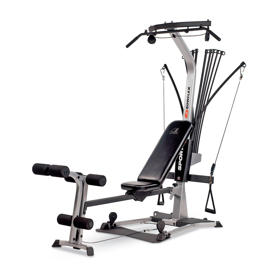
Bowflex Sport Assembly Instructions Manual
Hide thumbs
Also See for Bowflex Sport:
- Assembly instructions manual (24 pages) ,
- Owner's manual (78 pages) ,
- Assembly instructions manual (21 pages)

Related Manuals for Bowflex Bowflex Sport


Summary of Contents for Bowflex Bowflex Sport
- Page 1 Assembly Instructions Power I_ 17392 RevAA (03/2004)
-
Page 2: Before You Assemble
The Bowflex" Sport home gym's exceptional resistance and quality is umnatched by any other single piece of home fitness The Bowflex' Sport_'_home gym is the best home fitness equipment available. You will not believe the amazing results product available, and .just about to prove it... - Page 3 Know Your Machine Basic Assembly Principles Here are a few basic tips that will make your assembly of the Bowflex C:_> Sport home quick easy. By using these principles, can simplify each process save yourself extra time eff'ort. 1. To make...
-
Page 4: Tools You Will Need
Tools You Will Need You will need the following tools to complete the assembly of your Bowflex _ Sport TMhome gym. If you don't have these tools, you can find them at any hardware or department store for a reasonable price. - Page 5 Assembly Guide Figure Step I - Attach the Lower Lat Tower to the Base Platform Locate the folbwing items: Channels Mounting • hem #1 - Lower Lat Tower • hem #2 - Base Platform • hem #H - (4) 3/8" X 3" Button Head Screws •...
- Page 6 Assembly Guide Step 3 - Attach the Squat Platform to the Main Assembly Locate the following items: • From Step 2 - Base Plafform/Lat Tower (Main) Assembly Item #5 - Squat Platform Item #I - (2) 3/8" X 3 1/4" Button Head Screws Item #N - (4) 3/8"...
- Page 7 Assembly Guide Step 4 - Attach the Chest Bar with Pulleys to the Figure Main Assembly Locate the following items: • From Step 3 - Main Assembly • hem #6 - Chest Bar w/Ptflleys - Do not unwrap cables! • hem #K - (2) 3/8" X 5" Button Head Screws •...
- Page 8 Assembly Guide Step 6 - Attach the Seat Rail to the Seat Assembly Figure Locate the following items: • From Step 5 - Seat Pad/Seat Bracket Assembly • hem #9 - Seat Rail Seat Bracket Seat Pad/ Assembly Undo the twist ties from the 'Rail Pivot Bushings and remove the Bushings.
-
Page 9: Leg Assembly
Assembly Guide Figure Step 8 - Attach the Rear l_eg to the Seat Rail Locate the following items: • From Step 6 - Seat Rail Assembly • From Step 7 - Rear Leg Assembly • hem#J - (1) 3/8" X 4 1/4" Button Head Screw •... - Page 10 Assembly Guide Step 9 - Attach the Seat Rail to the Main Assembly Locate the following items: • From Step 4 - Main Assembly • From Step 8 - Seat Rail Assembly • hem #12 - Seat Rail Knob • hem#J - (1) 3/8"X 4 1/4"...
- Page 11 Assembly Guide Step 10 - Attach the l_eg Extension Pivot Tube Figure Locate the following items: Bracket • Item #13 - Leg Extension Piw_t Tube • From Step 9 - Main Assembly • hem #30 - Lock Out Pin • Item #G - (1) 3/8" X 2 3/4" Button Head Screw •...
- Page 12 Assembly Guide Step 11 - Attach the Rollers to the Leg Extension Figure Locate the following items: From Step 10 - Main Assembly Item #14 - Foam Rollers Item #15 - Foam Roller End Caps hem #16 - Short Chrome Roller Tubes hem #17 - Long Chrome Roller Tube Item #18 - Roller Tube Spacers There are (3) Chrome...
- Page 13 Assembly Guide Step 13 - Assemble the Leg Extension Seat Fi uro Locate the following items: • Item #19 - Leg Extension Seat Pad Item #21 Extension Seat • - Leg Support Tube • Item #C - (4) 5/16" X 3/4" Button Head Screws •...
- Page 14 Assembly Guide Figure Step 14 - Attach the Leg Extension Seat to the Main Seat Extension Assembly Locate the following items: • From Step 13 - Leg Extension Seat Assembly • From Step 12 - Main Assembly Support Tube Bracket Hooks The Leg Extension Seat Assembly is removeable, and can be attached to the Rear Leg Assembly easily by phcing the Rail...
- Page 15 Assembly Guide Step 16 - Attach the Upper l_at Tower to the Lower Locate the following items: Tower Upper Lat ]_ • From Step 15 - Upper Lat Tower Assembly • From Step 14 - Main Assembly • hem #E - (6) 3/8" X 3/4" Button Head Screw •...
- Page 16 Assembly Guide Figure Step 18 - Attach the Rod Box Frame to the l_at Tower Locate the following items: Rod Box Frame • From Step 16 - Main Assembly • From Step 17 - Rod Box!Frame Assembly hem #K 3/8" X 5" Button Head Screws •...
- Page 17 Assembly Guide Step 20 - Attach the Faceplate Back Panels Figure Locate the following items: • Item #27 - Faceplate Right Back Panels • hem #28 - Faceplate Left Back Panels • From Step 19 - Main Assembly • Item #A - (2) #10 Phillips Head Screws Slide each F'aceplate Back Panel (items #27 &...
- Page 18 BOWFLEX ® SPORT HOME GYM. Steps 23 through 26 illustrate how to route and connect Cables to your new Bowflex ® Sport '_ Home Gym. Figure - Rod Cables Step 23 - Route the Rod Cables Locate the following items: •...
- Page 19 Snap Hook on the Chest Bar. Fasten the Snap Hook attached to the Squat Cables to the corresponding Squat Bar "D" Ring. Repeat for remaining Squat Cable. CONGRATULATIONS! You have successfiflly completed assembly of your Bowflex ® Sport '_' Home Gym!
- Page 20 1-800-663-6315 for assistance. BOWFLEX o (O 2004, The Natttikts Group, Ii_c. 1400 N.E. 136th Ave. Var_cotwer, _,VA 98684. Bowflex Sport, Nattilus, Power Rods _m and the Bowfl ex Sport al_d Nautilus logos are registered trademarks of Nautilus, I_c.