Table of Contents
Advertisement
Quick Links
SERVICE MANUAL
WINDOW/WALL TYPE
ROOM AIR CONDITIONER
Heat Controller, Inc. • 1900 Wellworth Ave. • Jackson, MI 49203 • (517)787-2100 • www.heatcontroller.com
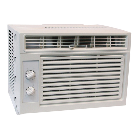
Room Air Conditioner
with R-410A:
RG-51G
-
Before using your air conditioner, please read
this manual carefully and keep it for future reference.
Advertisement
Table of Contents

Related Manuals for Heat Controller RG-51G


Summary of Contents for Heat Controller RG-51G
-
Page 1: Room Air Conditioner
ROOM AIR CONDITIONER Room Air Conditioner with R-410A: RG-51G Before using your air conditioner, please read this manual carefully and keep it for future reference. Heat Controller, Inc. • 1900 Wellworth Ave. • Jackson, MI 49203 • (517)787-2100 • www.heatcontroller.com... -
Page 2: Table Of Contents
RG-51G Service Manual Room Air Conditioner with R-410A Heat Controller, Inc. Table of Contents 1.PRECAUTIONS ......................2 1.1 Safety precautions ..................... 2 1.2 Warning ......................2 1.3 Caution ......................2 2. FEATURES AND PANEL ................... 2 2.1 Features......................2 2.2 Control panel illustration ..................3 POWER ......................... -
Page 3: Precautions
Heat Controller, Inc. Room Air Conditioner with R-410A RG-51G Service Manual 1.PRECAUTIONS 1.1 Safety precautions • To prevent injury to the user or property damage, the following instructions must be followed. • Incorrect operation due to ignoring instruction will cause harm or damage. -
Page 4: Control Panel Illustration
RG-51G Service Manual Room Air Conditioner with R-410A Heat Controller, Inc. 2.2 Control panel illustration RG-51G Series Note: The controls featured above are representative of many available models. Your model may offer slightly different features. -
Page 5: Power
Heat Controller, Inc. Room Air Conditioner with R-410A RG-51G Service Manual POWER: • Rotate the knob to any position except the OFF position to start the unit. To turn off the unit, rotate the knob to the OFF position. COOL MODE: • The desired cool setting is selected by rotating the knob to the right to the appropriate location. -
Page 6: Unit Dimensions
Room Air Conditioner with R-410A RG-51G Service Manual Heat Controller, Inc. 3. UNIT DIMENSIONS 3.1 Unit dimensions SERIES A (inch/mm) B (inch/mm) C (inch/mm) RG-51G 16 1/4” / 412 12 5/16” / 312 13 3/4” / 350... -
Page 7: Operation Limits
Heat Controller, Inc. Room Air Conditioner with R-410A RG-51G Service Manual 4. OPERATION LIMITS 4.1 Cooling operation Outdoor unit air temp DB Indoor air temp DB Note: The chart is the result from the continuous operation under constant air temperature conditions. However, excludes the initial pull-down stage. -
Page 8: Component Operation & Testing
RG-51G Service Manual Room Air Conditioner with R-410A Heat Controller, Inc. 6. COMPONENT OPERATION & TESTING WARNING: DISCONNECT ThE POWER CORD FROM ThE POWER PLUG BEFORE SERVICING OR TESTING. COMPRESSORS Compressors are single phase, 115 volt, depending on the model unit. All compressor motors are permanent split capacitor type using only a running capacitor across the start and run terminal. - Page 9 Heat Controller, Inc. Room Air Conditioner with R-410A RG-51G Service Manual C. Low temperature difference across coil. The compressor valves are faulty - replace the compressor. ThERMAL OVERLOAD (External) Some compressors are equipped with an external overload which is located in the compressor terminal box adjacent to the compressor body (see Figure 3.) The overload is wired in series...
- Page 10 RG-51G Service Manual Room Air Conditioner with R-410A Heat Controller, Inc. 1. Determine that capacitor is serviceable. 2. Disconnect fan motor wires from fan speed switch or system switch. 3. Apply “live” test cord probes on red wire and common terminal of capacitor. Motor should run at high speed.
-
Page 11: Sealed Refrigeration System Repairs
Heat Controller, Inc. Room Air Conditioner with R-410A RG-51G Service Manual SEALED REFRIGERATION SYSTEM REPAIRS EQUIPMENT REQUIRED: 1. Voltmeter 2. Ammeter 3. Ohmmeter 4. E.P.A. Approved Refrigerant Recovery System. 5. Vacuum Pump (capable of 200 microns or less vacuum.) 6. Acetylene Welder 7. - Page 12 RG-51G Service Manual Room Air Conditioner with R-410A Heat Controller, Inc. The following procedure applies when replacing components in the sealed refrigeration circuit or repairing refrigerant leaks. (Compressor, condenser, evaporator, capillary tube, refrigerant leaks, etc.) 1. Recover the refrigerant from the system at the line located on the high side of the system by installing a line tap on the line.
-
Page 13: Wiring Diagram
Then start compressor and enter the balance of the charge, gas only, into the low side. The introduction of liquid into the low side, without the use of a capillary tube, will cause damage to the discharge valve of the rotary compressor. 7. WIRING DIAGRAM Wiring Diagram For Mechanical RG-51G:... -
Page 14: Troubleshooting
RG-51G Service Manual Room Air Conditioner with R-410A Heat Controller, Inc. 8. TROUBLEShOOTING In general, possible trouble is classified by three types of failures. One is called Starting Failure which is caused from an electrical defect, another is ineffective Air Conditioning caused by a defect in the refrigeration circuit and improper application, and the other is called the Structure Damage. - Page 15 Heat Controller, Inc. Room Air Conditioner with R-410A RG-51G Service Manual The fan motor doesn’t work. Check the power supply. Check whether the indoor (outdoor) fan is locked. Check the wiring. Check whether the relays on PCB for motor work normally.
- Page 16 RG-51G Service Manual Room Air Conditioner with R-410A Heat Controller, Inc. Water drips from the unit. Check whether the ambient humidity is too high. Check whether the indoor outlet airflow foam is too wet, and louver drip. Check if the indoor airflow foam is too wet and if water is dripping from the louver.
-
Page 17: General Troubleshooting
Heat Controller, Inc. Room Air Conditioner with R-410A RG-51G Service Manual 8.2 General Troubleshooting PROBLEM POSSIBLE CAUSE REMARK No power Check voltage at electrical outlet. Correct if none. Check voltage at the power cord terminal. Replace the Power supply cord power cord if none. - Page 18 RG-51G Service Manual Room Air Conditioner with R-410A Heat Controller, Inc. PROBLEM POSSIBLE CAUSE REMARK Air filter Clean or replace if restricted. Vent door Close if open. Determine if the unit is properly sized for the area Unit undersized to be cooled or heated.
- Page 19 Heat Controller, Inc. Room Air Conditioner with R-410A RG-51G Service Manual PROBLEM POSSIBLE CAUSE REMARK Check the voltage. Call an electrician No power if no within the limit. Check the terminals. Repair and Wiring correct if loose. No cooling Check and adjust the thermostat.
- Page 20 03/2010 04/2009...