
Related Manuals for Windsor CV34


Summary of Contents for Windsor CV34
- Page 1 34™ Operating instructions (ENG) MODELS: CV34 10125650 CV34X 10125790 Read these instructions before using the machine. 86347810-T 02/09/12...
-
Page 2: Machine Data/Overview
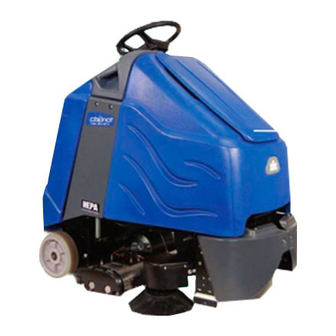
Chariot® iVacuum 34™ brushes and vacuums debris from the floor and stores it in the debris tray and vacuum bags. Warranty Registration Thank you for purchasing a Windsor product. Warranty registration is quick and easy. Your registration will allow us to serve you better over the lifetime of the product. To register your product go to : www.windsorind.com/WarrantyRegistration.aspx... -
Page 3: Table Of Contents
Table of Contents Parts Machine Data/Overview ..... . 2 Brush Deck - Debris Tray ....38 Table of Contents . -
Page 4: How To Use This Manual
Drive Motor & Brake The PARTS LIST section contains assembled parts illustrations and corresponding parts list. The parts lists Parts may be ordered from authorized Windsor include a number of columns of information: dealers. When placing an order for parts, the machine REF - column refers to the reference number on the model and machine serial number are important. -
Page 5: Safety
Safety IMPORTANT SAFETY INSTRUCTIONS When using an electrical appliance, basic precaution must always be followed, including the following: READ ALL INSTRUCTIONS BEFORE USING THIS MACHINE. To reduce the risk of fire, electric shock, or injury: Use only indoors. Do not use outdoors or expose to rain. Use only as described in this manual. -
Page 6: Hazard Intensity Level
WHEN SERVICING MACHINE: Avoid moving parts. Do not wear loose clothing; jackets, shirts, or sleeves when working on the machine. Use Windsor approved replacement parts. Batteries emit hydrogen gas. Explosion or fire can result. Keep sparks and open flame away. Keep solution tank in raised position when charging. -
Page 7: Safety Label Location
Safety Safety Label Location These drawings indicate the location of safety labels on the machine. If at any time the labels become illegible, promptly replace them. 86244310 PRV NO. 500956 CAUTION LABEL 86252520 PRV NO. 80885 BATTERY CAUTION 86243830 (2) PRV NO. -
Page 8: Operations
Operations Technical Specifications ITEM DIMENSION/CAPACITY Nominal Power 1548 W Rated Voltage 36 Volts DC Rated Amperage 43 amps Batteries 3 X12 Volt 195-215 AH @ 20 hr. rate Battery Compartment Dimensions 21 in. x 16 in. x 17 in. tall (533mm x 406mm x 432mm) Propelling Motor 0.75 HP (560 W) Brush Motor... - Page 9 Operations ITEM MEASURE Height 50.6 inches (1285 mm) Length 52.5 inches (1330 mm) Width without deck 26.5 inches (670 mm) Width of deck 32.0 inches (813 mm) Width with side broom 34.5 inches (876 mm) WIDTH LENGTH HEIGHT This appliance is not intended for use by persons (including children) with reduced physical, sensory or mental capabilities, or lack of experience and knowledge, unless they have been given supervision or instruction concerning use of the appliance by a person responsible for their safety.
-
Page 10: How This Machine Works
Operations How This machine Works The function of the operator control system is to control the direction and speed of the machine. The directional The Chariot® iVacuum 34™ is a battery powered, self- control system consists of the direction control switch, propelled, vacuum intended for commercial use. -
Page 11: Components
Operations Components 8. Deck Lift 9. Paper Bag 1. Bag Access Lid 10. Pedal Platform 2. Brush Deck 11. Rear Cover 3. Cloth Bag 12. Cover 4. Control Panel-Drive 13. Side Broom 5. Control Panel-Vacuum 6. Control Housing 7. Cover Lid 86347810 Chariot iVacuum 34... -
Page 12: Drive Controls
Operations Drive Controls 86347810 Chariot iVacuum 34... - Page 13 Operations 1. Key Switch 6. Drive Reset Button 2. Emergency Stop/Brake Switch 7. Horn Button 3. Directional Control Switch 8. Steering Wheel 4. Throttle Pedal 9. Battery Discharge Indicator 5. Speed Control Switch 10. Hour Meter 1. KEY SWITCH Controls the power for machine functions. To turn the machine power on, rotate key clockwise.
- Page 14 Operations 5. SPEED CONTROL SWITCH Controls the maximum speed of the machine. Speed 1 is intended for vacuuming. Speeds 2 and 3 are recom- mended for transport only, not vacuuming. To increase speed, press the top of the switch. To decrease speed, press bottom of the switch. Speeds can be adjusted at any time, whether machine is moving or not.
- Page 15 Operations 9. BATTERY DISCHARGE INDICATOR Indicates the charge level of the batteries. The meter display is divided into 10 vertical bars. Bars illuminated on the far right indicate full charge. Bars flashing near the left side indicate the batteries should be recharged. Further operation of the machine could damage the machine or the batteries.
-
Page 16: Deck Controls
Operations Brush Lift Lever Deck Controls Brush Lift Lever Raises and lowers the brush deck, side broom and turns the vacuum motor on and off. To lower brush deck and start vacuum motor and brushes, lift the lever from its raised position. To raise brush deck and stop vacuum motor and brushes, lift the lever from its lowered position. -
Page 17: Pre-Run Machine Inspection
Operations Pre-run Machine Inspection Emergency Stop Procedures Do a pre-run inspection to find possible problems that 1. Release the throttle pedal by lifting right foot. could cause poor performance or lost time from break- 2. Turn machine power off with key switch by turning down. -
Page 18: Normal Vacuuming
Operations Normal Vacuuming To Begin Vacuuming Plan the vacuuming pattern in advance. The longest track is around the perimeter of the area to be cleaned. For efficient operation, the runs should be the longest When operating the machine around people, pay possible without turning or stopping. -
Page 19: To Stop Vacuuming
Operations To Stop Vacuuming 6. Remove cloth bag lip from nozzle. 7. Remove cloth band and paper bag together from 1. Raise the brush deck, which turns off brushes and vacuum box. vacuum. 8. Remove paper bag from cloth bag and dispose of 2. -
Page 20: Maintenance
Maintenance Service Schedule BEFORE AFTER EACH MAINTENANCE EACH WORK WORK 50 HRS 100 HRS 200 HRS PERIOD PERIOD Check water level of batteries after charging; add distilled water if necessary Check that the vacuum box lid seal tightly Visually check for damaged or worn tires. Check vacuum hose connections. -
Page 21: Batteries
Maintenance Batteries 4. Batteries 5. Battery Tray 1. Rear Cover Retainer Knob 6. Battery Tray Latch 2. Rear Cover 3. Battery Connector-Machine 86347810 Chariot iVacuum 34... -
Page 22: Battery Maintenance
Maintenance Batteries (Wet Cell Only) The batteries provide the power to operate the When servicing machine, avoid contact with machine. The batteries require regular maintenance to battery acid. keep them operating at peak efficiency. The machine batteries will hold their charge for long periods of time, but they can only be charged a certain Batteries emit hydrogen gas. -
Page 23: Checking Battery Specific Gravity
Maintenance Checking Battery Specific Gravity Charging Batteries Use a hydrometer to check the battery specific gravity. When servicing machine, avoid contact with battery acid. Batteries emit hydrogen gas. Explosion or fire can result. Keep sparks and open flame away. Keep covers open when charging. -
Page 24: Changing Batteries
Maintenance 5. Replace the battery caps, and leave them in place Changing Batteries while charging. Stop the machine in a clean area next to the charger. 6. Unplug the battery connector from the machine. Turn off machine. SAFTEY: When charging, connect the charger to the SAFETY: Before leaving or servicing the machine;... -
Page 25: Brush Deck
Maintenance Brush Deck 1. Brush Deck Lift Cable 2. Brush Door 3. Brush Motor 4. Side Broom 5. Side Broom Lift Cable 86347810 Chariot iVacuum 34... -
Page 26: Brush Removal
Maintenance Brush Deck Debris Tray Removal The dual cylindrical head is designed to agitate the 1. Release the debris tray spring clip. carpet while vacuuming. The first scrubbing brush 2. Slide the debris tray away from machine. turns in a clockwise rotation when viewed from the right of operator's side of machine. -
Page 27: To Replace Brush Motor
Maintenance Brush Motor Carbon Brush Replacement 1. Scribe alignment mark on motor barrel to motor cap. Remove two bolts. Do not use a pressure washer to clean around the brush motors. Use tap pressure only. 2. Remove end cap from motor. NOTE: Motors contain two wave washers in cap. -
Page 28: Circuit Breakers
Maintenance CIRCUIT BREAKERS Circuit Breakers Circuit breakers interrupt the flow of power in the event of an electrical overload. When a circuit breaker is tripped, reset it by pressing the exposed button. If a circuit breaker continues to trip, the cause of the elec- trical overload should be found and corrected. -
Page 29: Vacuum Motor Carbon Brush Replacement
Maintenance To Remove Vacuum Motor 1. Remove rear cover. Disconnect batteries before working on machine. Only 2. Remove two screws from top of control panel and qualified personnel should work inside machine. four screws from side of control panel housing. Always wear eye protection and protective clothing when working on or near batteries. - Page 30 Maintenance Drive Motor & Brake 1. Drive motor 2. Parking brake 86347810 Chariot iVacuum 34...
-
Page 31: Electric Parking Brake Engagement
Maintenance Electric Parking Brake Engagement To disengage brake: SAFETY: Before leaving or servicing machine, stop on a level surface, turn off machine and remove key. Electric Brake Engagement This machine is equipped with an electric parking brake. The brake automatically engages and keeps the machine from moving whenever the operator steps off the platform or when emergency stop is engaged. -
Page 32: Drive Motor Carbon Brush Replacement
Maintenance Drive Motor Carbon Brush Replacement 7. Install new brush and reinstall connecting screw and lead. 8. When all new brushes are installed. Place all in retracted position, held into brush holder by spring Do not use a pressure washer to clean around the tension. -
Page 33: Pushing Machine
Maintenance Pushing Machine Preparation for Loading/Unloading Trailer The machine may be pushed for short distances at Before loading or unloading machine from trailer, brush speeds not to exceed 5 mph. Be careful to avoid head must be in the up position before loading. damaging machine. -
Page 34: Troubleshooting
Maintenance Troubleshooting PROBLEM CAUSE SOLUTION No power to machine Battery disconnected Check all battery cable connections Emergency shut-off activated Reset Faulty key switch Replace switch Little or no propel Low battery charge Charge batteries Machine turned on with pedal not in Allow pedal to return to neutral. -
Page 35: Propel Circuit Board Troubleshooting
Maintenance Propel Circuit Board Troubleshooting Curtis 1228 LED DIAGNOSTICS During normal operation, with no faults present, the status LED is steadily on. If the controller detects a fault, the status LED provides two types of information. First, it displays a slow flash (2 Hz) or a fast flash (4 Hz) to indicate the severity of the fault. Slow-flash faults are self-clearing;... - Page 36 Maintenance PROGRAMMER LCD DISPLAY EXPLANATION POSSIBLE CAUSE CODE 1. Misadjusted throttle. PROC/WIRING FAULT HPD fault present for >10 sec. 2. Broken throttle pot or throttle mechanism. 1. Electromagnetic brake driver BRAKE ON FAULT brake On fault shorted. 2. Electromagnetic brake coil open.