Table of Contents
Advertisement
Advertisement
Table of Contents

Related Manuals for Gigabyte GA-970A-DS3


Summary of Contents for Gigabyte GA-970A-DS3
- Page 1 GA-970A-DS3 User's Manual Rev. 1001 12ME-970ADS3-1001R...
-
Page 3: Identifying Motherboard Revision
GIGABYTE's prior written permission. Documentation Classifications In order to assist in the use of this product, GIGABYTE provides the following types of documentations: For quick set-up of the product, read the Quick Installation Guide included with the product. -
Page 4: Table Of Contents
Table of Contents GA-970A-DS3 Motherboard Layout ................5 GA-970A-DS3 Motherboard Block Diagram ..............6 Chapter 1 Hardware Installation ..................7 Installation Precautions ..................7 Product Specifications ..................8 Installing the CPU ..................10 Installing the Memory ..................11 Installing an Expansion Card ................. 11 Back Panel Connectors .................. -
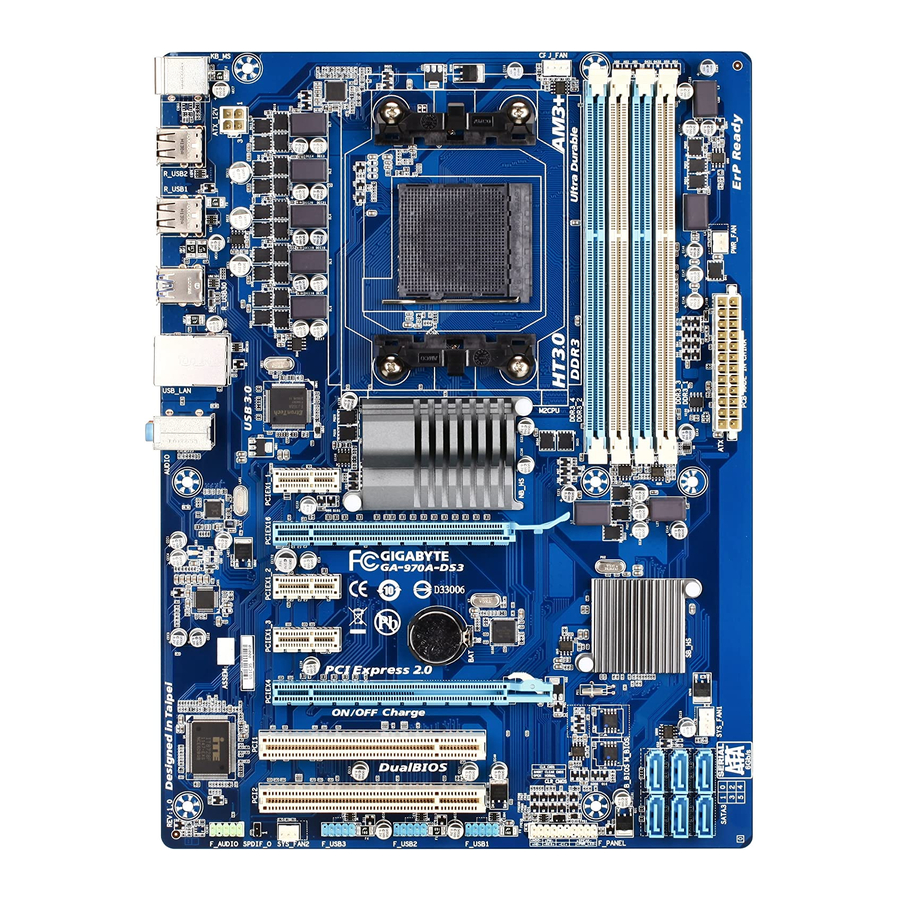
Page 5: Ga-970A-Ds3 Motherboard Layout
GA-970A-DS3 Motherboard Layout CPU_FAN KB_MS ATX_12V R_USB2 Socket AM3+ R_USB1 PWR_FAN R_USB30 USB_LAN Etron EJ168 AUDIO AMD 970 PCIEX1_1 (Note) Realtek GbE LAN PCIEX16 GA-970A-DS3 PCIEX1_2 CODEC PCIEX1_3 AMD SB950 PCIEX4 SYS_FAN1 M_BIOS PCI1 B_BIOS PCI2 SATA3 0 2 4... -
Page 6: Ga-970A-Ds3 Motherboard Block Diagram
GA-970A-DS3 Motherboard Block Diagram CPU CLK+/- (200 MHz) DDR3 2000 (O.C.)/1866/1600/ AM3+/AM3 CPU 1333/1066 MHz 1 PCI Express x16 Dual Channel Memory Hyper Transport Bus PCIe CLK (100 MHz) 2 USB 3.0/2.0 3 PCI Express x1 RJ45 Realtek Etron GbE LAN... -
Page 7: Chapter 1 Hardware Installation
Chapter 1 Hardware Installation Installation Precautions The motherboard contains numerous delicate electronic circuits and components which can become damaged as a result of electrostatic discharge (ESD). Prior to installation, carefully read the user's manual and follow these procedures: Prior to installation, make sure the chassis is suitable for the motherboard. •... -
Page 8: Product Specifications
Support for DDR3 2000(O.C.)/1866/1600/1333/1066 MHz memory modules Š * To support a DDR3 1866 MHz (and above) memory, you must install an AM3+ CPU first. (Go to GIGABYTE's website for the latest supported memory speeds and memory modules.) Audio Realtek HD audio codec Š... - Page 9 Operating Support for Microsoft Windows 7/Vista/XP Š ® System Form Factor ATX Form Factor; 30.5cm x 22.5cm Š * GIGABYTE reserves the right to make any changes to the product specifications and product-related information without prior notice. - 9 -...
-
Page 10: Installing The Cpu
Read the following guidelines before you begin to install the CPU: Make sure that the motherboard supports the CPU. • (Go to GIGABYTE's website for the latest CPU support list.) Always turn off the computer and unplug the power cord from the power outlet before installing the •... -
Page 11: Installing The Memory
Make sure that the motherboard supports the memory. It is recommended that memory of the same • capacity, brand, speed, and chips be used. (Go to GIGABYTE's website for the latest supported memory speeds and memory modules.) Always turn off the computer and unplug the power cord from the power outlet before installing the •... -
Page 12: Back Panel Connectors
Back Panel Connectors PS/2 Keyboard/Mouse Port Use this port to connect a PS/2 mouse or keyboard. USB 2.0/1.1 Port The USB port supports the USB 2.0/1.1 specification. Use this port for USB devices such as a USB keyboard/mouse, USB printer, USB flash drive and etc. USB 3.0/2.0 Port The USB 3.0 port supports the USB 3.0 specification and is compatible to the USB 2.0/1.1 specification. -
Page 13: Internal Connectors
Internal Connectors ATX_12V SATA3 0/1/2/3/4/5 CPU_FAN F_PANEL SYS_FAN1/SYS_FAN2 F_AUDIO PWR_FAN SPDIF_O CLR_CMOS F_USB1/F_USB2/F_USB3 Read the following guidelines before connecting external devices: First make sure your devices are compliant with the connectors you wish to connect. • Before installing the devices, be sure to turn off the devices and your computer. Unplug the power •... - Page 14 1/2) ATX_12V/ATX (2x2 12V Power Connector and 2x12 Main Power Connector) With the use of the power connector, the power supply can supply enough stable power to all the components on the motherboard. Before connecting the power connector, first make sure the power supply is turned off and all devices are properly installed.
- Page 15 3/4/5) CPU_FAN/SYS_FAN1/SYS_FAN2/PWR_FAN (Fan Headers) The motherboard has a 4-pin CPU fan header (CPU_FAN), a 3-pin (SYS_FAN2) and a 4-pin (SYS_FAN1) system fan headers, and a 3-pin power fan header (PWR_FAN). Most fan headers possess a foolproof insertion design. When connecting a fan cable, be sure to connect it in the correct orientation (the black connector wire is the ground wire).
- Page 16 7) SATA3 0/1/2/3/4/5 (SATA 6Gb/s Connectors) The SATA connectors conform to SATA 6Gb/s standard and are compatible with SATA 3Gb/s and SATA 1.5Gb/s standard. Each SATA connector supports a single SATA device. The AMD SB950 South Bridge supports RAID 0, RAID 1, RAID 5, RAID 10, and JBOD. Refer to Chapter 4, "Configuring SATA Hard Drive(s),"...
-
Page 17: Front Panel Header
9) F_PANEL (Front Panel Header) Connect the power switch, reset switch, speaker, chassis intrusion switch/sensor and system status indicator on the chassis to this header according to the pin assignments below. Note the positive and negative pins before connecting the cables. Message/Power/ Power Speaker... - Page 18 10) F_AUDIO (Front Panel Audio Header) The front panel audio header supports Intel High Definition audio (HD) and AC'97 audio. You may connect your chassis front panel audio module to this header. Make sure the wire assignments of the module connector match the pin assignments of the motherboard header.
- Page 19 12) F_USB1/F_USB2/F_USB3 (USB Headers) The headers conform to USB 2.0/1.1 specification. Each USB header can provide two USB ports via an optional USB bracket. For purchasing the optional USB bracket, please contact the local dealer. Pin No. Definition Power (5V) Power (5V) USB DX- USB DY-...
-
Page 20: Chapter 2 Bios Setup
To see more advanced BIOS Setup menu options, you can press <Ctrl> + <F1> in the main menu of the BIOS Setup program. To upgrade the BIOS, use either the GIGABYTE Q-Flash or @BIOS utility. • Q-Flash allows the user to quickly and easily upgrade or back up BIOS without entering the operating system. -
Page 21: The Main Menu
The Main Menu Once you enter the BIOS Setup program, the Main Menu (as shown below) appears on the screen. Use arrow keys to move among the items and press <Enter> to accept or enter a sub-menu. (Sample BIOS Version: F1a) CMOS Setup Utility-Copyright (C) 1984-2011 Award Software MB Intelligent Tweaker(M.I.T.) Load Fail-Safe Defaults... -
Page 22: Mb Intelligent Tweaker(M.i.t.)
MB Intelligent Tweaker(M.I.T.) CMOS Setup Utility-Copyright (C) 1984-2011 Award Software MB Intelligent Tweaker(M.I.T.) Item Help CPU Clock Ratio [Auto] Menu Level CPU NorthBridge Freq. [Auto] Core Performance Boost (Note) [Enabled] CPB Ratio [Auto] (Note) Turbo CPB [Disabled] (Note) CPU Host Clock Control [Auto] x CPU Frequency(MHz) PCIE Clock(MHz) - Page 23 CPU Frequency(MHz) & Allows you to manually set the CPU host frequency. The adjustable range is from 200 MHz to 500 MHz. This option is configurable only when CPU Host Clock Control is set to Manual. Important It is highly recommended that the CPU frequency be set in accordance with the CPU specifications.
- Page 24 CMOS Setup Utility-Copyright (C) 1984-2011 Award Software DRAM Configuration Item Help ProcOdt(ohms) [Auto] [Auto] Menu Level DQS Drive Strength [Auto] 1.0x [Auto] 1.0x Data Drive Strength [Auto] 1.0x [Auto] 1.0x MEMCLK Drive Strength [Auto] 1.25x [Auto] 1.25x Addr/Cmd Drive Strength [Auto] 1.5x [Auto]...
- Page 25 Write Recovery Time & Options are: Auto (default), 5T~8T, 10T, 12T, 14T, 16T. Precharge Time & Options are: Auto (default), 4T~10T. Row Cycle Time & Options are: Auto (default), 10T~56T. RAS to RAS Delay & Options are: Auto (default), 1T~9T. ** DCTs Drive Strength ** ProcOdt(ohms) &...
- Page 26 Bank Interleaving & Enables or disables memory bank interleaving. Enabled allows the system to simultaneously access different banks of the memory to increase memory performance and stability. (Default: Enabled) DQS Training Control & Enables or disables memory DQS training each time the system restarts. (Default: Skip DQS) CKE Power Down Mode &...
-
Page 27: Standard Cmos Features
Standard CMOS Features CMOS Setup Utility-Copyright (C) 1984-2011 Award Software Standard CMOS Features Item Help Date (mm:dd:yy) Wed, Jan 4 2012 Menu Level Time (hh:mm:ss) 22:31:24 IDE Channel 0 Master [None] IDE Channel 0 Slave [None] IDE Channel 1 Master [None] ... -
Page 28: Advanced Bios Features
Advanced BIOS Features CMOS Setup Utility-Copyright (C) 1984-2011 Award Software Advanced BIOS Features Item Help Load Line Control [Auto] Menu Level AMD C1E Support [Auto] Virtualization [Disabled] AMD K8 Cool&Quiet control [Auto] CPU Unlock [Disabled] (Note) CPU core Control [Auto] (Note) x CPU core 0... - Page 29 (Default: Disabled) Full Screen LOGO Show & Allows you to determine whether to display the GIGABYTE Logo at system startup. Disabled displays normal POST message. (Default: Enabled) IOMMU support &...
-
Page 30: Integrated Peripherals
Integrated Peripherals CMOS Setup Utility-Copyright (C) 1984-2011 Award Software Integrated Peripherals Item Help OnChip SATA Controller [Enabled] Menu Level OnChip SATA Type [Native IDE] x OnChip SATA Port4/5 Type x OnChip SATA RAID5 Support Enabled OnChip SATA3.0 Support [Enabled] x OnChip SATA Port as ESP Press Enter Onboard LAN Function... - Page 31 Port0 as ESP/Port1 as ESP/Port2 as ESP/Port3 as ESP & This option is configurable only when OnChip SATA Type is set to AHCI. Enabled will speed up the hot plug detection of the connected SATA device. (Default: Disabled) Port4 as ESP/Port5 as ESP &...
-
Page 32: Power Management Setup
Power Management Setup CMOS Setup Utility-Copyright (C) 1984-2011 Award Software Power Management Setup Item Help ACPI Suspend Type [S3(STR)] Menu Level Soft-Off by Power button [Instant-off] USB Wake Up from S3 [Enabled] Modem Ring Resume [Disabled] PME Event Wake Up [Enabled] HPET Support [Enabled]... - Page 33 Power On By Mouse & Allows the system to be turned on by a PS/2 mouse wake-up event. Note: To use this function, you need an ATX power supply providing at least 1A on the +5VSB lead. Disabled Disables this function. (Default) Double Click Double click on left button on the PS/2 mouse to turn on the system.
-
Page 34: Pc Health Status
PC Health Status CMOS Setup Utility-Copyright (C) 1984-2011 Award Software PC Health Status Item Help Hardware Thermal Control [Enabled] Menu Level Reset Case Open Status [Disabled] Case Opened Vcore 1.424V DDR15V 1.472V +12V 11.985V +3.3V 3.280V Current System Temperature Current CPU Temperature Current CPU FAN Speed 2360 RPM... -
Page 35: Load Fail-Safe Defaults
CPU Smart FAN Control & Enables or disables the CPU fan speed control function. Enabled allows the CPU fan to run at different speed according to the CPU temperature. You can adjust the fan speed with EasyTune based on system requirements. -
Page 36: Set Supervisor/User Password
2-11 Set Supervisor/User Password CMOS Setup Utility-Copyright (C) 1984-2011 Award Software MB Intelligent Tweaker(M.I.T.) Load Fail-Safe Defaults Standard CMOS Features Load Optimized Defaults Advanced BIOS Features Set Supervisor Password Integrated Peripherals Set User Password Power Management Setup Save &... -
Page 37: Exit Without Saving
2-13 Exit Without Saving CMOS Setup Utility-Copyright (C) 1984-2011 Award Software MB Intelligent Tweaker(M.I.T.) Load Fail-Safe Defaults Standard CMOS Features Load Optimized Defaults Quit Without Saving (Y/N)? N Advanced BIOS Features Set Supervisor Password Integrated Peripherals Set User Password ... -
Page 38: Chapter 4 Appendix
Chapter 4 Appendix Configuring SATA Hard Drive(s) Before you begin Please prepare: At least two SATA hard drives (to ensure optimal performance, it is recommended that you use two hard • drives with identical model and capacity). If you do not want to create RAID, you may prepare only one hard drive. -
Page 39: Making A Sata Raid Driver Diskette
Press <Ctrl>+<Y> keys to save the information. The message in Figure 1 will appear. Press <Ctrl>+<Y> to input the array name. If you do not input the array name, the default array name will be used. Please press Ctrl-Y key to input the LD Name or press any key to exit. -
Page 40: Regulatory Statements
"end of life" product. Restriction of Hazardous Substances (RoHS) Directive Statement GIGABYTE products have not intended to add and safe from hazardous substances (Cd, Pb, Hg, Cr+6, PBDE and PBB). The parts and components have been carefully selected to meet RoHS requirement. Moreover, we at GIGABYTE are continuing our efforts to develop products that do not use internationally banned toxic chemicals. - Page 41 - 41 -...
- Page 42 - 42 -...
- Page 43 - 43 -...
- Page 44 Tech. and Non-Tech. Support (Sales/Marketing) : http://ggts.gigabyte.com.tw WEB address (English): http://www.gigabyte.com WEB address (Chinese): http://www.gigabyte.tw You may go to the GIGABYTE website, select your language in the language list on the top right corner of the website. GIGABYTE Global Service System •...