
Related Manuals for UNI-T UT50D


Summary of Contents for UNI-T UT50D
-
Page 1: Table Of Contents
Model UT50D: OPERATING MANUAL Table of Contents Overview Unpacking Inspection Safety Information Rules For Safe Operation International Electrical Symbols The Meter Structure Functional Buttons Display Symbols Measurement Operation DC Voltage Measurement AC Voltage Measurement DC Current Measurement AC Current Measurement... - Page 2 Model UT50D: OPERATING MANUAL Maintenance General Service Replacing the Battery Replacing the Fuses...
-
Page 3: Overview
To avoid electric shock or personal injury, read the “Safety Information” and “Rules for Safety Operation” carefully before using the Meter. Digital Multimeters Model UT50D (hereafter referred to as “the Meter”) is a 3 1/2 digits with steady operations, fashionable structure and highly reliable hand-held measuring instrument. -
Page 4: Unpacking Inspection
Model UT50D: OPERATING MANUAL Item Description English Operating Manual 1 piece Test Lead 1 pair Test Clip 1 piece 1 piece Point Contact Temperature Probe 9V Battery (NEDA 1604, 6F22 or 009P) 1 piece (installed inside the Meter) In the event you find any missing or damage, please... -
Page 5: Safety Information
Model UT50D: OPERATING MANUAL Safety Information This Meter complies with the standards IEC61010: in pollution degree 2, overvoltage category (CAT. II 1000V, CAT. III 600V) and double insulation. CAT. II: Local level, appliance, PORTABLE EQUIPMENT etc., with smaller transient voltage overvoltages than CAT. -
Page 6: Rules For Safe Operation
Model UT50D: OPERATING MANUAL Rules For Safe Operation (1) Warning To avoid possible electric shock or personal injury, and to avoid possible damage to the Meter or to the equipment under test, adhere to the following rules: Before using the Meter inspect the case. Do not use the Meter if it is damaged or the case (or part of the case) is removed. - Page 7 Model UT50D: OPERATING MANUAL Rules For Safe Operation (2) Disconnect circuit power and discharge all high -voltage capacitors before testing resistance, continuity, diodes, capacitance or current. Before measuring current, check the Meter’s fuses and turn off power to the circuit before connecting the Meter to the circuit.
-
Page 8: International Electrical Symbols
Model UT50D: OPERATING MANUAL International Electrical Symbols AC (Alternating Current). DC (Direct Current). Grounding. Double Insulated. Deficiency of Built-In Battery. Warning. Refer to the Operating Manual. Diode. AC or DC. Fuse. Continuity Test. Conforms to Standards of European Union. -
Page 9: The Meter Structure
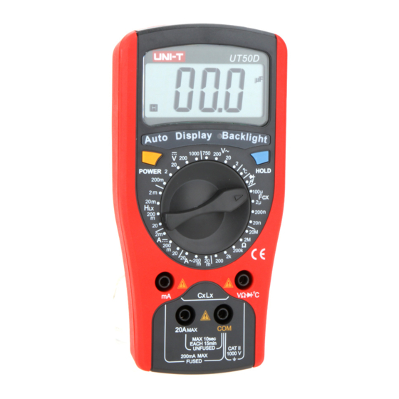
Model UT50D: OPERATING MANUAL The Meter Structure (see figure 1) (figure 1) 1. LCD Display 2. Data Hold Button. 3. Rotary Switch 4. Other Input Terminals 5. COM Input Terminal 6. 20A Input Terminal 7. mA Input terminal 8. Power... -
Page 10: Functional Buttons
Model UT50D: OPERATING MANUAL Functional Buttons Below table indicated for information about the functional button operations Button Operation Performed Turn the Meter on and off. POWER l Press down the POWER to turn (Yellow Button) on the Meter. l Press up the POWER to turn off the Meter. -
Page 11: Display Symbols
Model UT50D: OPERATING MANUAL Display Symbols(1) (see figure 2) (figure 2) Symbol Meaning Dangerous Voltages. The battery is low. Warning: To avoid false readings, which could lead to possible electric shock or personal injury, replace the battery as soon as the battery indicator appears. - Page 12 Model UT50D: OPERATING MANUAL Display Symbols(2) (see figure 2) Symbol Meaning H: Henry. The unit of Inductance. mH,H mH: Millihenry. 1 x 10 or 0.001 henry.
-
Page 13: Measurement Operation
Model UT50D: OPERATING MANUAL Make sure the Sleep Mode is not on if you found there is no display on the LCD after turning on the Meter. Make sure the Low Battery Display is not on, otherwise false readings may be provided. - Page 14 Model UT50D: OPERATING MANUAL 1. Insert the red test lead into thei V nput terminal and the black test lead into the COM input terminal. 2. Set the rotary switch to an appropriate measurement position in V range. 3. Connect the test leads across with the object being measured.
-
Page 15: Ac Voltage Measurement
Model UT50D: OPERATING MANUAL The AC voltage measurement has 4 measurement positions on the rotary switch: 2V, 20V, 200V and 750V To measure AC Voltage, connect the Meter as follows: 1. Insert the red test lead into the V terminal and the black test lead into the COM terminal. -
Page 16: Dc Current Measurement
Model UT50D: OPERATING MANUAL ( figure 4) The DC current measurement has 3 measurement positions on the rotary switch: 2mA, 200mA and 20A. To measure current, do the following: 1. Turn off power to the circuit. Discharge all high- voltage capacitors. -
Page 17: Ac Current Measurement
Model UT50D: OPERATING MANUAL Measurement Operation(5) 4. Break the current path to be tested. Connect the red test lead to the more positive side of the break and the black test lead to the more negative side of the break. - Page 18 Model UT50D: OPERATING MANUAL Measurement Operation(6) The AC current measurement has 3 measurement positions on the rotary switch: 20mA, 200mA and 20A. To measure current, do the following: 1. Turn off power to the circuit. Discharge all high-voltage capacitors. Insert the red test lead into the mA or 20A terminal and the black test lead into the COM terminal.
-
Page 19: Measuring Resistance
Model UT50D: OPERATING MANUAL Measurement Operation(7) ( figure 5) The resistance ranges are:200 ,2k ,200k ,2M ,and To measure resistance, connect the Meter as follows: 1. Insert the red test lead into the V terminal and the black test lead into the COM terminal. -
Page 20: Inductance Measurement
Model UT50D: OPERATING MANUAL Measurement Operation(8) Precision readings of resistance = Measurement displayed reading minus the short circuit value of red and black test lead. l For high resistance (>1M ), it is normal taking several seconds to obtain a stable reading. -
Page 21: Capacitance Measurement
Model UT50D: OPERATING MANUAL Measurement Operation(9) According to the size of the tested object’s leads, insert multi-purpose socket or test clip into the mA and V terminal. Set the rotary switch to an appropriate measurement position in HLx range. Insert the tested object into the corresponding jack of the multi-purpose socket or connect the test clip to the object being measured. - Page 22 Model UT50D: OPERATING MANUAL Measurement Operation(10) l For testing the capacitor with polarity, connect the red test lead or test clip to anode & black test lead or test clip to cathode l When the tested capacitor is shorted or the capacitor value is overloaded, the LCD display “1”.
-
Page 23: Temperature Measurement
Model UT50D: OPERATING MANUAL Measurement Operation(11) ( figure 8) The temperature measurement range is from -40 C ~1000 To measure temperature, connect the Meter as follows: 1. Insert the red temperature into the terminal and the black temperature probe into the COM terminal. -
Page 24: Measuring Diodes & Continuity
Model UT50D: OPERATING MANUAL Measurement Operation(12) l When temperature measeuremnet has been completed, disconnect the connection between the testing leads and te circuit under test. ( figure 9) Testing Diodes Use the diode test to check diodes, transistors, and other semiconductor devices. - Page 25 Model UT50D: OPERATING MANUAL Measurement Operation(13) 2. Set the rotary switch to 3. For forward voltage drop readings on any semiconductor component, place the red test lead on the component’s anode and place the black test lead on the component’s cathode.
- Page 26 Model UT50D: OPERATING MANUAL Measurement Operation(14) l The LCD display “1” indicating the circuit being tested is open. l When continuity testing has been completed, disconnect the connection between the testing leads and the circuit under test.
-
Page 27: Sleep Mode
Model UT50D: OPERATING MANUAL Sleep Mode To preserve battery life, the Meter automatically turns off if you do not turn the rotary switch or press any button for around 8 minutes. At that time, the Meter consumes around 10µA current. -
Page 28: General Specifications
Model UT50D: OPERATING MANUAL Maximum voltage between any Terminals and Grounding :1000V rms. Fused Protection for mA Input Terminal :0.5A, 250V fast type, 5x20mm. Fused Protection for 20A Input Terminal :Un-fused. Range :Manual ranging. Maximum Display :1999. Mesaurement Speed :Updates 2~3 times/second. -
Page 29: Accuracy Specifications
Model UT50D: OPERATING MANUAL guarantee for 1 year. Accuracy: (a% reading + b digits) Operating temperature:23 Relative humidity:<75%. Temperature coefficient: 0.1 x (specified accuracy) / 1 A. DC Voltage Accuracy Overload Protection Range Resolution 200mV 0.1mV 250V DC or AC rms. -
Page 30: Dc Current
Model UT50D: OPERATING MANUAL C. DC Current Range Resolution Accuracy Overload Protection (0.8%+1) 0.5A. 250V fast type 0.001mA fuse, 5x20mm (1.5%+1) 200mA 0.1mA 10mA (2%+5) Un-Fused Remarks: l At 20A Range: For continuous measurement 10 seconds and interval not less than 15 minutes. -
Page 31: Resistance Test
Model UT50D: OPERATING MANUAL E. Resistance Test Overload Accuracy Range Resolution Protection (0.8%+3) (0.8%+1) 250V rms (1%+5) Remarks: l At 200 range, short circuit the test lead first to display the test lead resistance value. During measurement, subtract the test lead resistance value from the displayed reading to obtain the accurate reading. -
Page 32: Temperature
Model UT50D: OPERATING MANUAL H. Temperature Overload Range Accuracy Resolution Protection (3%+3) 250V rms (1%+3) C~400 C~1000 2.5% I. Diodes and Continuity Test Diodes Open circuit voltage approx. 2.8V 250V DC or AC Continuity <70 buzzer beeps Test continuously... -
Page 33: Maintenance
Model UT50D: OPERATING MANUAL This section provides basic maintenance information including battery and fuse replacement instruction. Warning Do not attempt to repair or service your Meter unless you are qualified to do so and have the relevant calibration, performance test, and service information. - Page 34 Model UT50D: OPERATING MANUAL Warning To avoid false readings, which could lead to possible electric shock or personal injury, replace the battery as soon as the battery indicator appears. To replace battery: 1. Disconnect the connection between the testing leads and the circuit under test, and remove the testing leads away from the input terminals of the Meter.
- Page 35 Model UT50D: OPERATING MANUAL To replace the Meter’s fuse: 1. Disconnect the connection between the testing leads and the circuit under test, and remove the testing leads away from the input terminals of the Meter. 2. Turn the Meter off.
- Page 36 Model UT50D: OPERATING MANUAL Copyright 2003 Uni-Trend Group Limited. All rights reserved. Manufacturer: Uni-Trend Technology (Dongguan) Limited Dong Fang Da Dao Bei Shan Dong Fang Industrial Development District Hu Men Town, Dongguan City Guang Dong Province China Postal Code: 523 925...