Table of Contents
Advertisement
Quick Links
Advertisement
Table of Contents

Related Manuals for Planet IFT-802


Summary of Contents for Planet IFT-802
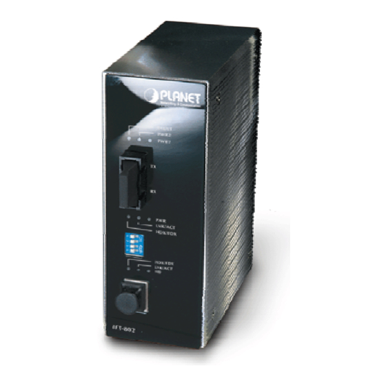
- Page 1 Industrial 10/100Base-TX to 100Base-FX Media Converter IFT-802 User's Manual...
-
Page 2: Fcc Warning
Trademarks Copyright © PLANET Technology Corp. 2006. Contents subject to which revision without prior notice. PLANET is a registered trademark of PLANET Technology Corp. All other trademarks belong to their respective owners. Disclaimer PLANET Technology does not warrant that the hardware will work properly in all environments and applications, and makes no warranty and representation, either implied or expressed, with respect to the quality, performance, merchantability, or fitness for a particular purpose. -
Page 3: Table Of Contents
Table of Contents 1. INTRODUCTION ........................4 1.1 Packet Contents ......................4 1.2 How to Use This Manual ....................4 1.3 Product Feature....................... 4 1.4 Product Specification....................... 5 2. INSTALLATION........................7 2.1 Product Description ......................7 2.2 Mounting Installation ......................11 3. -
Page 4: Introduction
1. INTRODUCTION 1.1 Packet Contents Check the contents of your package for following parts: ▫ Industrial Media Converter x1 ▫ DIN-Rail kit (screwed on the switch) ▫ Wall-mount kit (wall-mount plate with 6 screws) ▫ CD-ROM user's manual x1 If any of these are missing or damaged, please contact your dealer immediately, if possible, retain the carton including the original packing material, and use them against to repack the product in case there is a need to return it to us for repair. -
Page 5: Product Specification
EN6100-4-5 and CE EN6100-4-6 ▫ Stability testing with IEC60068-2-32(Free fall), IEC60068-2-27(Shock) and IEC60068-2-6(Vibration) 1.4 Product Specification Model IFT-802 Standard IEEE 802.3 10BASE-T IEEE 802.3u 100BASE-TX / 100BASE-FX IEEE 802.3x Flow Control and Back pressure 10/100Mbps TP CAT-3/5 (10/100Mbps) Twisted Pair cable Auto MDI/MDI-X and Auto-Negotiation... - Page 6 TX: 10/100(Green) Link (Green) Half/Full Duplex (Orange) Power Supply 12~48 VDC, Redundant power with polarity reverse and overlap current protection function Power Consumption 4.6 Watts Installation Provide DIN rail kit and wall mount plate for 3-way installation Operating environment 0~60 Degree C, 5%~90%RH (Non-condensing) Storage environment -40~85 Degree C, 5%~90%RH (Non-condensing) Dimension (W x D x H)
-
Page 7: Installation
DC power sources. If one power input fails, the other one acts as a backup. The PLANET IFT-802 also provides relay alarm outputs to warn when the port link failure, so the technician can respond quickly with appropriate emergency operation procedures. Also, there are DIP- switches to set the operation mode for relay alarm, Fiber ports, link loss forwarding function, and UTP operation mode. - Page 8 The following table provides description of the LED status and their meanings for the industrial media converter. Status Meaning Green When the IFT-802 has power input s the LED will light on Power No any power inputs Green Power on...
- Page 9 The bottom panel of the Converter consist one terminal block connector within two DC power inputs and one DC IN power jack for extra AC/DC power adapter. Figure 2-2 shows the bottom panel of the switch. Figure 2-2 IFT-802 Bottom Panel.
-
Page 10: Wiring The Power Inputs
2.1.6 Wiring the Power Inputs Please follow below steps to insert the power wire. 1. Insert the positive and negative wires into the V+ and V- connector on the terminal block connector. 2. To tighten the wire-clamp screws for preventing the DC wires to loose. 2.1.7 Wiring the Fault Alarm Contact The fault alarm contact is in the middle of terminal block connector as below figure shows. -
Page 11: Mounting Installation
Fault Alarm Contact The open circuit will form when the power failure or port link failure. 24V DC Buzzer 24V Battery The fault alarm device will send a warning signal t warn the user, ex: alarm sound or flash light. 2.2 Mounting Installation This section describes how to install the Converter and make connections to it. - Page 12 Step1: Insert the top of DIN-Rail into the track. Step2: Lightly push the button of DIN-Rail into the track. Step3: Check the DIN-Rail is tightly on the track. Step4: To remove the Converter from the track, reverse steps above. 2.2.2 Wall Mount Plate Mounting To install the converter to the wall, please follows the instructions described below.
- Page 13 Step3: Use the screws to screw the wall mount plate on the Converter. Step4: Use the hook holes at the corners of the wall mount plate to hang the Converter on the wall. Step5: To remove the wall mount plate, reverse steps above.
-
Page 14: Hardware Installation
3. Hardware Installation In this section, we will describe how to install the 10/100BaseTX to 100BaseFX Media Converter and the installation points for the attention. In Figure G, it is an example application for the Converter. Installation Steps Step1: Unpacked the Industrial media converter. Step2: Check the DIN-Rail is screwed on the Industrial media converter. - Page 15 Notice: The Fiber port has single-mode and multi-mode. To check your Industrial media converter fiber connector type, look for the sticker on the Industrial media converter. The multi-mode connector type must use 50 or 62.5/125 µm multi-mode fiber cable. The connect distance between two devices is up to 2Km.
-
Page 16: Troubleshooting
4. TROUBLESHOOTING This section is intended to help you solve the most common problems on the Industrial Media Converter. 4.1 Incorrect connections The switch port can auto detect straight or crossover cable when you link switch with other Ethernet device. For the RJ-45 connector should use correct UTP or STP cable, 10/100Mbps port use 2-pairs twisted cable. - Page 17 power connections, power losses or surges at power outlet. IF you still cannot resolve the problem, contact your local dealer for assistance. 4.2.1 Cabling RJ-45 ports: use unshielded twisted-pair (UTP) or shield twisted-pair (STP) cable for RJ-45 connections: 100Ω Category 3, 4 or 5 Cable for 10Mbps connections or 100Ω Category 5 cable for 100Mbps connections.
-
Page 18: Appendix A Networking Connection
Appendix A Networking Connection A.1 Switch‘s RJ-45 Pin Assignments Contact MDI-X 1 (TX +) 2 (TX -) 3 (RX +) 6 (RX -) 4, 5, 7, 8 Not used Not used A.2 RJ-45 cable pin assignment There are 8 wires on a standard UTP/STP cable and each wire is color-coded. The following shows the pin allocation and color of straight cable and crossover cable connection: Figure A-1: Straight-Through and Crossover Cable Please make sure your connected cables are with same pin assignment and color as above picture...